Week 4 Challenge : CFD Meshing for BMW car
AIM
- To remove the geometrical errors and perform a Topology cleanup in the BMW Car geometry.
- To create and assign PIDs and perform Surface Mesh as per assigned target lengths for PIDs and element Quality Criteria
- Construct a surface for Wind Tunnel and surface mesh the wind tunnel.
Note - There have to be Zero Off elements and only 2D Tria elements.
THEORY
The BMW car in the given problem has meshed for Aerodynamic flow analysis. For the Aerodynamic flow, a Control Volume is made in the form of a Wind Tunnel for simulating the flow of air. However, due to expensive computation, volume meshing of the Wind Tunnel is not done and a surface mesh is adopted as a mere representation of the former. Following are the systemic steps adopted to Surface mesh the whole geometry,
1. Dividing the geometry into half
Cutting the geometry of the car into half is one of the first steps. This is primarily done to reduce the effort of geometry cleaning since the Car is a symmetric structure.
2. Geometry and Topo Cleaning
The geometry and topo cleaning includes all kinds of removal of geometric and intersection errors in various parts of the car chassis. In addition to that, it also includes the geometry cleaning of tires. The geometric errors are removed with simultaneous creation and deletion of surfaces.
3. Surface Meshing of Car
The car's surface is being meshed for Aerodynamic testing. Each part of the car is meshed with a defined Target length. This is done in accordance with the values given in the problem. To perform the surface meshing at different parts of the car, the parts to be meshed are frozen to avoid the occurrence of unmeshed surfaces due to a common perimeter with different target lengths.
4. Creation and Meshing of Wind Tunnel
After the surface meshing of the car, a cuboidal surface is made to simulate the wind tunnel. Further, the wind tunnel is surface meshed.
Mesh parameters
Setting mesh parameters include setting up mesh element length and also mesh quality criteria is crucial for a high-quality mesh. Here, the design will consist of different mesh sizes for different parts of the geometry and the required quality criteria. In an industry scenario, it becomes extremely crucial to determine the mesh size based on the simulation to be carried out.
The mesh parameters assigned as per PIDs are
- Body - 3 mm
- Lights - 4 mm
- Grills - 1 mm
- Rims and Tyres - 2 mm
- Optical Rear view mirror - 2 mm
- Window - 2 mm
- Silencer - 3 mm
- Logo - 1 mm
PROCEDURE
On opening the ANSA launcher, the CFD layout is used along the performance mode 3 for efficient performance.
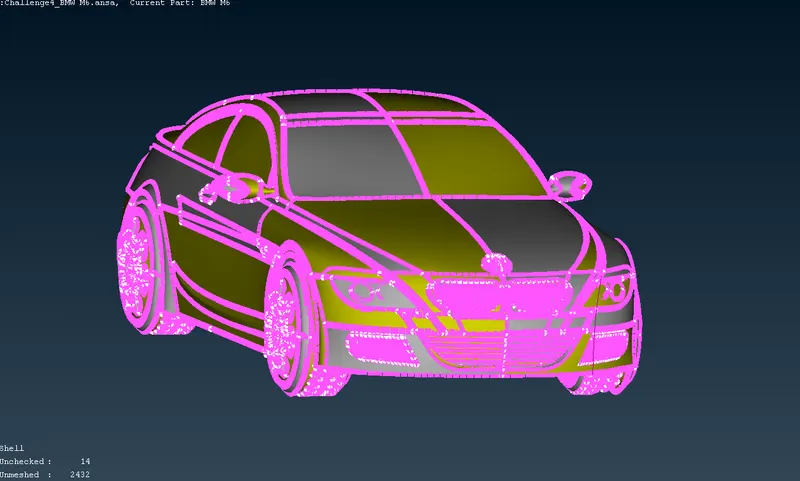
- On importing the intersection surfaces and red cons can be evidently seen in the below views.
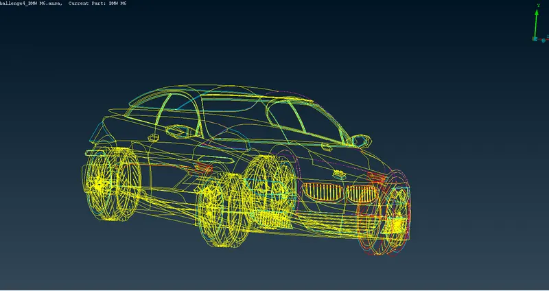
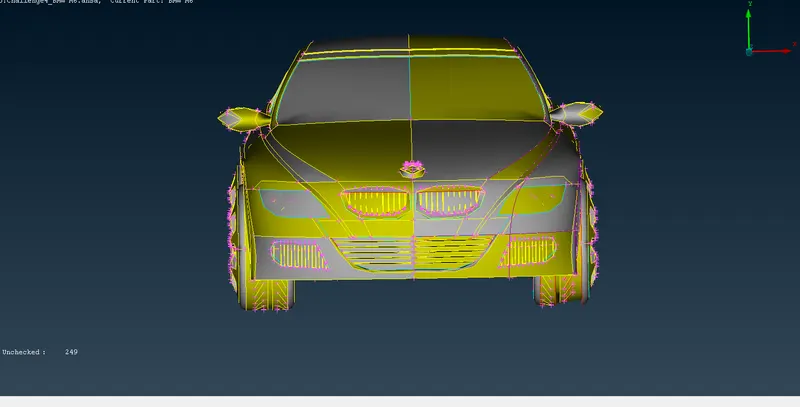
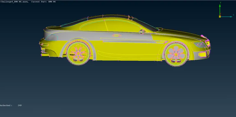
When noticed closely, the logo of BMW looks distorted. This is removed using the resolution set. The first image is the image before the resolution was set and the next image is after the resolution was set.
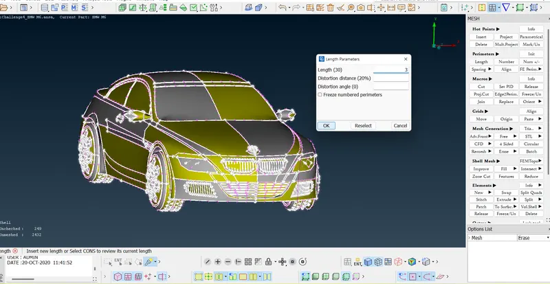
In this geometry, the Geometry Error Cleanup and Topo Cleanup are parallelly carried out.
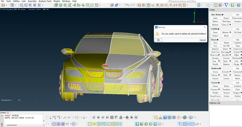
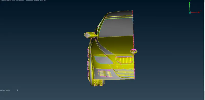
Prior to the Geometry Error Cleanup and Topo Cleanup, the car geometry is divided in half. Note that the logo cannot be divided in half as tit is assymmetric.
I. Geometry and Topo Cleanup of the Car
1. Grills
- The grills have a thickness, that is on the inside. Since the analysis of the car is supposed to be an external Aerodynamic CFD simulation, the internal thickness is extraneous. Hence, these surfaces are deleted and a zero-thickness grill surface is created.
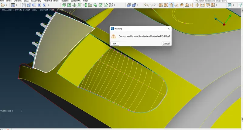
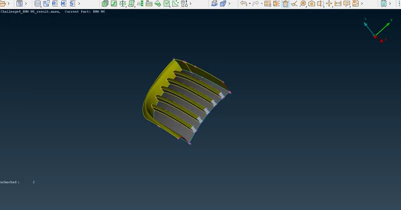
- The front grill surfaces are deleted in order to remove the thickness. This can be seen below.
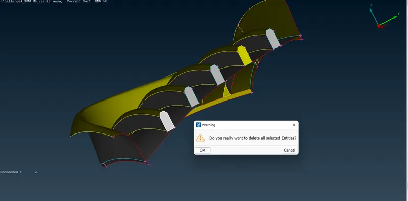
- Further, when closely observed, it can be noticed that the bottom faces of the front grills are not attached to the base surface. To attach this the CONS are projected on the surface. CONS > Project
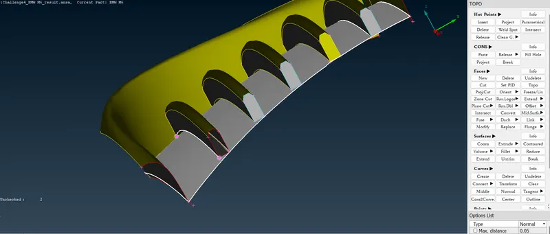
- Further, the present face is deleted and a new face is made with projected CON.
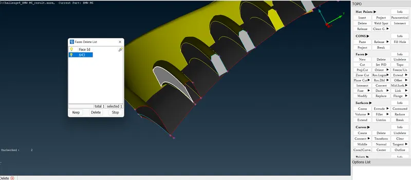
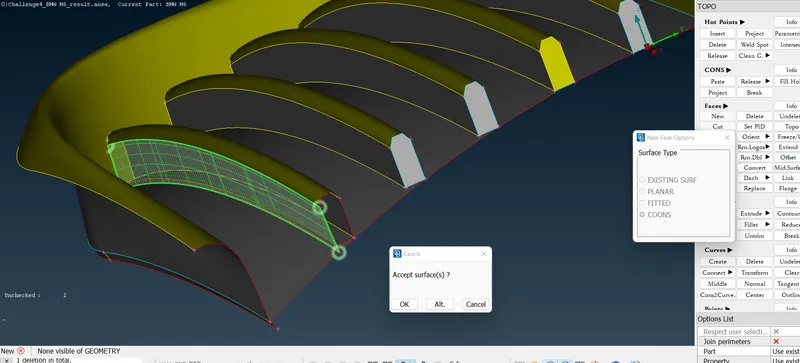
- Later the bottom surface is deleted to remove the width of the bottom surface completely.
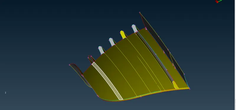
- After repeating with all the grill surfaces, the resolution is reset.
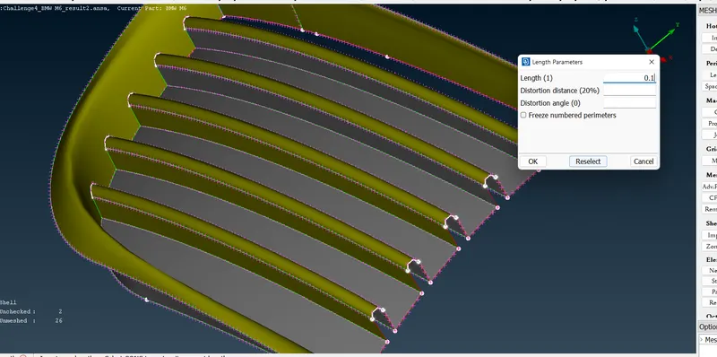
- Moving on to the next grill located at the extreme bottom right, an extra surface on the inside can be seen that ought to be trimmed for better meshing and CFD simulation.
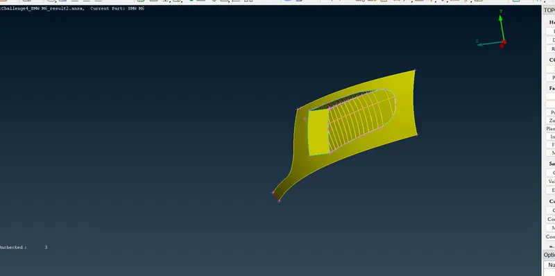
- In this grill, a surface is created from a fixed distance from the internal of the solid body. This surface would then be used to cut through the grills causing the irregularities of the surface to be addressed all at once rather than the individual projection of each grill surface.
- Initially, the parametric length is set. The parametric input adds HOT POINTS at a certain distance from the selected HOT POINTS. Then, a surface is created with the help of the CONS constructed from these HOT POINTS to intersect the grill surfaces uniformly.
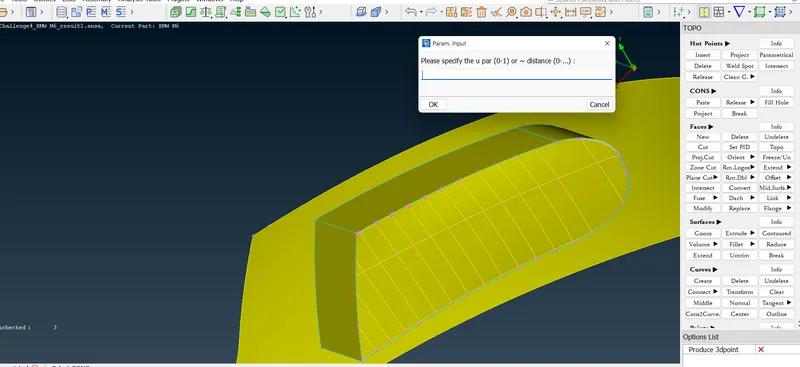
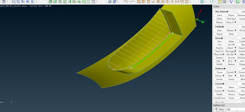
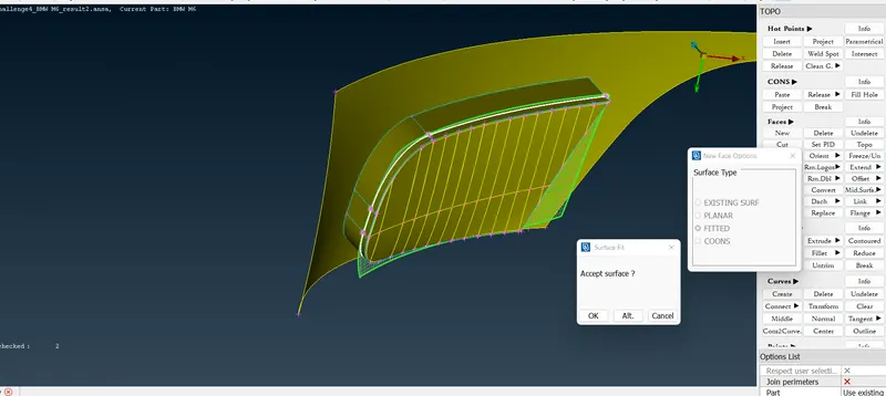
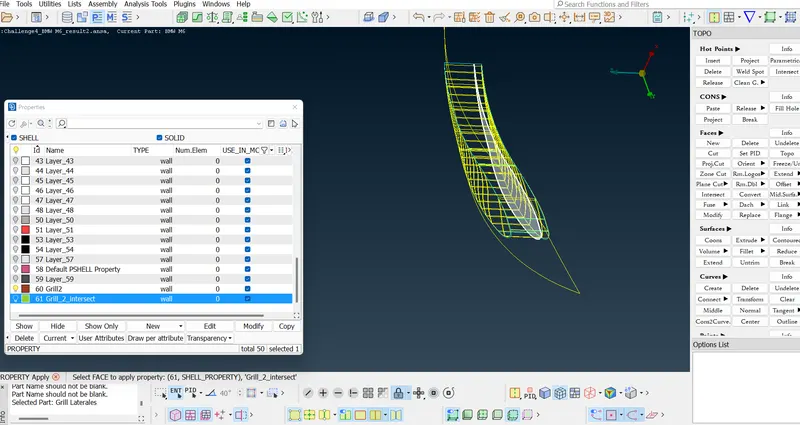
- The INTERSECT option is used under the Faces menu to delete unnecessary surfaces.
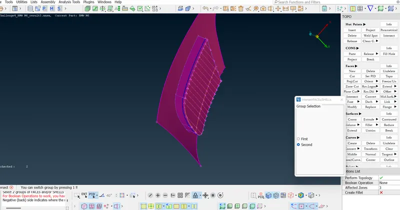
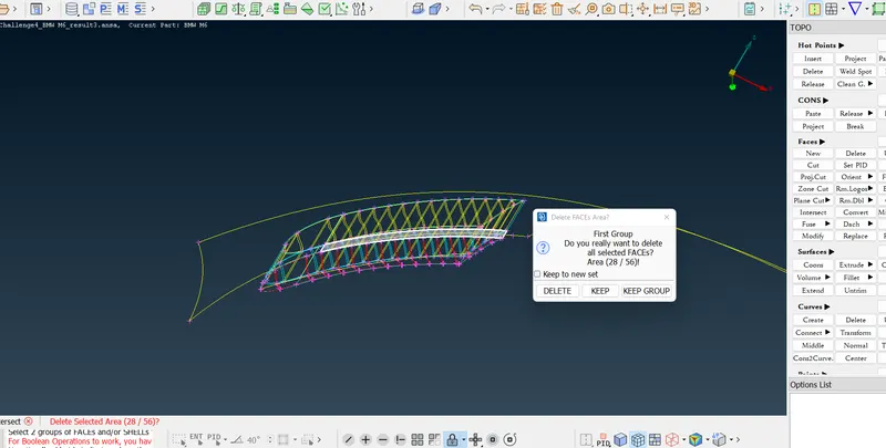
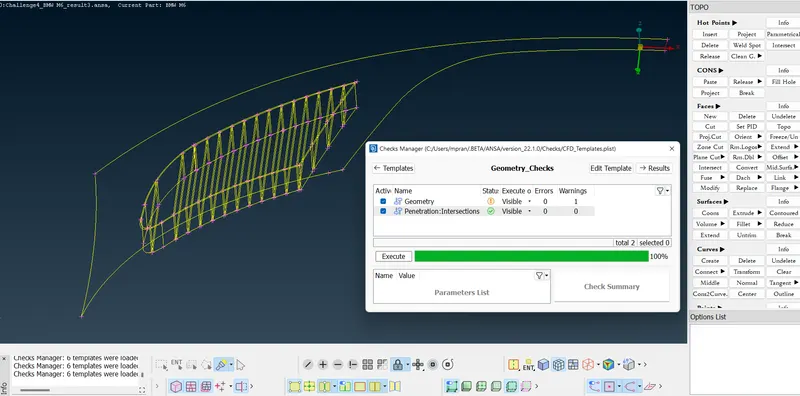
- Moving on to the third grill located just above the first grill, we find similar errors in the grill. Red CONS and Blue CONS are evidently visible in the geometry of the grill.
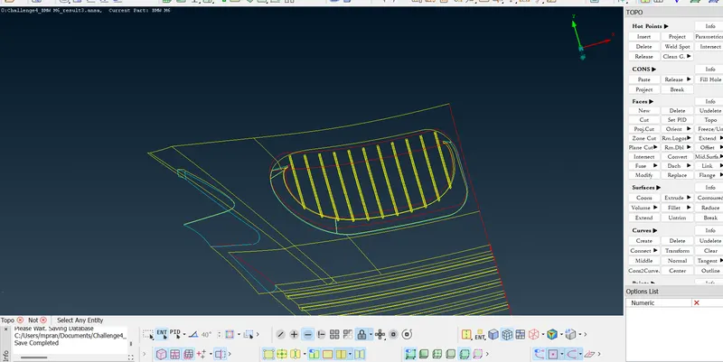
- The initial extraneous overlapping surfaces are deleted.
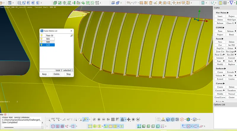
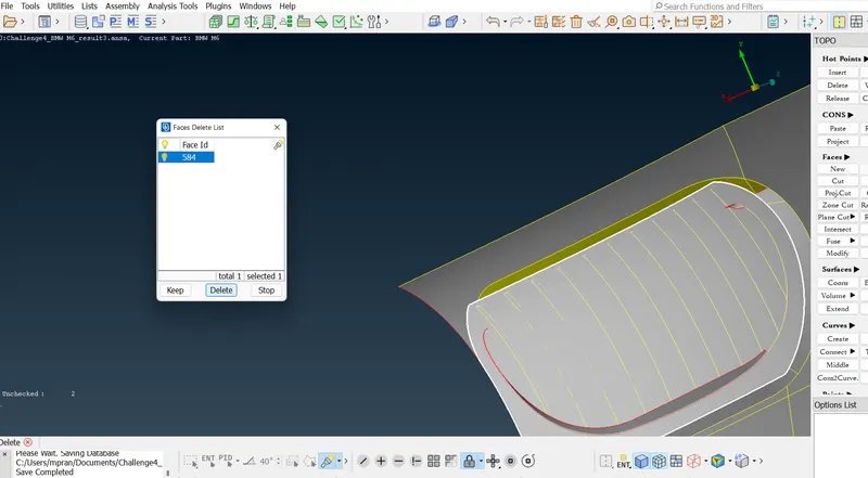
- After the deletion of extraneous surfaces, the surfaces of the necessary gaps are added.
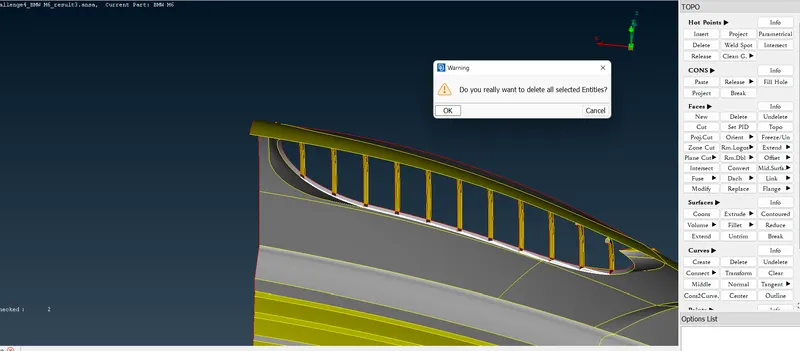
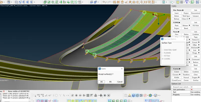
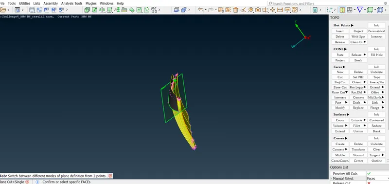
- Further, a PLANE CUT is done to cut all the grill surfaces in one plane all at once. The upper surface is deleted as a whole as it is unnecessary. This results in the reduction of the grills' length to that of the front surface.
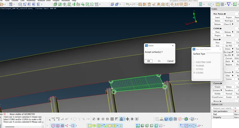
- Later, these grill surfaces are joined with the front surface to seal the total geometry. the joining happens with the help of the creation of new surfaces.
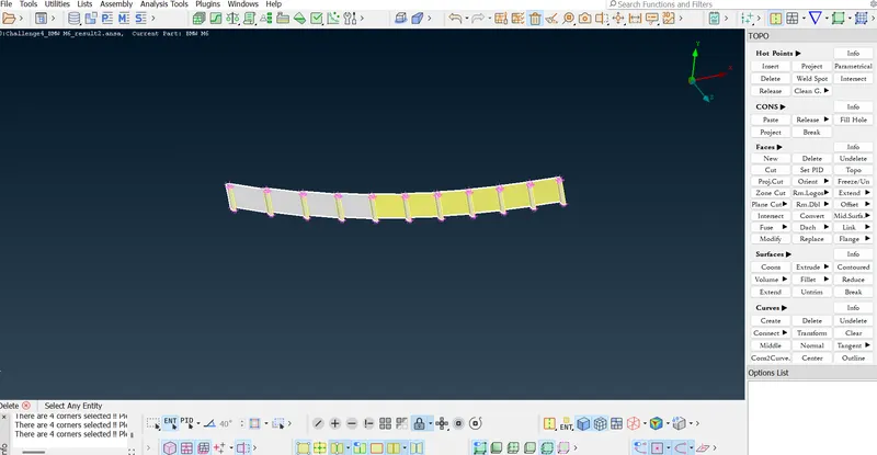
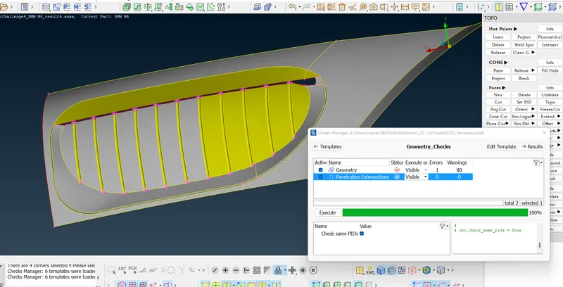
- After the deletion of the surfaces, an intersection error is detected when a geometry check is done. This penetration error is addressed before joining the grill and the front surface.
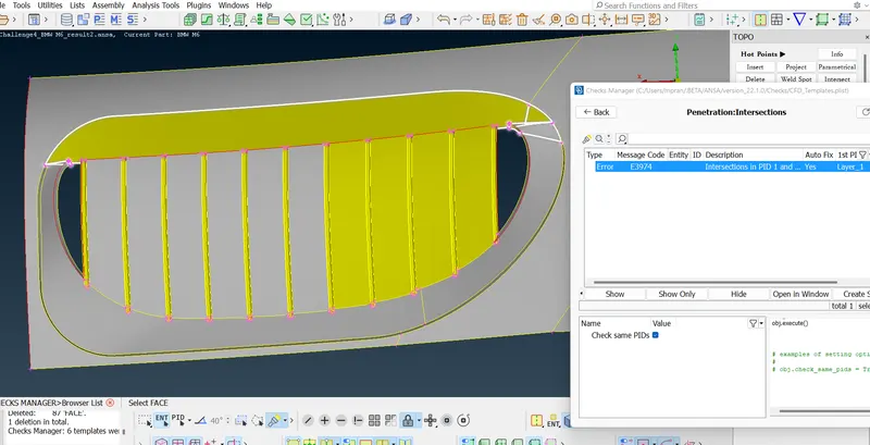
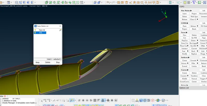
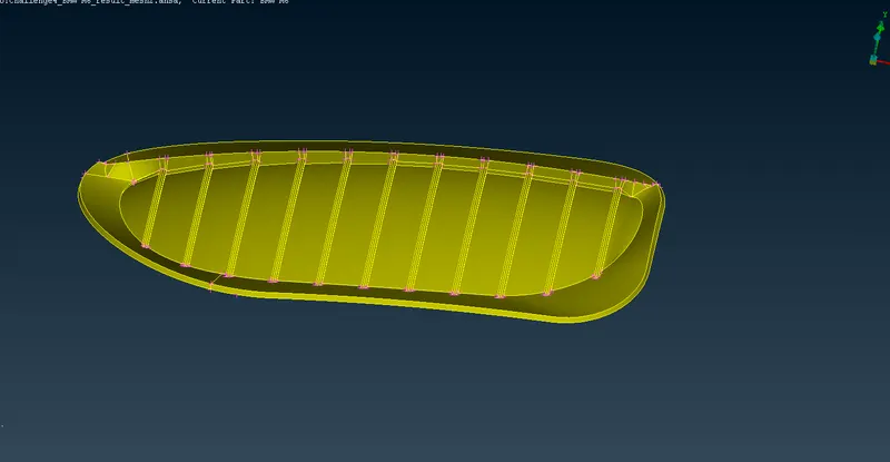
- Unnecessary surfaces and surfaces causing intersection errors are deleted. Hereafter new surfaces are added to completely seal the grill geometry. This can be seen in the following images.
2. Headlights
- The headlights have a certain thickness inside the car. This can be seen in the below image.
- However, as we know, for external flow simulation, internal width would unnecessary. Therefore the width is eliminated without changing the integrity of the external shape.
- The overlapping surfaces are deleted using the Delete > Faces option.
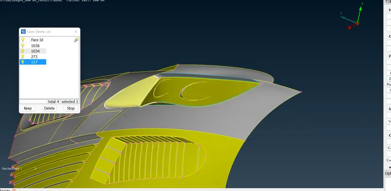
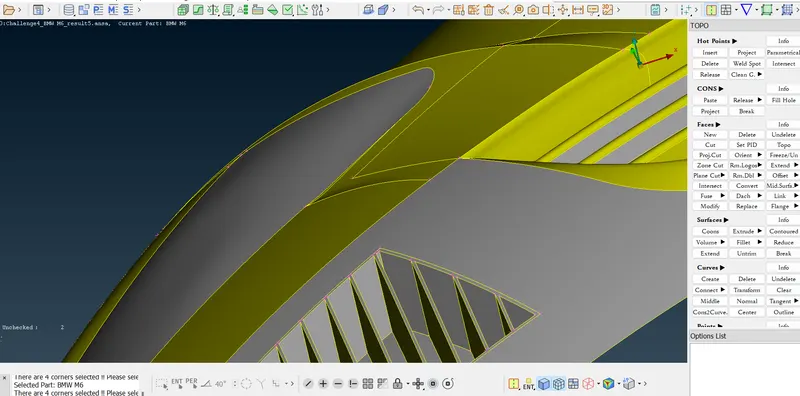
- The final geometry has no internal width. Note that the absence of internal surfaces in unnecessary geometries also prevents unrequired Volume Meshes.
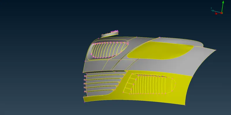
3. BMW Logo
- The logo is designed as an asymmetric entity. Therefore during the division of the car in half, the logo was left undisturbed.
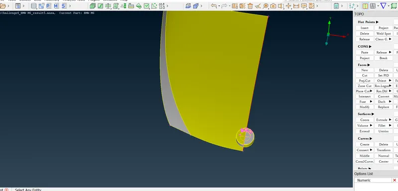
- The logo has intersection errors and unnecessary thickness that is removed by deleting the surfaces causing it using Delete > Faces.
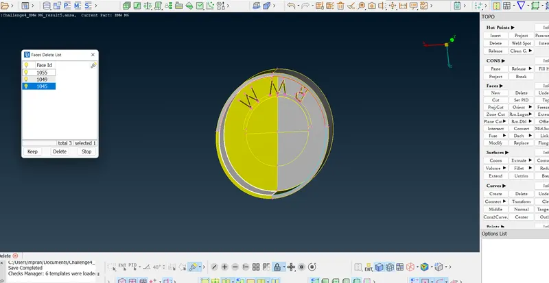
- After the deletion of internal surfaces, an open surface is created. That is filled using the creation of surfaces.
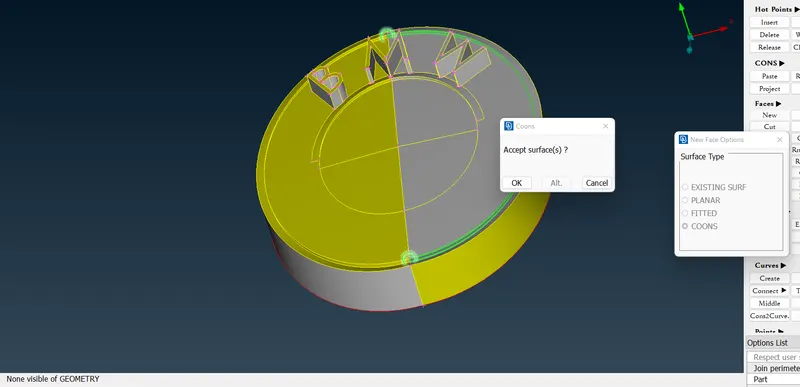
- After deletion of internal surfaces, the logo has red CONS at the bottom.
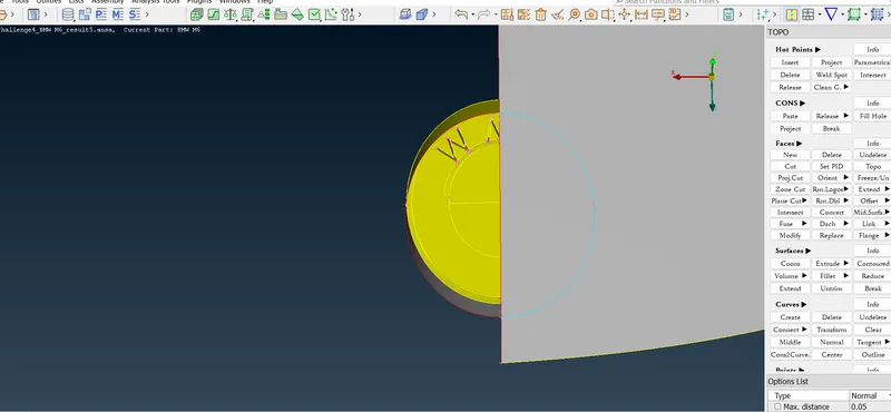
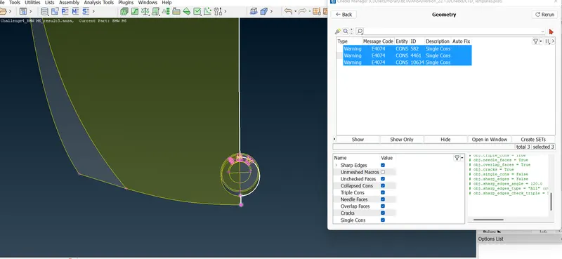
- The Red CONS are projected on the surface of the bonnet and then delete from the intersecting surface to remove the red CONS.
4. Side lights on Body
- The side light on the side body of the car has unrequired red CONS and surface thickness as can be seen below.
- Similar to the previous geometries, the unrequired surfaces are deleted.
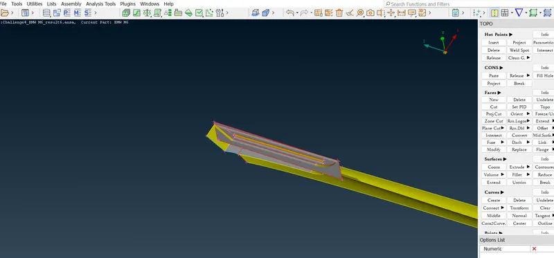
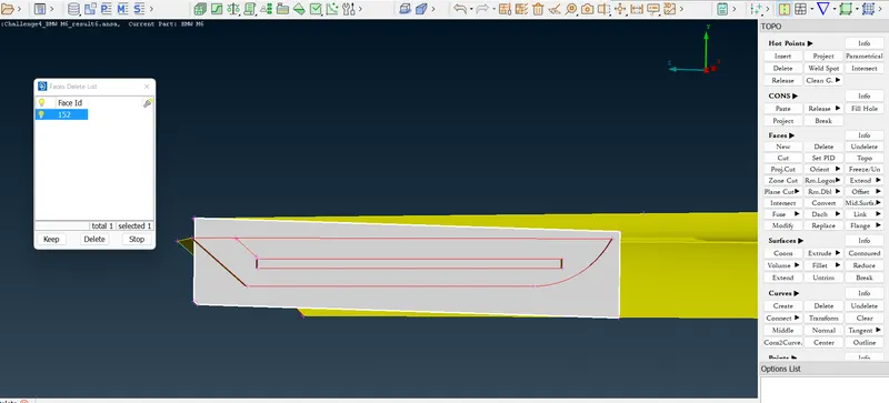
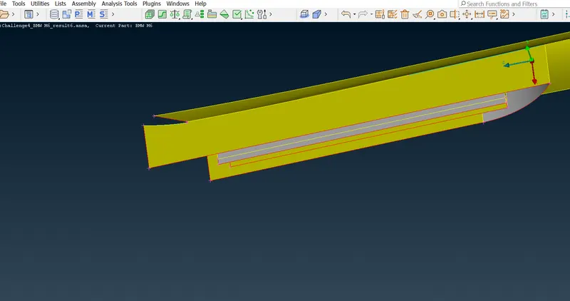
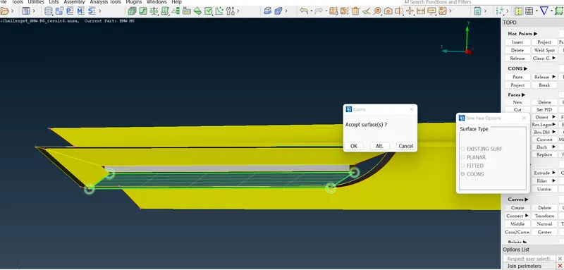
- The plane above the surface is projected on the below surface in order to create a sealed surface. After the plane is projected on the surface, a new surface is created. Similarly, other surfaces are created to seal the side of the body.
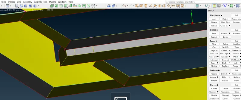
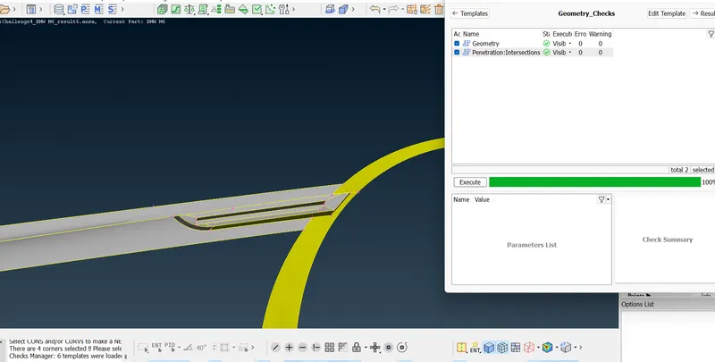
- After the addition of surfaces, zero intersection and geometry errors can be seen.
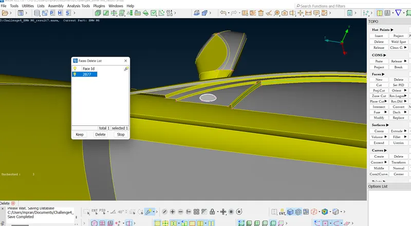
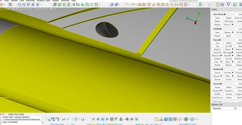
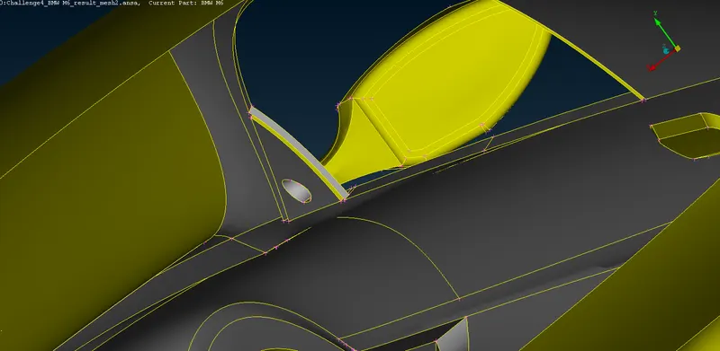
5. Optical Rear view mirror
- The side view mirror on the side of the body of the car, when observed closely depicts the irregularities in the geometry.
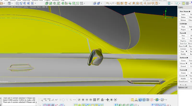
- The inner surfaces in the geometry are deleted to prevent the creation of unnecessary volumes.
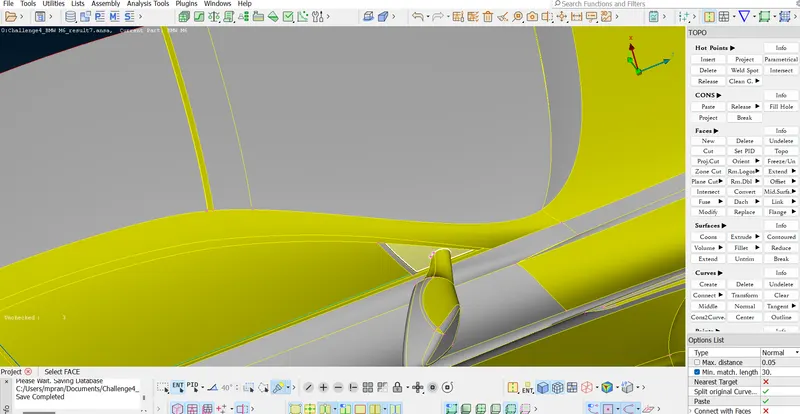
- Furthermore, the covered surface from the window side makes the mirror as a whole an unnecessary volume. Therefore, the mirror CONS are projected on the window surface. This in turn created a cut surface that on deletion eliminated the unnecessary volume.
5. Car Floor
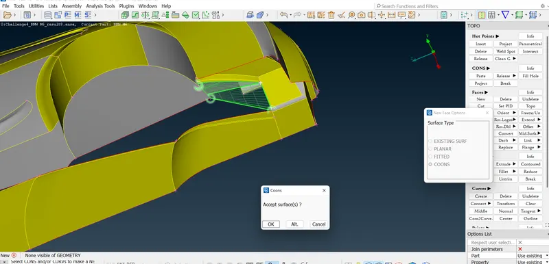
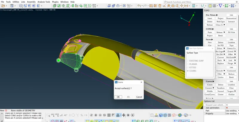
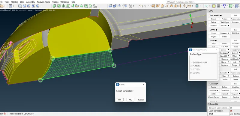
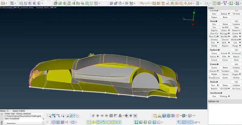
- The car floor is completely restructured due to the numerous red and Blue CONS that were causing the geometric and intersection errors.
- Curves were initially created to facilitate the free deletion of error-prone surfaces and at the same time preserve the integrity of the structure. These curves are created by Create > Curves.
- These curves in ANSA are the color code purple. These curves are finally deleted after the creation of uniform surfaces for the floor. The below images are a comprehensive guide on the same.
6. Tires
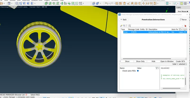
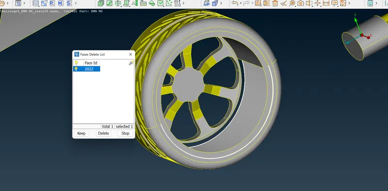
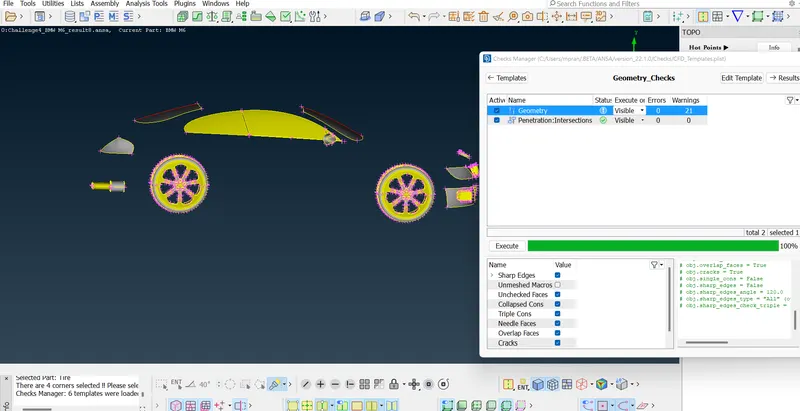
- The tires on close inspection and geometric check show both intersection errors and unnecessary internal thickness.
- The unnecessary thick surfaces are deleted and the intersection error as shown below is eliminated.
7. Additional surfaces
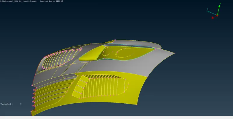
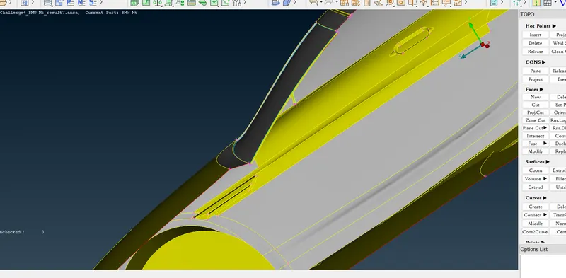
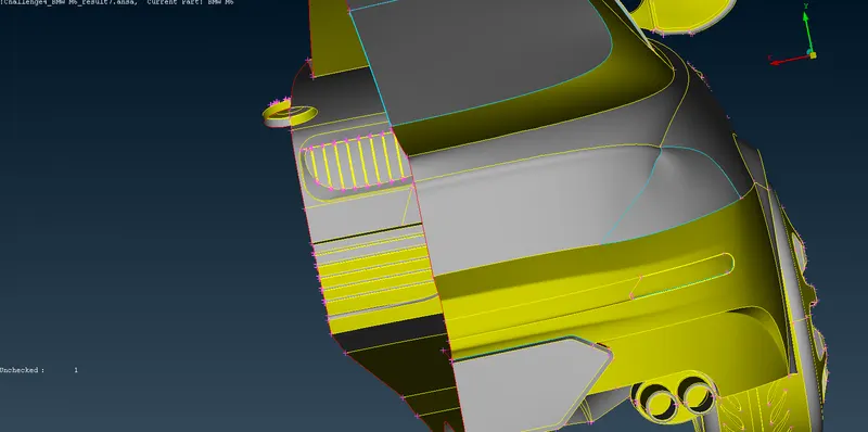
- The additional surfaces like exhaust, window panes, windshields, and car rims are cleaned for geometry and intersection. The primary steps in this process include the deletion of overlapping surfaces, unnecessary red CONS, tail lights and small topos in minor areas. of the car overall
- Below is an image of the windshield geometry cleaning.
- Below is the image for the taillights geometry cleaning.
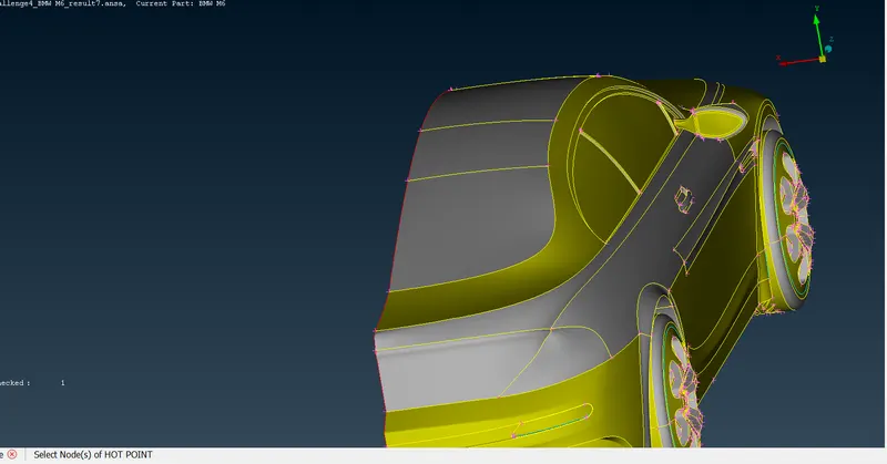
- Below is the image for the back floor geometry cleaning. The unnecessary CONS as seen in the image are deleted and reshaped.
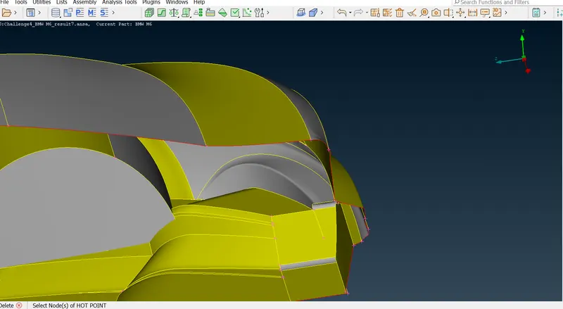
- The unnecessary CONS as can be seen are projected using first the Project option on the rim surface and then deleting the unnecessary surface.
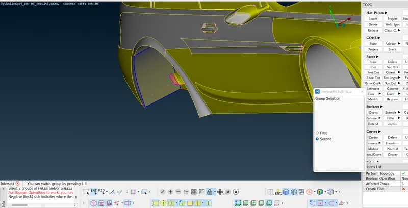
After all the Geometry and Topo Cleaning, the half car is geometry checked for errors.
Warnings in the geometry appear. A few of them are Convex, Concave, and Mixed CONS. These CONS are due to the creation of surfaces to seal surfaces. The Red CONS as can be seen are on the half part of the car. These red CONS go away when half of the car is replicated along the symmetry.
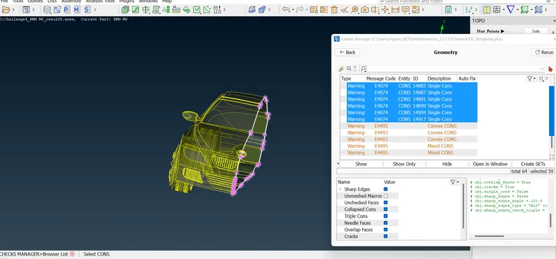
II. Surface Meshing of Car
In the surface meshing of the car, the primary objectives are to adhere to the target lengths, adhere to the quality criteria, and not deviate much from the same, and on these lines make a meshed structure using trias without any Off elements. On surface meshing the extreme lengths in Quality Criteria are always selected as higher extremes than the Mesh Parameter's lengths. This is in order to have an error-free mesh as extreme target lengths do not necessarily mean that element size in a few areas won't cross it, especially in the common perimeter zones.
Note that every Entity below is defined as a PID before being meshed.
1. BMW Logo
The meshing is BMW logo is set to the standard 1mm.
However, in this case there are some important points to be noted.
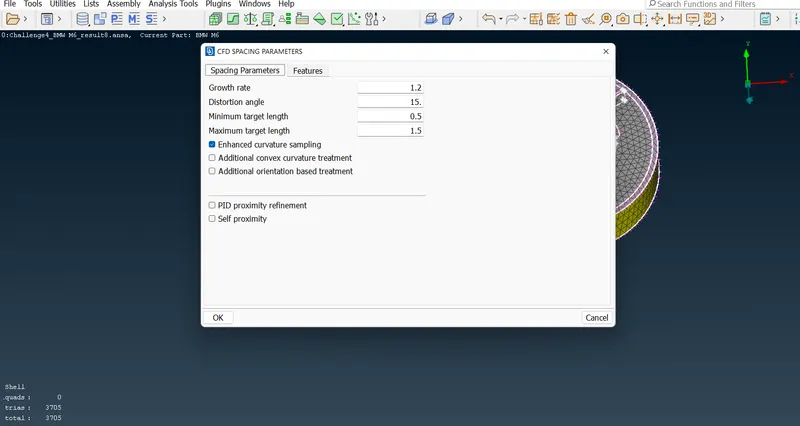
- The mesh target Length range is set by Mesh Parameters in the menu bar. Min. Length = 0.5mm and Max. Length = 1.5mm
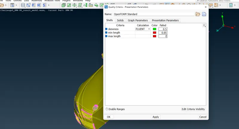
- Then the Mesh Quality Criteria is set in the menu bar. The overall quality criteria here used is Min. Length = 0.05mm, Max. Length = 7mm, and Skewness = 0.5.
Note - The quality criteria are set for the overall meshing. Therefore all the target lengths have been kept into consideration while designing the quality of the mesh.
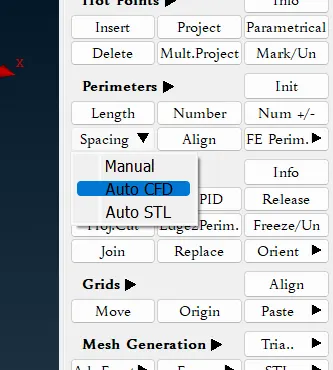
- The Macros and Perimeters are defined under the Mesh menu. Auto CFD > Spacing > Perimeters
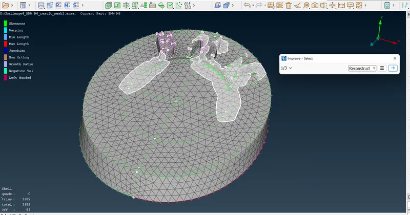
- After the meshing is performed, Off Elements are detected. These Off Elements are addressed by right-clicking on the Off in the bottom right and selecting the Improve option.
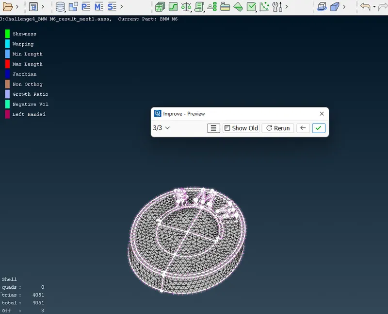
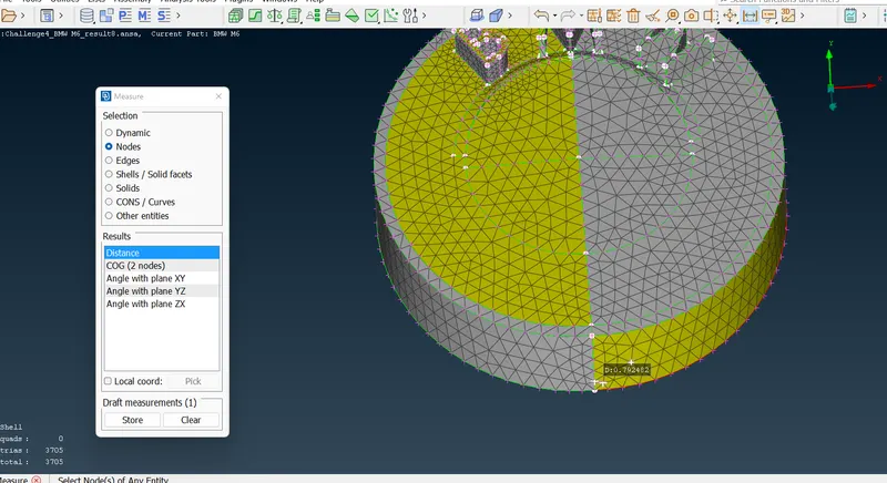
On measuring the distances with the Measuring tool in the menu bar it is noticed that the geometry fairly adheres to the target lengths.
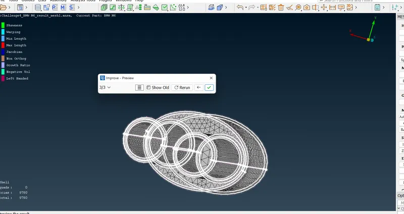
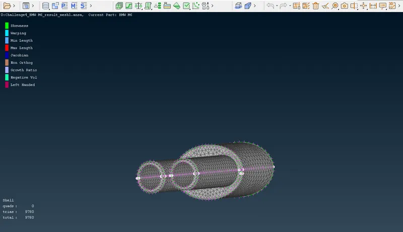
2. Silencer
- The given target length is 3mm.
- The Silencer is assigned Min. Length = 2.5mm and Max. Length = 3.5mm
- The Reconstruct tool is repeated as done previously.
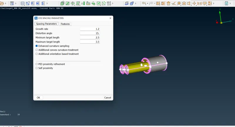
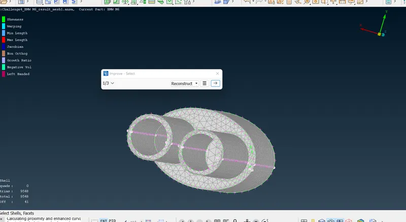
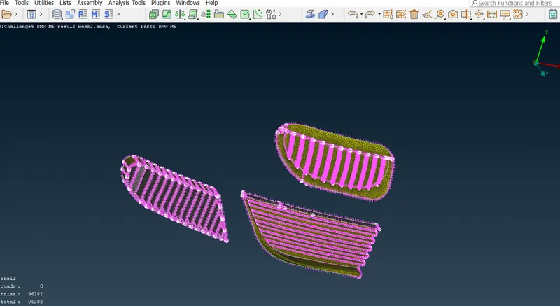
3.Grills
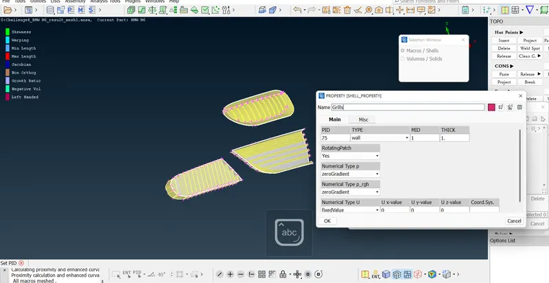
- The grills are first together defined as a PID. All the geometries are defined in a single PID.
- The given target length is 1mm.
- The Silencer is assigned Min. Length = 0.5mm and Max. Length = 1.5mm
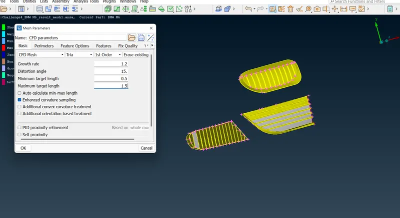
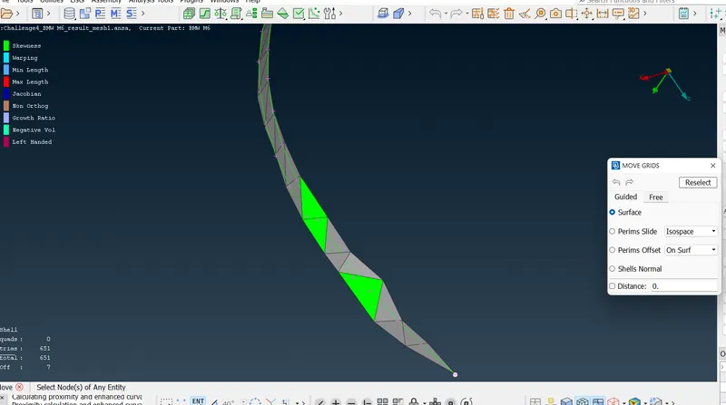
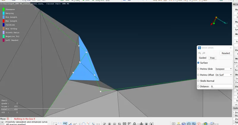
- In this particular case, even after the usage of the Reconstruct tool, there are a few Off elements. These Off Elements are addressed by Move Option > Grids > Mesh menu
- The grids are moved and adjusted accordingly to avoid the skewness error in this case.
- In case this method does not work, the mesh geometry beside the skewed elements can be Reshaped in the Improve option.
5. Windows and Tyres & Rims
- The Windows, Tyres & Rims, and Optical Rear View mirrors are defined as their respective PIDS.
- The given target length is 2mm.
- The Silencer is assigned Min. Length = 1.5mm and Max. Length = 2.5mm
- The same steps in reconstructing and reshaping are repeated in previous geometries.
6.Car Body
- The Windows, Tyres & Rims, and Optical Rear View mirrors are defined as their respective PIDS.
- The given target length is 3mm.
- The Silencer is assigned Min. Length = 2.5mm and Max. Length = 3.5mm
- The same steps in reconstructing and reshaping are repeated in previous geometries.
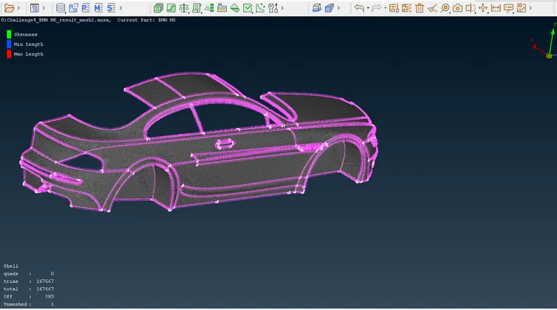
- However, we see a body left unmeshed in the car body. This happens majorly because of the definition Quality Criteria given along with the Mesh Parameters. The width of the body isn't exactly able to accommodate the element size.
- To address this problem a horizontal line is drawn across the body. This facilitates the meshing.
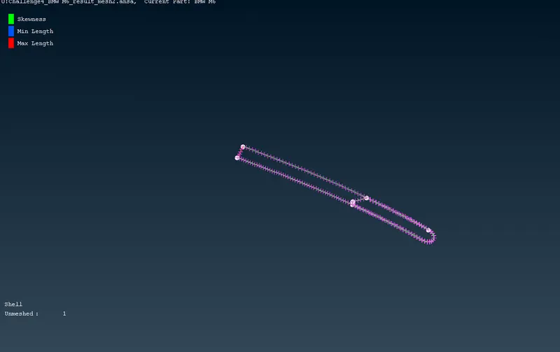
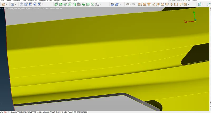
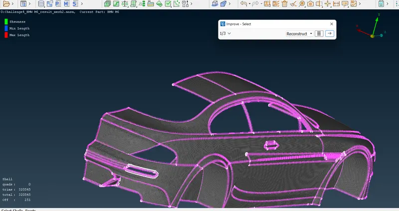
- Upon completing the meshing of the body, a problem of the common perimeter is encountered (which was predicted earlier). This causes the adjoining surfaces to lose the meshing due to differences in Target Lengths.
- This is addressed by using the Freeze option > Macros > Mesh menu.
- The other surfaces that lose the meshing are freely meshed later using the Free > Mesh Generation > Mesh menu.
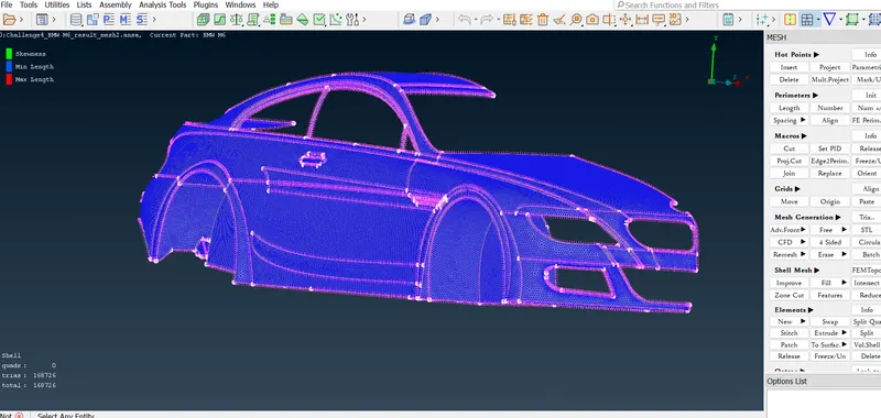
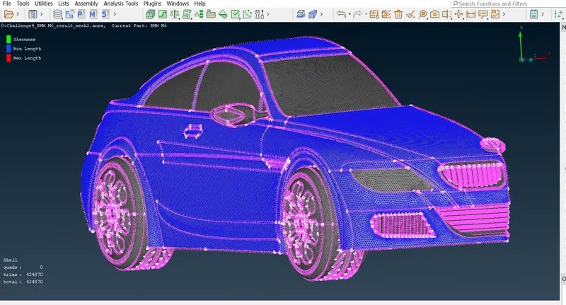
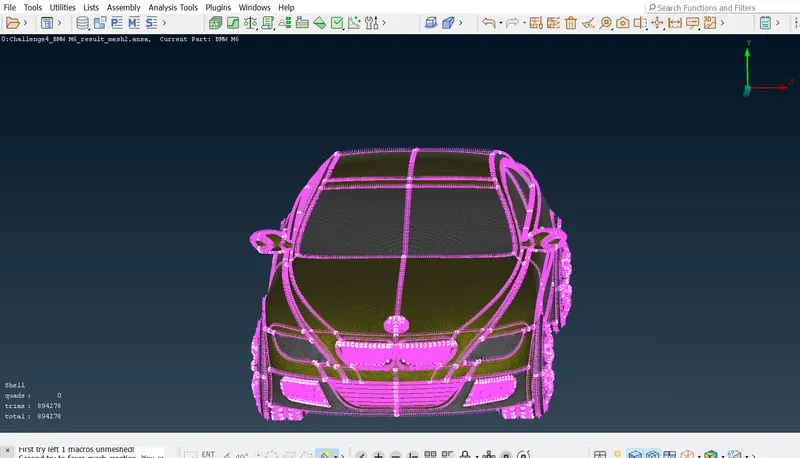
After the successful meshing and removal of Off elements, the whole surface of the body is duplicated along the symmetry.
This is done with help of Transform Tool in the top Menu bar. Here all the entities are copied along the symmetry in a 3-point system.
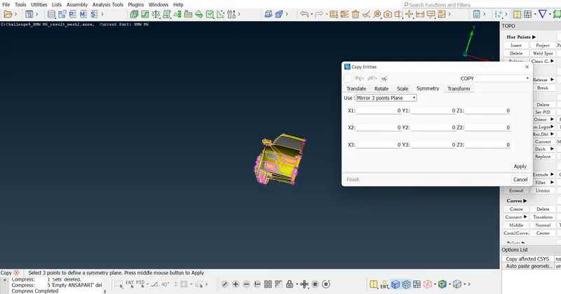
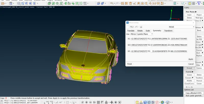
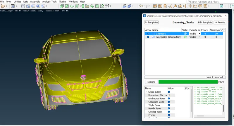
After the necessary removal of red CONS and minor cleaning of geometry, and removal of off elements, a check is done to ensure final geometric integrity and mesh quality.
III. Creation and Meshing of Wind Tunnel
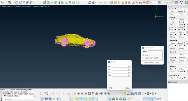
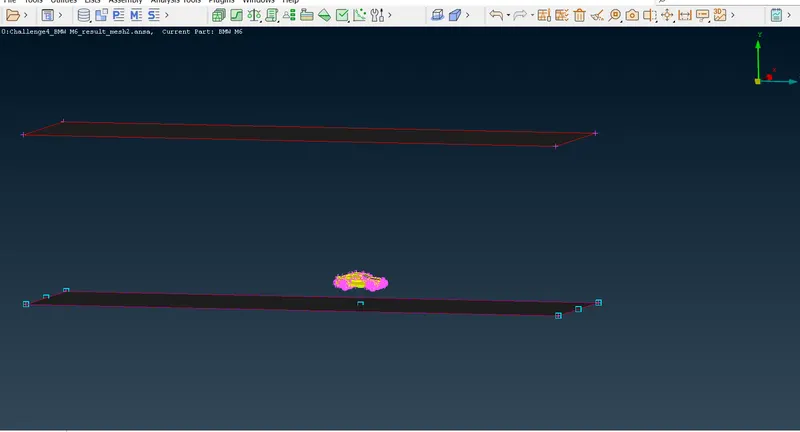
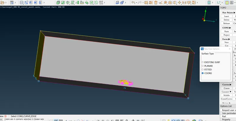
The creation of the Wind Tunnel is carried out through the dependency on the length of the car.
- Distance from the bottom of the car = 500mm
- Distance from the front of the car = 4x mm
- Distance from the back of the car = 6x mm
- Distance from the top of the car = 3x mm
- Distance from the sides of the car = x mm
where x= length of the car = 1310 mm.
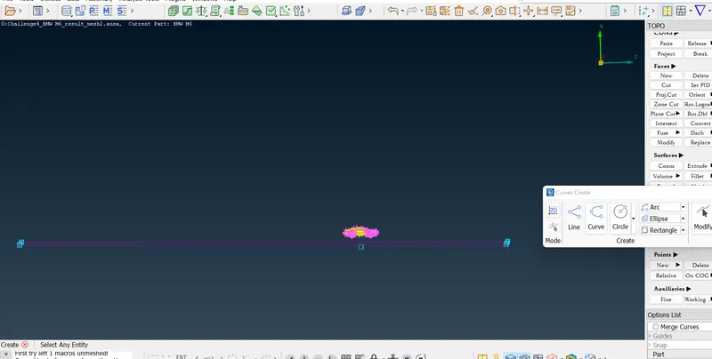
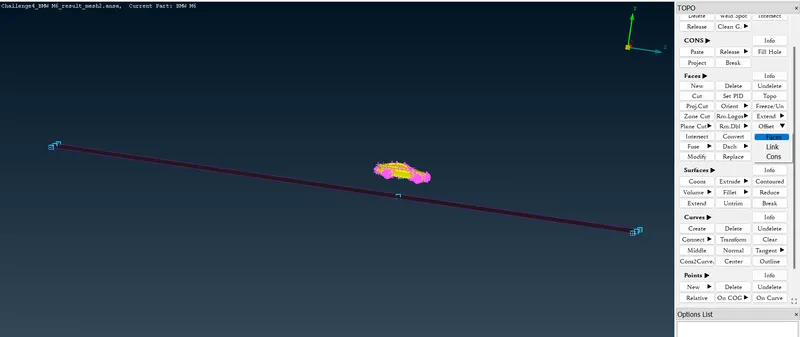
The geometry is created by adding Relative Points in the respective distances. These points are then joined by the Create > Curves. The surfaces are created using the New > Faces > COONS. Offset surfaces are created in accordance with the length directed through Offset > Faces.
After the creation of the geometry, the meshing is performed with different target lengths and biasing.
Bottom Surface = 25-45 mm
Top Surface = 90-110 mm
Side Surfaces = 20 - 110 mm Growth Rate = 1.2 with biasing from the bottom to the top.

RESULT AND DISCUSSION
The result shows the importance and best practices of surface meshing that is necessary for external fluid flow simulation. Few of the important takeaways are
- Elimination of unrequired volumes for surface meshing for external flow simulation
- Creation of Plane Cuts, Projections, Curve creation, and other tool features necessary for advanced geometric cleaning.
- Importance of Meshing Parameters and Quality criteria
- Importance of Growth Rate and BIasing to create a biased mesh.
Below is the google drive link to the solution. Please let me know in case of an error to access the drive link.
https://drive.google.com/file/d/17mJKMLfrL3yhytgL2cqi2dgOv5He-n1o/view?usp=sharing