Week 8 - Simulation of a backward facing step in OpenFOAM
Simulation of a backward facing step in OpenFOAM
INTRODUCTION
Studying the flow behaviour through various structures is an important subject for a CFD engineer. When fluids flow through different geometries they exhibit different velocity, pressure and flow properties. in this project, simulation of a flow through backward facing step is done by studying the flow of fluids through cemeteries that have sudden-changing shapes. The simulations are refined using multiple meshes - mesh grading factors inside the blockMeshDict file of blockMesh which is also used to create the geometric to be solved in OpenFOAM.
STEPS TO BE DONE
- Choosing a solver
- Selecting a solver tutorial to create geometry and meshing.
- Setting up case
- Assigning boundary conditions
- Assigning initial conditions
- Post processing the result
- Plotting the result
CREATING GEOMETRY
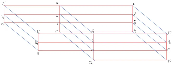
Software file called blockMeshDict in the tutorials system folder creates the geometry and mesh, hence this is modified to create the backward facing step. Since blockMeshDict file can create geometries only in block format, we created the blocks and indexed the vertices as shown below.
3. Setting up case
We now setup the case in blockMeshDict file by assigning boundary & wall condition, time step and end time in ControlDict file and initial condition in the velocity and pressure file.
Once the geometry created, we assign boundary conditions, for the flow to take place within the geometry.
BlockMesh and geometry creation methods
Create 21 vertices in blockMesh file as shown in diagram and make suitable cordinates to it
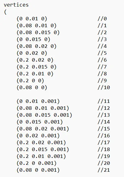
Create blocks as shown in commands below
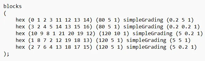
While creating block, we should look the geometry from positive axis direction towards negative axis direction.
Then name the blocks in anti clock wise direction or do it as per right handed cordinate direction.
When naming inlets, outlets and walls, then also we should look any geometry from outside and apply righty hand cordinate system to do the name.
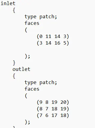
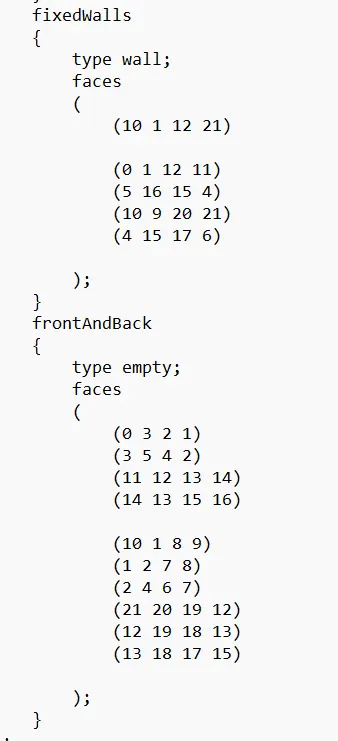
Then come to the meshing part
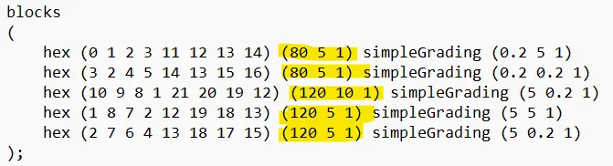
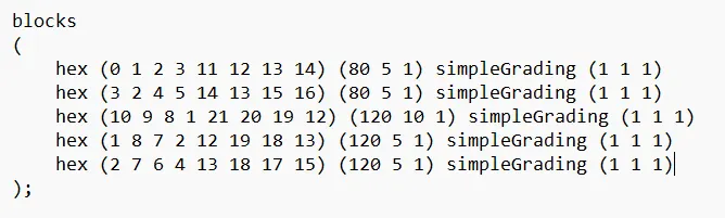
For block 1 and 2, I put 80 cells
For block 3,4 and 5, I put 120 cells
Now lets do the grading part
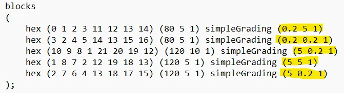
The grading is given by
grading = last cell size/ first cell size.
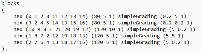
For blocks 1 and 2, the last cells are smaller than first cells by a factor of 0.2.
For blocks 3,4 and 5, the first cells are smaller than last cells by a factor of 0.2 or the last cells are bigger than first cells by a factor of 0.2. It is because 1/0.2 = 5.
The cells after grading is shown below

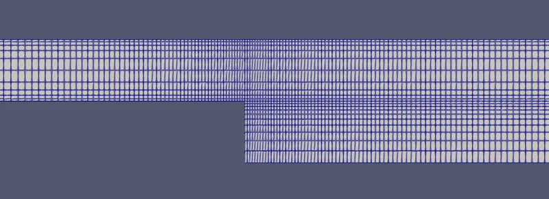
If we do not use grading, we can put it as (1 1 1), such that all cells are equally spaced

Mesh specification
- Number of cells along x- direction=200Number of cells along x- direction=200
- Number of cells along y direction=20Number of cells along y direction=20
- Number of cells along z direction=1Number of cells along z direction=1
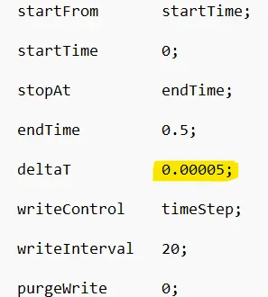
After this we change the time step in the controlDict file.
blockMeshDict file for the geometry
a)for grading factor 1
/*--------------------------------*- C++ -*----------------------------------*\
  =========                 |
  \\      /  F ield         | OpenFOAM: The Open Source CFD Toolbox
   \\    /   O peration     | Website:  https://openfoam.org
    \\  /    A nd           | Version:  10
     \\/     M anipulation  |
\*---------------------------------------------------------------------------*/
FoamFile
{
    format      ascii;
    class       dictionary;
    object      blockMeshDict;
}
// * * * * * * * * * * * * * * * * * * * * * * * * * * * * * * * * * * * * * //

convertToMeters 1;

vertices
(
    (0 0.01 0)			//0
    (0.08 0.01 0)			//1
    (0.08 0.015 0)		//2
    (0 0.015 0)			//3
    (0.08 0.02 0)			//4
    (0 0.02 0)			//5
    (0.2 0.02 0)			//6
    (0.2 0.015 0)			//7
    (0.2 0.01 0)			//8
    (0.2 0 0)			//9
    (0.08 0 0)			//10

    (0 0.01 0.001)		//11
    (0.08 0.01 0.001)		//12
    (0.08 0.015 0.001)		//13
    (0 0.015 0.001)		//14
    (0.08 0.02 0.001)		//15
    (0 0.02 0.001)		//16
    (0.2 0.02 0.001)		//17
    (0.2 0.015 0.001)		//18
    (0.2 0.01 0.001)		//19
    (0.2 0 0.001)			//20
    (0.08 0 0.001)		//21

);

blocks
(
    hex (0 1 2 3 11 12 13 14) (80 5 1) simpleGrading (1 1 1)
    hex (3 2 4 5 14 13 15 16) (80 5 1) simpleGrading (1 1 1)
    hex (10 9 8 1 21 20 19 12) (120 10 1) simpleGrading (1 1 1)
    hex (1 8 7 2 12 19 18 13) (120 5 1) simpleGrading (1 1 1)
    hex (2 7 6 4 13 18 17 15) (120 5 1) simpleGrading (1 1 1)
);

boundary
(
inlet
    {
        type patch;
        faces
        (
            (0 11 14 3)
            (3 14 16 5)

        );
    }
    outlet
    {
        type patch;
        faces
        (
            (9 8 19 20)
            (8 7 18 19)
            (7 6 17 18)
        );
    }
    fixedWalls
    {
        type wall;
        faces
        (
            (10 1 12 21)

		(0 1 12 11)
            (5 16 15 4)
            (10 9 20 21)
            (4 15 17 6)

        );
    }
    frontAndBack
    {
        type empty;
        faces
        (
            (0 3 2 1)
            (3 5 4 2)
            (11 12 13 14)
            (14 13 15 16)

            (10 1 8 9)
            (1 2 7 8)
            (2 4 6 7)
            (21 20 19 12)
            (12 19 18 13)
            (13 18 17 15)

        );
    }
);

mergePatchPairs
(
);

// ************************************************************************* //
b)for grading factor 0.2
/*--------------------------------*- C++ -*----------------------------------*\
  =========                 |
  \\      /  F ield         | OpenFOAM: The Open Source CFD Toolbox
   \\    /   O peration     | Website:  https://openfoam.org
    \\  /    A nd           | Version:  10
     \\/     M anipulation  |
\*---------------------------------------------------------------------------*/
FoamFile
{
    format      ascii;
    class       dictionary;
    object      blockMeshDict;
}
// * * * * * * * * * * * * * * * * * * * * * * * * * * * * * * * * * * * * * //

convertToMeters 1;

vertices
(
    (0 0.01 0)			//0
    (0.08 0.01 0)			//1
    (0.08 0.015 0)		//2
    (0 0.015 0)			//3
    (0.08 0.02 0)			//4
    (0 0.02 0)			//5
    (0.2 0.02 0)			//6
    (0.2 0.015 0)			//7
    (0.2 0.01 0)			//8
    (0.2 0 0)			//9
    (0.08 0 0)			//10

    (0 0.01 0.001)		//11
    (0.08 0.01 0.001)		//12
    (0.08 0.015 0.001)		//13
    (0 0.015 0.001)		//14
    (0.08 0.02 0.001)		//15
    (0 0.02 0.001)		//16
    (0.2 0.02 0.001)		//17
    (0.2 0.015 0.001)		//18
    (0.2 0.01 0.001)		//19
    (0.2 0 0.001)			//20
    (0.08 0 0.001)		//21

);

blocks
(
    hex (0 1 2 3 11 12 13 14) (80 5 1) simpleGrading (0.2 5 1)
    hex (3 2 4 5 14 13 15 16) (80 5 1) simpleGrading (0.2 0.2 1)
    hex (10 9 8 1 21 20 19 12) (120 10 1) simpleGrading (5 0.2 1)
    hex (1 8 7 2 12 19 18 13) (120 5 1) simpleGrading (5 5 1)
    hex (2 7 6 4 13 18 17 15) (120 5 1) simpleGrading (5 0.2 1)
);

boundary
(
inlet
    {
        type patch;
        faces
        (
            (0 11 14 3)
            (3 14 16 5)

        );
    }
    outlet
    {
        type patch;
        faces
        (
            (9 8 19 20)
            (8 7 18 19)
            (7 6 17 18)
        );
    }
    fixedWalls
    {
        type wall;
        faces
        (
            (10 1 12 21)

		(0 1 12 11)
            (5 16 15 4)
            (10 9 20 21)
            (4 15 17 6)

        );
    }
    frontAndBack
    {
        type empty;
        faces
        (
            (0 3 2 1)
            (3 5 4 2)
            (11 12 13 14)
            (14 13 15 16)

            (10 1 8 9)
            (1 2 7 8)
            (2 4 6 7)
            (21 20 19 12)
            (12 19 18 13)
            (13 18 17 15)

        );
    }
);

mergePatchPairs
(
);

// ************************************************************************* //
ControlDict file for both the cases are same which is given below
/*--------------------------------*- C++ -*----------------------------------*\
  =========                 |
  \\      /  F ield         | OpenFOAM: The Open Source CFD Toolbox
   \\    /   O peration     | Website:  https://openfoam.org
    \\  /    A nd           | Version:  10
     \\/     M anipulation  |
\*---------------------------------------------------------------------------*/
FoamFile
{
    format      ascii;
    class       dictionary;
    location    "system";
    object      controlDict;
}
// * * * * * * * * * * * * * * * * * * * * * * * * * * * * * * * * * * * * * //

application     icoFoam;

startFrom       startTime;

startTime       0;

stopAt          endTime;

endTime         0.5;

deltaT          0.00005;

writeControl    timeStep;

writeInterval   20;

purgeWrite      0;

writeFormat     ascii;

writePrecision  6;

writeCompression off;

timeFormat      general;

timePrecision   6;

runTimeModifiable true;


// ************************************************************************* //
Initial conditions:
Initial conditions are velocity and pressure as per the boundary conditions and the study we wish to perform, the initial conditions are as follows:
For velocity
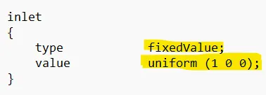
The inlet velocity conditions are changed as shown below
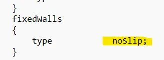
noSlip conditions are assigned to walls as shown below
C++ code is shown below
/*--------------------------------*- C++ -*----------------------------------*\
  =========                 |
  \\      /  F ield         | OpenFOAM: The Open Source CFD Toolbox
   \\    /   O peration     | Website:  https://openfoam.org
    \\  /    A nd           | Version:  10
     \\/     M anipulation  |
\*---------------------------------------------------------------------------*/
FoamFile
{
    format      ascii;
    class       volVectorField;
    object      U;
}
// * * * * * * * * * * * * * * * * * * * * * * * * * * * * * * * * * * * * * //

dimensions      [0 1 -1 0 0 0 0];

internalField   uniform (0 0 0);

boundaryField
{
    inlet
    {
        type            fixedValue;
        value           uniform (1 0 0);
    }

    outlet
    {
        type            zeroGradient;
    }
    fixedWalls
    {
        type            noSlip;
    }

    frontAndBack
    {
        type            empty;
    }
}

// ************************************************************************* //
For pressure
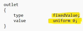
The outlet value is changed as shown below, so that flow should occur. If there is pressure difference between inlet and outlet, then only the flow will occur
C++ code is shown below
/*--------------------------------*- C++ -*----------------------------------*\
  =========                 |
  \\      /  F ield         | OpenFOAM: The Open Source CFD Toolbox
   \\    /   O peration     | Website:  https://openfoam.org
    \\  /    A nd           | Version:  10
     \\/     M anipulation  |
\*---------------------------------------------------------------------------*/
FoamFile
{
    format      ascii;
    class       volScalarField;
    object      p;
}
// * * * * * * * * * * * * * * * * * * * * * * * * * * * * * * * * * * * * * //

dimensions      [0 2 -2 0 0 0 0];

internalField   uniform 0;

boundaryField
{
inlet
    {
        type            zeroGradient;
    }

    outlet
    {
        type            fixedValue;
        value           uniform 0;
    }

    fixedWalls
    {
        type            zeroGradient;
    }

    frontAndBack
    {
        type            empty;
    }
}

// ************************************************************************* //
4. Post processing the result
After running the simulation using blockMesh command we post process the result in paraView software.
For grading factor 11
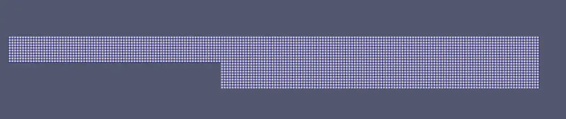
Mesh generated
Velocity contour for grading 11
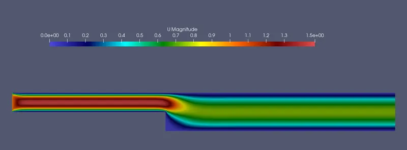
The block images above are part of blockMeshDict file and shows the mesh grading and grading factor set on the geometry. We can observe the mesh looks finer and once the mesh is created. We can now run the simulation in paraView to observe the result. How It looks visually and how the flow takes place in it.
For grading factor 0.20.2
Mesh generated

Velocity contour:
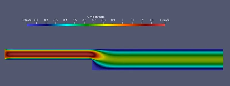
From the simulation, we can observe that the velocity magnitude at inlet is higher but it suddenly drops after 0.085m0.085� because sudden increase in flow area. Also, we can observe the blue line in velocity contour on every fixed wall because magnitude of velocity is zero in no slip condition at boundary.
5. Comparing the plots
As the fluid flows through a pipe, a boundary layer is created against the walls of the pipe and it builds perpendicular to it, velocity is slow at the surface and goes on increasing as we move away from the wall.
From the contours above, we can see that before the step reason the fluids has no obstruction or geometry changes. For x=0.085�=0.085m� velocity behaves like:
Output plot for grading factor 11
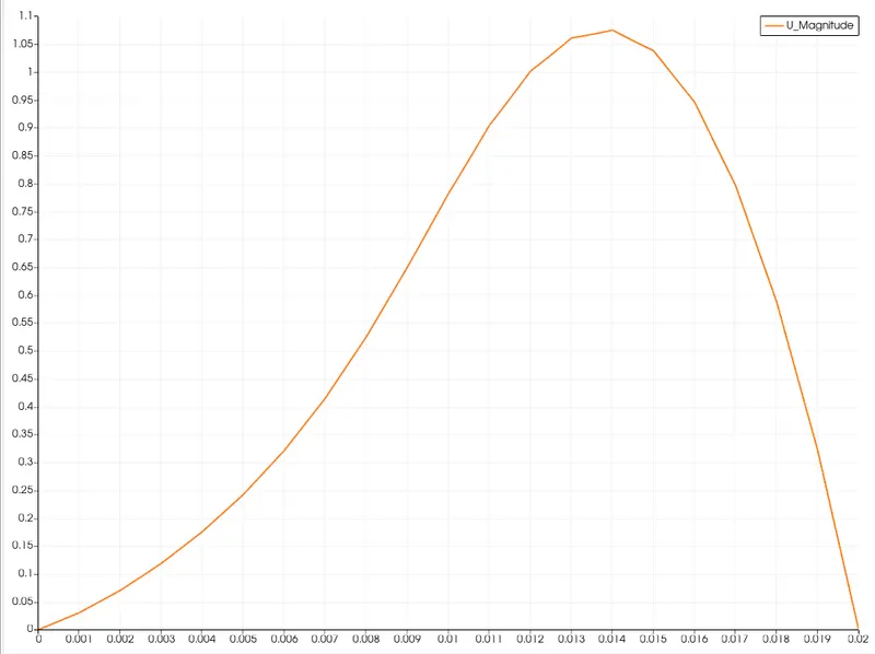
The profile looks closer to a parabolic shape with the endpoints as boundaries and mid-region where the flow speed is maximum. Once the fluid passes through the step the velocity profile appears.
Output plot for grading factor 0.20.2
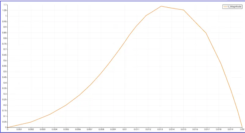
As the fluid crosses the step reason, the area increases. Now looking at the reason in graph from 00 to 0.20.2 The top part of the geometry after step, comparing two upstream reason at x=0.085m�=0.085� due to increased area. The fluid expands its area of flow.
For the both grading factors, as the mesh becomes more finer at 0.20.2 we can see the velocity drop curve, it's noticeably wider. We can get the smooth curve if the mesh become more finer
Overall the velocity magnitude profile gives similar result in general but with a mesh grading factor its observed that finer results can be obtained with the finer mesh and more accuracy can be aimed in the solution.