Week 1: Channel flow simulation using CONVERGE CFD
-: SIMULATING CHANNEL FLOW USING CONVERGE CFD :-
l. INTRODUCTION:-
Simulation is the creation of a model that can be manipulated ,logicallyto decide how to the physical world works
channel flow is an internal flow in which the confining wall changes the hydrodynamic structure of the flow from an arbitrary state at the channel inlet to a certain state at the outlet the simples illustation of internal flow is a laminar flow in a circular tube while a turbulent flow in the rotor of a centrifugal compressor is an example of the most intricately shaped internal flow engineering devices employ channel with cross section of various geometrical shapes
in this project converge studio was used to estabilsh a workingidea of airflow simulation through a channel flow under certain parameters which will be elaborated systematically in this report
ll. OBJECTIVE:-
Setup channel flow simulation
Run simulation for 3 different mesh sizes
plot velocity and pressure contours for all 3 mesh sizes
show plots for velocity ,pressure mass flow rate and total cell count for all 3 mesh sizes
lll. PROCEDURE:-
GEOMATRY:
Creating a geometry using the creation tool of converge studio
running diagnosis to chek if there are any open edges or faces
checking the orientation of normals
the normals should be such that their orientation is poninting towards the fluid flow
BOUNDARY FLAGGING:-
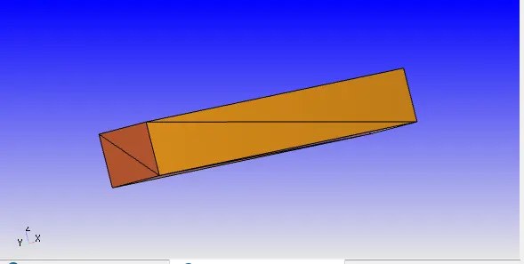
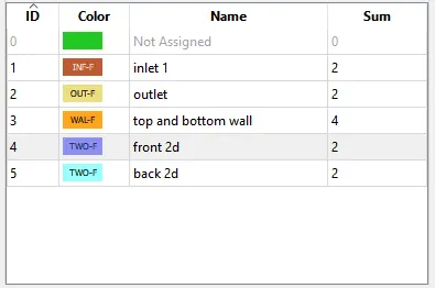
The boundaries are flageed. the converge studio basically uses triangular block to creat geometry so by selecting the triangles boundaries are flagged
- inlet
- outlet
- top and bottom walls
- front2D
- back2D
CASE SETUP:-
APPLICATION TYPE - time based
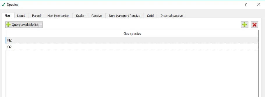
materials - air
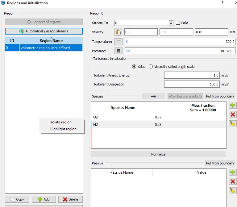
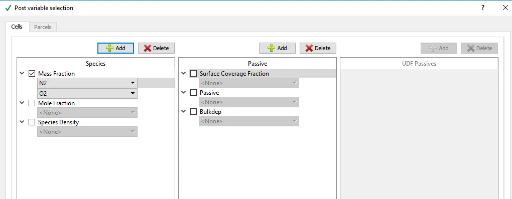
gas simulation is checked with the species O2 and N2
. simulationparameter -
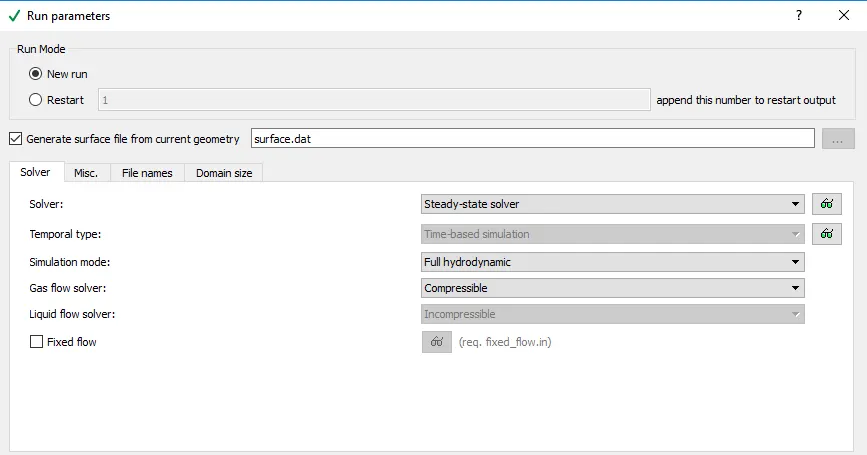
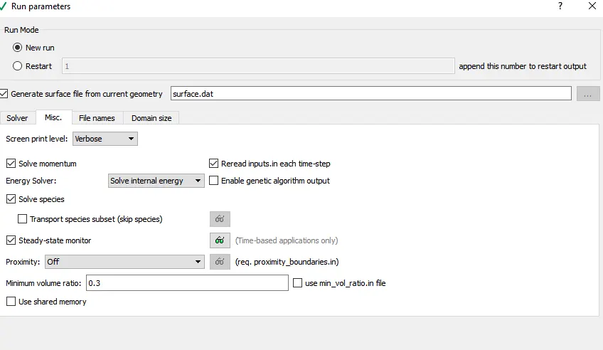
in run parameters - two main thinges to be considered
(a) select the flowing solver setting
RUN PARAMETERS:-
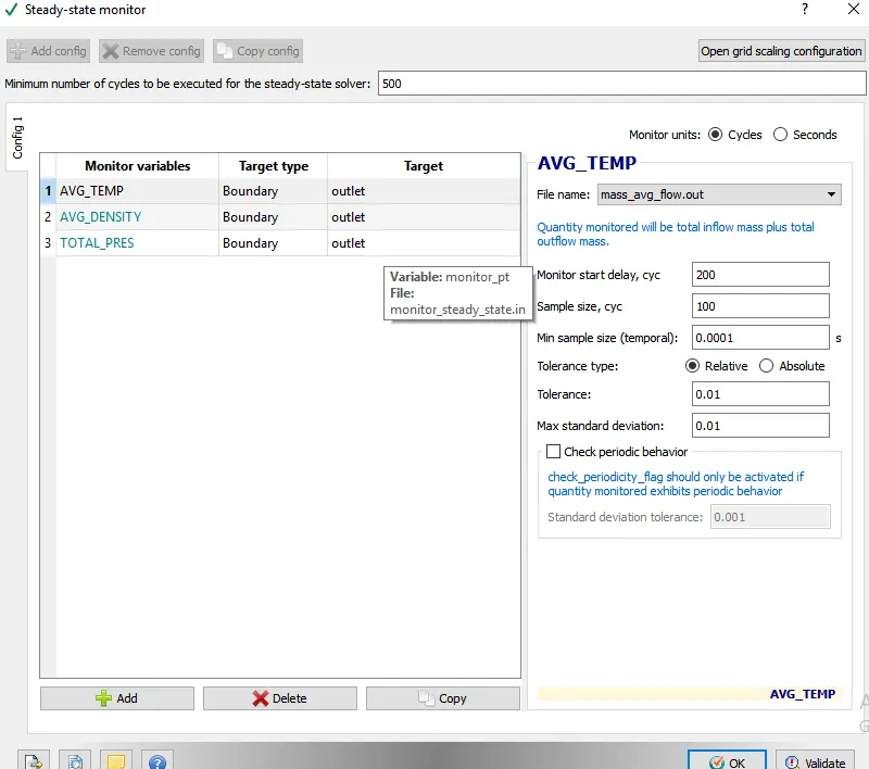
steady-state moniter:-
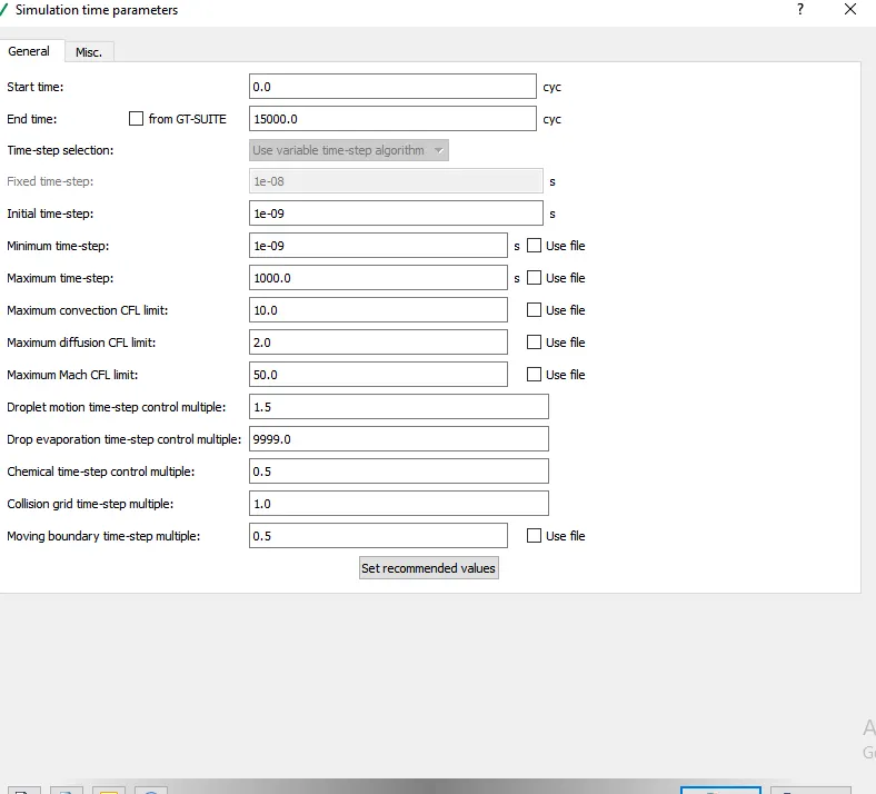
simulation parametes:-
solver parameters {steady-state}:-
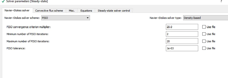
solver parameters {steady-state}:-
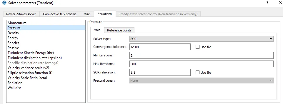
solver parameters{steady-state}:-
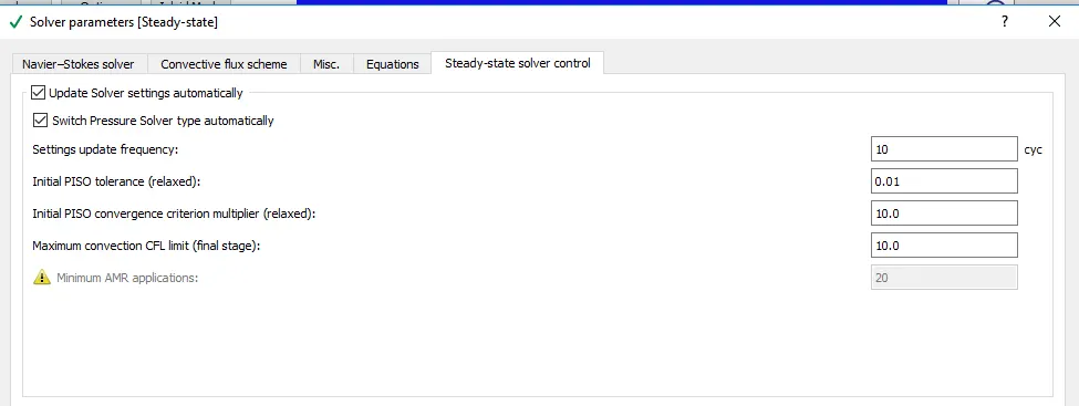
BOUNDARY CONDITION :-
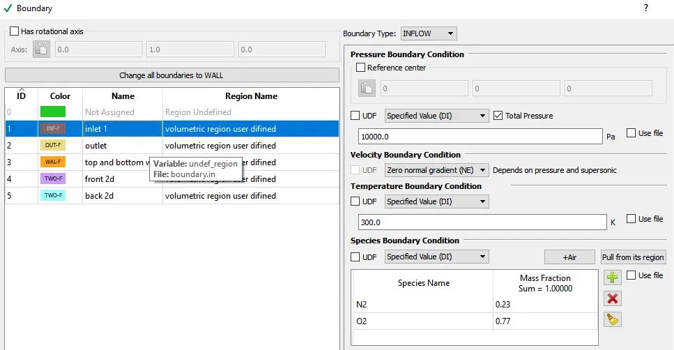
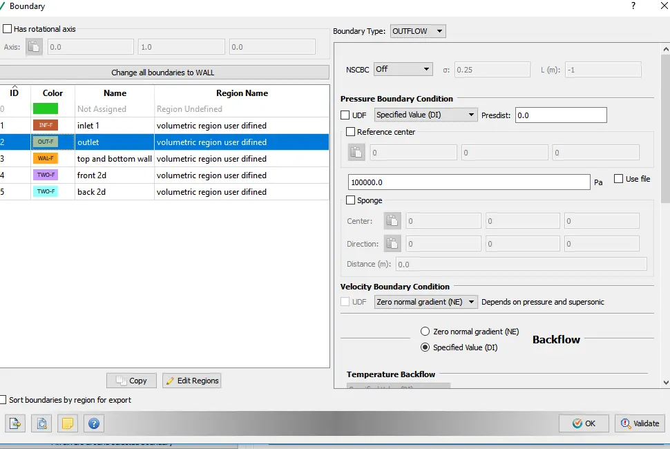
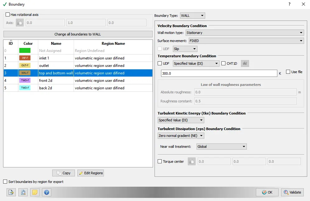
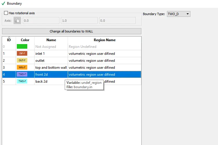
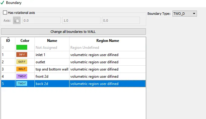
for front2D and back 2D boundary type is two _D
Regions and initialization:-
PHYSICAL MODEL:- Uncheck turbulence modeling in this case
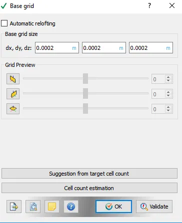
GRID CONTROL
post variable selection:-
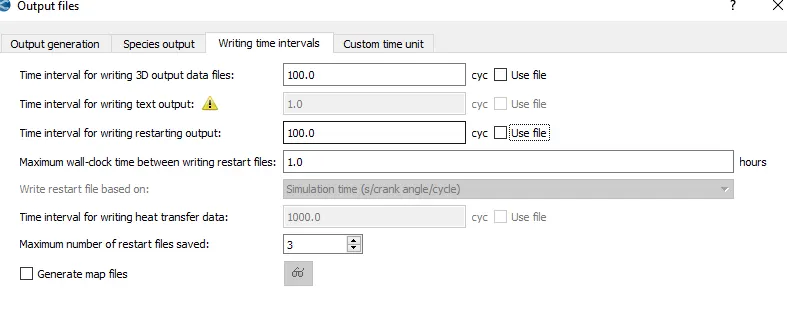
output files:-
In order to execute the simulation the directory in which these input files were stored was accessed in cygwin and the following command was typed "mpiexec.exe -n 4 converge.exe"
after the simulation was executed the results were converted into a from which would be compatible with paraview this was done using the post_convert.exe command
Results after post processing:-
{1} case no.1 (dx=dy=dz=2e-4m)
view of the mesh:-
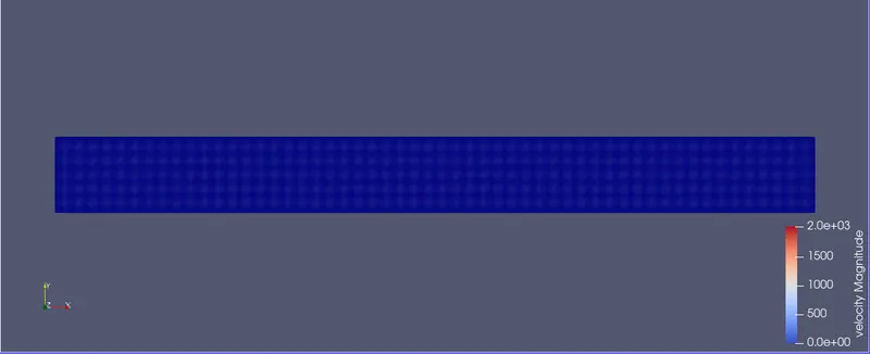

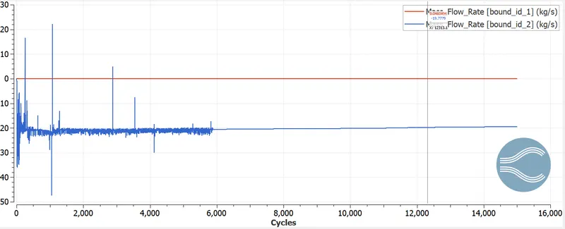
. mass flow rate plots :-
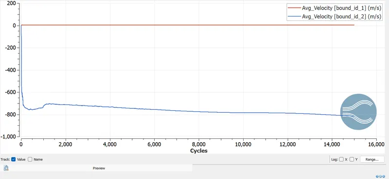
. velocity plots:-
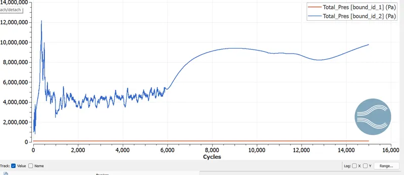
. pressure plots:-
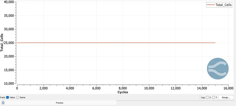
. Total cell counts plots:-
pressure coutour :-
velocity coutour:-
Results after post processing:-
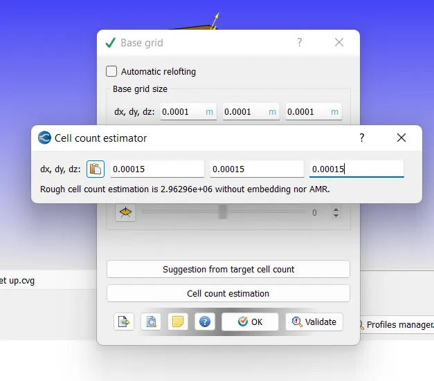
case no.2 (dx=dy=dz=1.5e-4m)
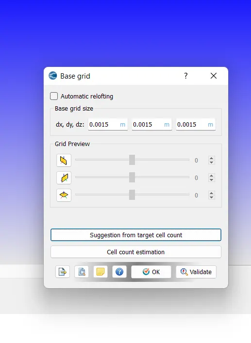
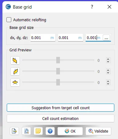
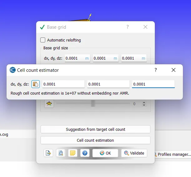
NOTE:-(i get this particular value from support engineer) in this cases we reduses mesh size because (cell count estimation more then 10L)
view of the mesh:-
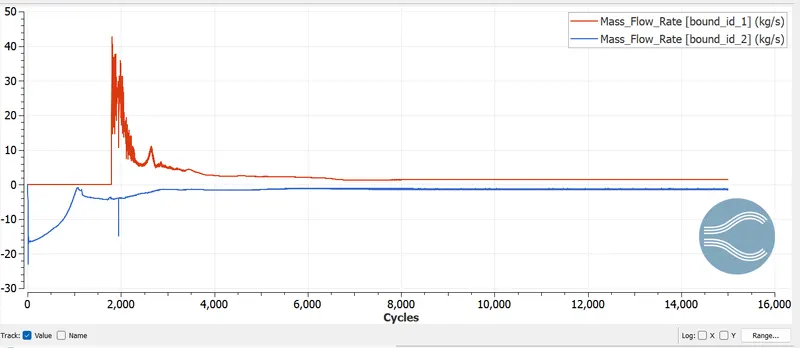
mass flow rate plots :-
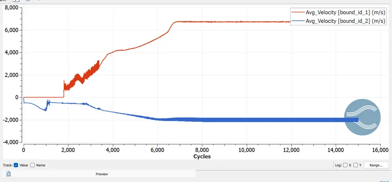
velocity plots:-
pressure plots:-
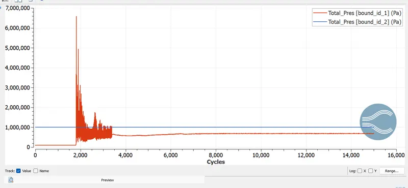
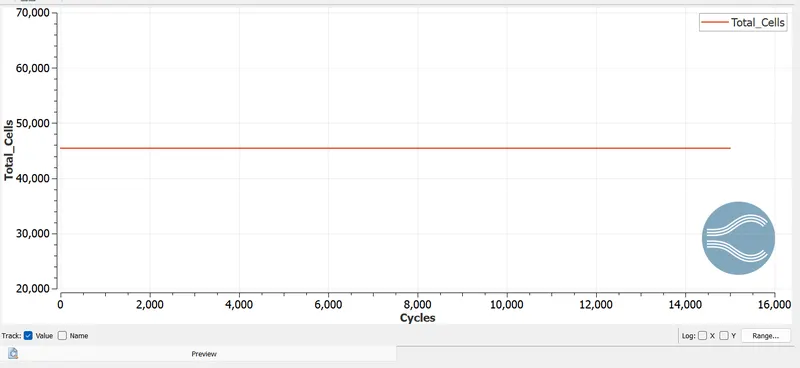
Total cell counts plots:-
pressure coutour :-
velocity coutour:-
Results after post processing:-
case no.3 (dx=dy=dz=1.0e-4m)
NOTE:-(i get this particular value from support engineer) in this cases we reduses mesh size because (cell count estimation more then 10L)
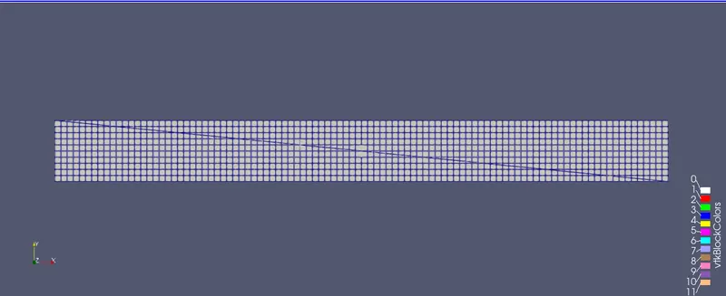
view of the mesh:-
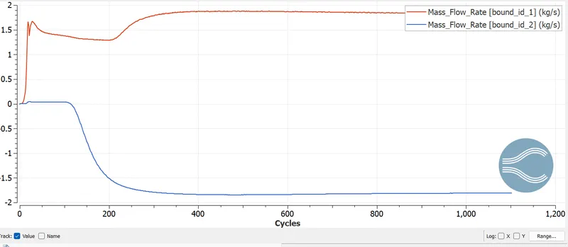
mass flow rate plots :-
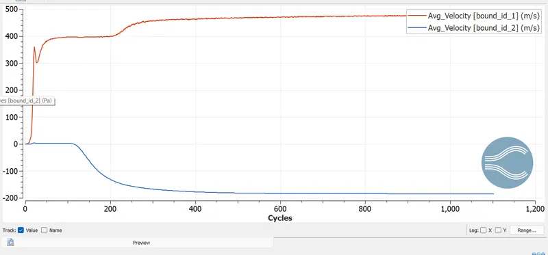
velocity plots:-
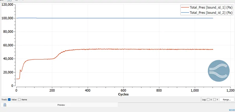
pressure plots:-
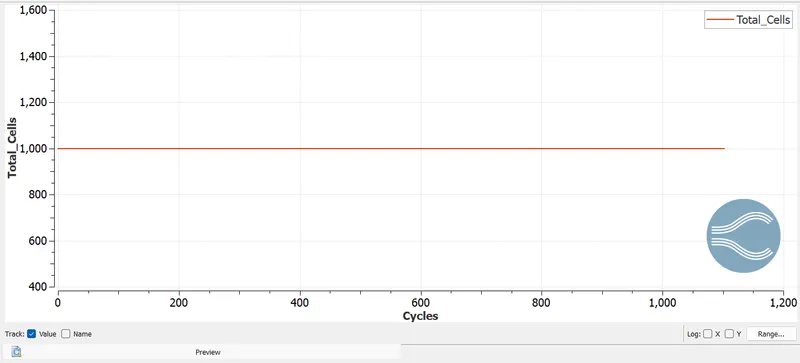
Total cell counts plots:-
pressure coutour :-
velocity coutours:-
IV.OBSERVATION:-
- From the simulation performed it is clear that for the mesh size (2e-4m,1.5e-4m, 1.0e-4m) the total cell countfor each of the mesh is 25000,45000,1000 respectively
- Hence as the mesh become finer the total cell count increses ,as the cell count increases the computinal time lso increses
- it is observerd that velocity in the initial case is highest but as the mesh is coare it is generally not preferred to be accurate in nest two cases it is calulated more accurately.
- the mass flow rate at the outlet for the refined cases is almost the same when both inlets and outlets are compared we can observe a positive and a negative flow
- as the mesh become finer the velocity profile obtained is also much clear compared to the other 2 cases
- hence as the size increases the results obtained are much clear and accurate
V.CONCLUSION :-
The channel flow simulation using converge CFD is performed with 3 different mesh sizes , accurate results are obtained.