Week 8 - Simulation of a backward facing step in OpenFOAM
Aim: To simulate the backward facing step in OpenFOAM.
Objectives:
- To simulate an incompressible-laminar-viscous flow through a backward facing step.
- Create Geometry and Mesh according to the given specifications for the simulation.
- Define the appropriate boundary conditions in the Geometry.
- To simulate the same set-up with different grading in the mesh and study the results obtained.
Choosing the solver:
We are going to simulate the backward facing step in a transient state. Our flow is to be an incompressible-laminar-viscous flow. Hence we might as well choose the icoFoam solver for the simulation. The icoFoam solver uses an algorithm called the Pressure Implicit with Splitting of Operators (PISO) algorithm to solve for the continuity equation. The continuity equation is as follows:
`∇⋅u=0`
and the momentum equation is as follows:
`∂/(∂t)(u)+∇⋅(u⊗u)−∇⋅(ν∇u)=−∇p`
where,
u = velocity in (m/s)
p = kinematic pressure in (m2/s2)
This particular solver can be found in the following directory path in the OpenFOAM tutorials:
openfoam8/tutorials/incompressible/icoFoam
Within icoFoam, we choose the "cavity" tutorial file and move a copy of this to the run folder in OpenFOAM.
File setup in the run folder:
After copying the "cavity" folder in the run folder, we can see the following files in the cavity folder:
- 0
- constant
- system
In the 0 folder, we are supposed to give the initial conditions for the velocity and pressure.
The initial conditions are set-up as follows:
For Velocity:
/--------------------------------- C++ -----------------------------------\
  =========                 |
  \\      /  F ield         | OpenFOAM: The Open Source CFD Toolbox
   \\    /   O peration     | Website:  https://openfoam.org
    \\  /    A nd           | Version:  8
     \\/     M anipulation  |
\---------------------------------------------------------------------------/
FoamFile
{
    version     2.0;
    format      ascii;
    class       volVectorField;
    object      U;
}
// * * * * * * * * * * * * * * * * * * * * * * * * * * * * * * * * * * * * * //

dimensions      [0 1 -1 0 0 0 0];

internalField   uniform (0 0 0);

boundaryField
{
    inlet
    {
        type            fixedValue;
        value           uniform (50 0 0);
    }

    outlet
    {
        type            zeroGradient;
    }

    frontAndBack
    {
        type            empty;
    }
    NoSlipWalls
    {
    	type		noSlip;
    }
}

// ************************* //
For Pressure:
/--------------------------------- C++ -----------------------------------\
  =========                 |
  \\      /  F ield         | OpenFOAM: The Open Source CFD Toolbox
   \\    /   O peration     | Website:  https://openfoam.org
    \\  /    A nd           | Version:  8
     \\/     M anipulation  |
\---------------------------------------------------------------------------/
FoamFile
{
    version     2.0;
    format      ascii;
    class       volScalarField;
    object      p;
}
// * * * * * * * * * * * * * * * * * * * * * * * * * * * * * * * * * * * * * //

dimensions      [0 2 -2 0 0 0 0];

internalField   uniform 0;

boundaryField
{
    inlet
    {
        type            zeroGradient;
    }

    outlet
    {
        type            fixedValue;
        value		 uniform 0;
    }

    frontAndBack
    {
        type            empty;
    }
    NoSlipWalls
    {
    	type		zeroGradient;
    }
}

// ************************* //
Within each of these files, we can see the dimensions section that is an array of seven numbers. These are essentially the dimensional numbers of the seven fundamental physical quantities in their SI units. The seven quantities are: [kg m s K mol A cd]
And since the unit for velocity is (m/s): we have [0 1 -1 0 0 0 0]
and since the unit for kinematic pressure is (m2/s2): we have [0 2 -2 0 0 0 0]
Now, we have to navigate to the system file within the cavity folder copied into the run folder.
Here, we can see the following set of text files:
- blockMeshDict
- controlDict
- fvSchemes
- fvSolution
We are not modifying anything in the fvSchemes and the fvSolution text files. However, we need to edit the blockMeshDict and the ControlDict to define our Geometry and Mesh with blockMeshDict and the boundary conditions in the controlDict.
The following Geometry is to be considered to understand our profile:
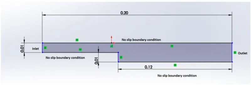
The profile is broken down into 5 blocks and the vertices and faces are defined appropriately:

Some of the important points to keep in mind while defining the geometry are as follows:
- It is important to keep track of the vertices defined, as they will be recognized as the point numbers while defining the blocks and faces.
- While creating blocks, we are supposed to give in 8 points. The 1st point is the local origin, the direction from point 1 to point 2 gives the local x-coordinate, the direction from point 2 to point 3 is the local y-coordinate and the perpendicular plane connecting 1st, 2nd and 3rd point give the local z-coordinate. And the rest of the 4 points are defined the same way for the opposite face of the block.
- While defining the faces for defining the boundary faces, the they follow the right-handed thumb rule.
The blockMeshDict file is edited as follows for the simple grading mesh:
/--------------------------------- C++ -----------------------------------\
  =========                 |
  \\      /  F ield         | OpenFOAM: The Open Source CFD Toolbox
   \\    /   O peration     | Website:  https://openfoam.org
    \\  /    A nd           | Version:  8
     \\/     M anipulation  |
\---------------------------------------------------------------------------/
FoamFile
{
    version     2.0;
    format      ascii;
    class       dictionary;
    object      blockMeshDict;
}
// * * * * * * * * * * * * * * * * * * * * * * * * * * * * * * * * * * * * * //

convertToMeters 0.1;

vertices
(
    (0 0 0)
    (8 0 0)
    (8 0.5 0)
    (0 0.5 0)
    (8 1 0)
    (0 1 0)
    (20 1 0)
    (20 0.5 0)
    (20 0 0)
    (20 -1 0)
    (8 -1 0)
    (0 0 0.5)
    (8 0 0.5)
    (8 0.5 0.5)
    (0 0.5 0.5)
    (8 1 0.5)
    (0 1 0.5)
    (20 1 0.5)
    (20 0.5 0.5)
    (20 0 0.5)
    (20 -1 0.5)
    (8 -1 0.5)

);

blocks
(
    hex (0 1 2 3 11 12 13 14) (80 5 1) simpleGrading (1 1 1)
    hex (3 2 4 5 14 13 15 16) (80 5 1) simpleGrading (1 1 1)
    hex (2 7 6 4 13 18 17 15) (120 5 1) simpleGrading (1 1 1)
    hex (1 8 7 2 12 19 18 13) (120 5 1) simpleGrading (1 1 1)
    hex (10 9 8 1 21 20 19 12) (120 10 1) simpleGrading (1 1 1)
);

edges
(
);

boundary
(
    inlet
    {
        type patch;
        faces
        (
            (0 11 14 3)
            (3 14 16 5)
        );
    }
    outlet
    {
        type patch;
        faces
        (
            (9 8 19 20)
            (8 7 18 19)
            (7 6 17 18)
        );
    }
    frontAndBack
    {
        type empty;
        faces
        (
            (0 3 2 1)
            (3 5 4 2)
            (10 1 8 9)
            (1 2 7 8)
            (2 4 6 7)
            (11 12 13 14)
            (14 13 15 16)
            (21 20 19 12)
            (12 19 18 13)
            (13 18 17 15)
        );
    }
    NoSlipWalls
    {
    	type walls;
    	faces
    	(
    		(5 16 15 4)
    		(4 15 17 6)
    		(0 1 12 11)
    		(10 21 12 1)
    		(10 9 20 21)
    	);
    }
);

mergePatchPairs
(
);

// ************************* //
The start-time, end-time and the time-steps are defined in the controlDict file as follows:
/--------------------------------- C++ -----------------------------------\
  =========                 |
  \\      /  F ield         | OpenFOAM: The Open Source CFD Toolbox
   \\    /   O peration     | Website:  https://openfoam.org
    \\  /    A nd           | Version:  8
     \\/     M anipulation  |
\---------------------------------------------------------------------------/
FoamFile
{
    version     2.0;
    format      ascii;
    class       dictionary;
    location    "system";
    object      controlDict;
}
// * * * * * * * * * * * * * * * * * * * * * * * * * * * * * * * * * * * * * //

application     icoFoam;

startFrom       startTime;

startTime       0;

stopAt          endTime;

endTime         0.2;

deltaT          0.0001;

writeControl    timeStep;

writeInterval   20;

purgeWrite      0;

writeFormat     ascii;

writePrecision  6;

writeCompression off;

timeFormat      general;

timePrecision   6;

runTimeModifiable true;


// ************************* //
Now that all the necessary files are edited properly, we have to navigate back to the cavity folder within the run folder. Type the command "blockMesh" to create the Mesh. If there are some errors while creating the mesh, it will be shown and we can rectify accordingly.
The generated mesh looks like the following:
Once the mesh is successfully created, we use the command "icoFoam" to run the solver.
Once, the solution has run successfully, we have to post-process the results and we use the "paraFoam" command to open ParaView to post-process the results.
The results are as follows:
The animation showing the velocity variation w.r.t time-steps shown in video whose link is as follows:
The variation of velocity at 0.085m from the inlet is shown in the following plot:
Changing the mesh grading:
The grading of the mesh is changed such that the mesh is denser at the boundary layers and also at the step region. the blockMeshDict file for the new mesh is as follows:
/--------------------------------- C++ -----------------------------------\
  =========                 |
  \\      /  F ield         | OpenFOAM: The Open Source CFD Toolbox
   \\    /   O peration     | Website:  https://openfoam.org
    \\  /    A nd           | Version:  8
     \\/     M anipulation  |
\---------------------------------------------------------------------------/
FoamFile
{
    version     2.0;
    format      ascii;
    class       dictionary;
    object      blockMeshDict;
}
// * * * * * * * * * * * * * * * * * * * * * * * * * * * * * * * * * * * * * //

convertToMeters 0.1;

vertices
(
    (0 0 0)
    (8 0 0)
    (8 0.5 0)
    (0 0.5 0)
    (8 1 0)
    (0 1 0)
    (20 1 0)
    (20 0.5 0)
    (20 0 0)
    (20 -1 0)
    (8 -1 0)
    (0 0 0.5)
    (8 0 0.5)
    (8 0.5 0.5)
    (0 0.5 0.5)
    (8 1 0.5)
    (0 1 0.5)
    (20 1 0.5)
    (20 0.5 0.5)
    (20 0 0.5)
    (20 -1 0.5)
    (8 -1 0.5)

);

blocks
(
    hex (0 1 2 3 11 12 13 14) (80 5 1) simpleGrading (1 0.2 1)
    hex (3 2 4 5 14 13 15 16) (80 5 1) simpleGrading (1 0.2 1)
    hex (2 7 6 4 13 18 17 15) (120 5 1) simpleGrading (1 0.2 1)
    hex (1 8 7 2 12 19 18 13) (120 5 1) simpleGrading (1 0.2 1)
    hex (10 9 8 1 21 20 19 12) (120 10 1) simpleGrading (1 0.2 1)
);

edges
(
);

boundary
(
    inlet
    {
        type patch;
        faces
        (
            (0 11 14 3)
            (3 14 16 5)
        );
    }
    outlet
    {
        type patch;
        faces
        (
            (9 8 19 20)
            (8 7 18 19)
            (7 6 17 18)
        );
    }
    frontAndBack
    {
        type empty;
        faces
        (
            (0 3 2 1)
            (3 5 4 2)
            (10 1 8 9)
            (1 2 7 8)
            (2 4 6 7)
            (11 12 13 14)
            (14 13 15 16)
            (21 20 19 12)
            (12 19 18 13)
            (13 18 17 15)
        );
    }
    NoSlipWalls
    {
    	type walls;
    	faces
    	(
    		(5 16 15 4)
    		(4 15 17 6)
    		(0 1 12 11)
    		(10 21 12 1)
    		(10 9 20 21)
    	);
    }
);

mergePatchPairs
(
);

// ************************* //
The mesh after the different grading factor looks as follows:
The solution is again run and the results are as follows:
The animation of the variation in velocity w.r.t time-step is shown in the youtube video whose link is as follows:
The plot for the variation in velocity near the step region at 0.085m from the inlet is as follows:
Observations on different grading factors:
- It can be seen in the animations that the coarser mesh at the bottom side of the graded (0.2) mesh has a thicker region with lower velocities. Generally, due to the no-slip condition at the boundary layer, the theoretical value of the velocity at the 1st layer of the boundary is zero and the velocity increases with at the further layers on top. Hence, the grading is to be made in such a way that all the boundary layers should have a finer mesh.
- The plots for the variation of velocity differ considerably. At this point, we don't have sufficient experimental values to compare and arrive at a conclusion on which one has more accuracy and is a better option in this particular case. However, we can come up with the general conclusion that the mesh needs to the finer at our area of interest to study.
This concludes the project to simulate the backward facing step in OpenFOAM.