Week 8 - Simulation of a backward facing step in OpenFOAM
AIM :
To carry out a transient simulation to simulate an incompressible-laminar-viscous flow through the backward facing step geometry.
OBJECTIVES :
- To perform a transient simulation to simulate an incompressible-laminar-viscous flow through the backward facing step geometry.
- Explain the entire simulation procedure (how you set up the case) and also provide explanations to every change you make inside the reference case files obtained from OpenFOAM tutorials.
- Perform 2 case studies as described below and compare the results.
Case 1 - Simulate the flow without using any grading factor (i.e., GF = 1)
Case 2 - Simulate the flow with grading factor of 0.2. The cells should be finer near the walls (including the step wall).
- Measure the velocity profile at 0.085 m from the inlet of the geometry for both case studies and compare.
- Explain why Grading/Growth factor is essential for meshing.
INTRODUCTION :
In this challenge, we are going to carry out a transient simulation to simulate an incompressible-laminar-viscous flow through the backward facing step geometry.
Transient flow :
Transient flow, is flow where the flow velocity and pressure are changing with time. When changes occur to a fluid systems such as the starting or stopping of a pump, closing or opening a valve, or changes in tank levels, then transient flow conditions exist, otherwise the system is steady state.
Transient flow is usually referred to as surge or water hammer.
Incompressible flow :
Incompressible flow (isochoric flow) refers to a flow in which the material density is constant within a fluid parcel - an infinitesimal volume that moves with the flow velocity.
Incompressible flow does not imply that the fluid itself is incompressible.
Example of incompressible fluid flow:
The stream of water flowing at high speed from a garden hose pipe which tends to spread like a fountain when held vertically up, but tends to narrow down when held vertically down. The reason being volume flow rate of fluid remains constant.
Laminar flow :
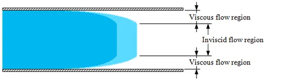
Laminar flow (sometimes called streamline flow) is a type of fluid (gas or liquid) flow in which the fluid travels smoothly or in regular paths with little or no mixing. In laminar flow, the velocity, pressure, and other flow properties at each point in the fluid remain constant.
Viscous flow :
Viscous Flow is the fluid flow in which the effects of viscosity are significant.
SPECIFICATIONS AND CONDITIONS :
The domain specifications for the backward facing step geometry is given by,
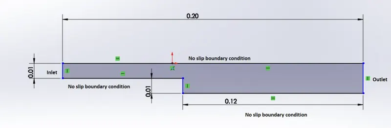
The solver can be chosen based on the described physics of the flow.
Mesh specification
- Number of cells along the x direction (longer dimension) = 200
- Number of cells along the longer y direction = 20;
We need to perform 2 case studies as described below and compare the results.
Case 1 - Simulate the flow without using any grading factor (i.e., GF = 1)
Case 2 - Simulate the flow with grading factor of 0.2. The cells should be finer near the walls (including the step wall).
SIMULATION PROCEDURE :
Problem Setup :
We first initialize the problem by navigating to the tutorials directory of OpenFOAM by using the “tut” command in the terminal window. From the tutorials, we have to figure out the suitable case file for our given problem, which is a incompressible-laminar-viscous flow. We use the “ls” command to list the contents (files or directories) present inside the directory.

As it is an incompressible flow, we navigate into the incompressible directory. We use the “cd” command to navigate and change the working directory using the terminal window.
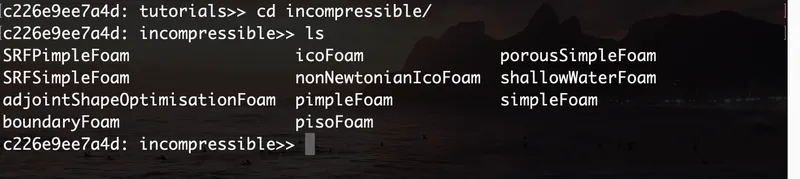
The next step involves navigating into the icoFoam directory. The icoFoam command solves the incompressible laminar Navier-Stokes equations. The code is inherently transient, requiring an initial condition (such as zero velocity) and boundary conditions.

Here, we use the cavity utility to create our required domain. We copy this directory into the $FOAM_RUN file, which is a default file OpenFOAM creates for us. We use the “cp -r” command to recursively create a copy of the contents of the file or directory into the $FOAM_RUN folder under the file name “Backward Facing Step”, for personal use. We create a copy of the files as OpenFOAM does not let us modify or make changes to its inbuilt tutorial files.

We then navigate to the copied tutorial file in the $FOAM_RUN directory to view the contents inside the folder.
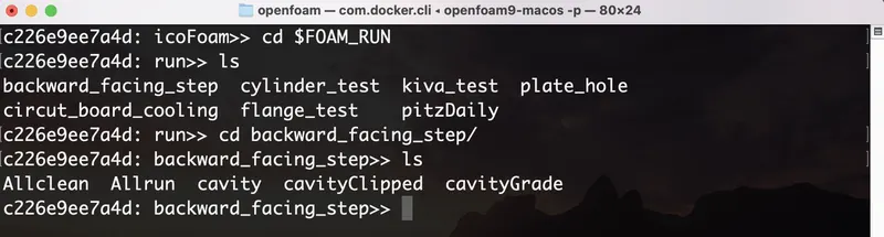
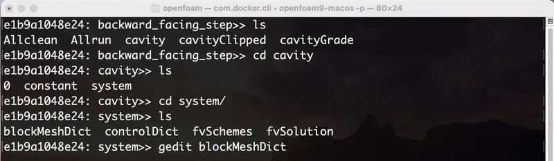
By navigating into the system file of the cavity folder, we can find 4 script files which we need to modify in order to obtain our respective domain and boundary conditions of the blockmesh. We modify the blockMeshDict file by using the “gedit” command, which is the default text editor.
CASE - 1 : NO GRADING FACTOR (GF = 1)
Geometry Definition :
Let us consider creating our required geometry using 5 blocks as shown in the figure below,
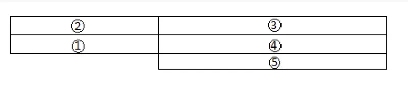
To input the dimensions of these blocks into OpenFOAM, we are going to be defining vertices at each and every corner of each block and thereby obtaining the co-ordinate points of every block.
Thereby, indexing the vertices on the back and front ends of the blocks, we get
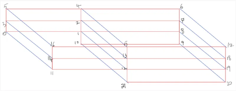
With reference to these vertices, we are going to be making certain modifications in the source codes so as to meet our specifications. They are as follows.
blockMeshDict file :
By navigating into the system directory of our copied “cavity test” file, we are going to find 4 files as shown below. We are going to use the “gedit” function, which is the default text editor, to make the required changes to our blockMeshDict file.

- Defining the Vertices
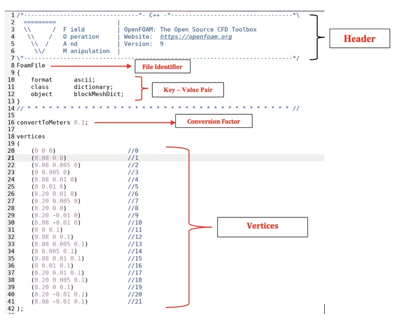
The blockMeshDict file contains the following parts,
i.) The first 7 lines of the file is called the Header, which are commands and are non-executable.
ii.) The next part of the file (lines 8 – 14) is referred to as the file identifier. The FoamFile line represents the software corresponding to the file is OpenFOAM. The structure of this part is referred to as a dictionary and it contains key-value pairs.
iii.) The next part of the file are the defined vertices of the blocks, which are the respective co-ordinates which we specify in an order obeying the right hand thumb rule.
- Mesh Generation
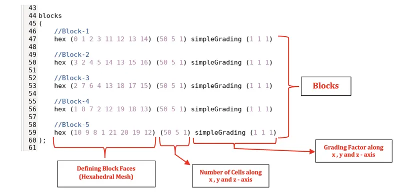
To create our required geometry mesh, we use a hexahedral mesh to define the faces of blocks. Similarly, we also define the number of cells present along the x, y and z – axes respectively as well.
As the case suggests, we provide a grading value of 1, to obtain equally spaced cells along all the three axes.
- Boundaries
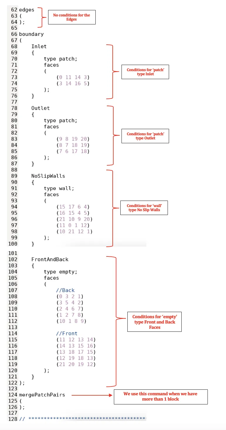
In the final step of the blockMeshDict file, we define the conditions of the inlet and outlet faces, which are of type “patch”. The patch is a basic type for a condition that contains no geometric or topological information about the mesh (with the exception of wall), e.g. an inlet or an outlet.
Similarly, we define the conditions for the no slip walls, which are of the type “wall”. A wall type is used instances where a patch that coincides with a wall needs to be identifiable as such, particularly where specialist modelling is applied at wall boundaries.
And finally, we define the conditions for the front and back faces which are of the type “empty”. While OpenFOAM always generates geometries in 3 dimensions, it can be instructed to solve in 2 dimensions by specifying a special empty condition on each patch whose plane is normal to the 3rd dimension for which no solution is required.
We do not provide any particular conditions for the edges of the geometry and hence, it is left blank.
controlDict file :
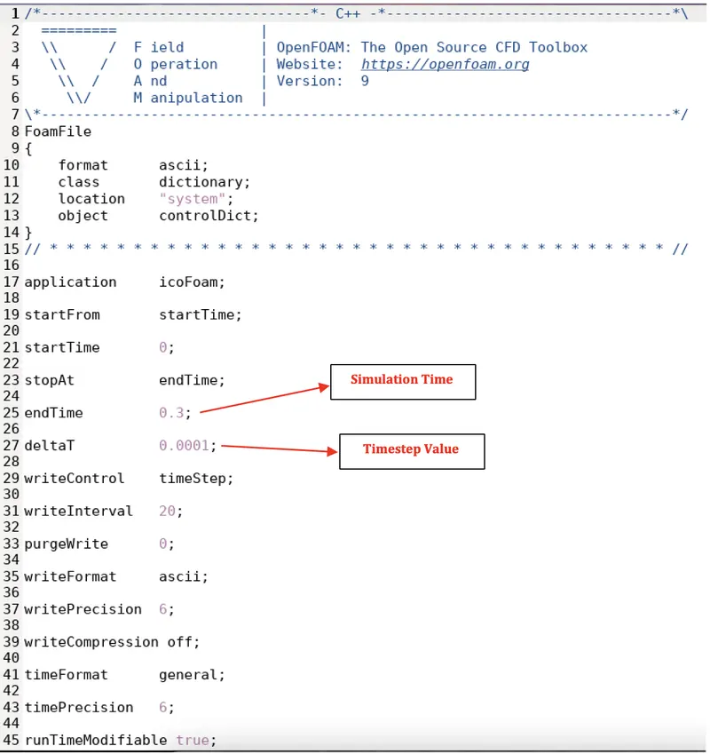
After finishing the modifications to the blockMeshDict file, we move on further to make the necessary changes to our controlDict file. In this file, we define the time interval for which our simulation is supposed to run (simulation time) and also the timestep value for the same, as shown below.
We do not make any further changes to the “fvSchemes” and “fvSolution” files in our system folder.
Initial Conditions :
We navigate into the initial value folder (0) of the cavity test file to modify the initial values for velocity (U) and pressure (p) respectively.
- Initial Velocity (U)
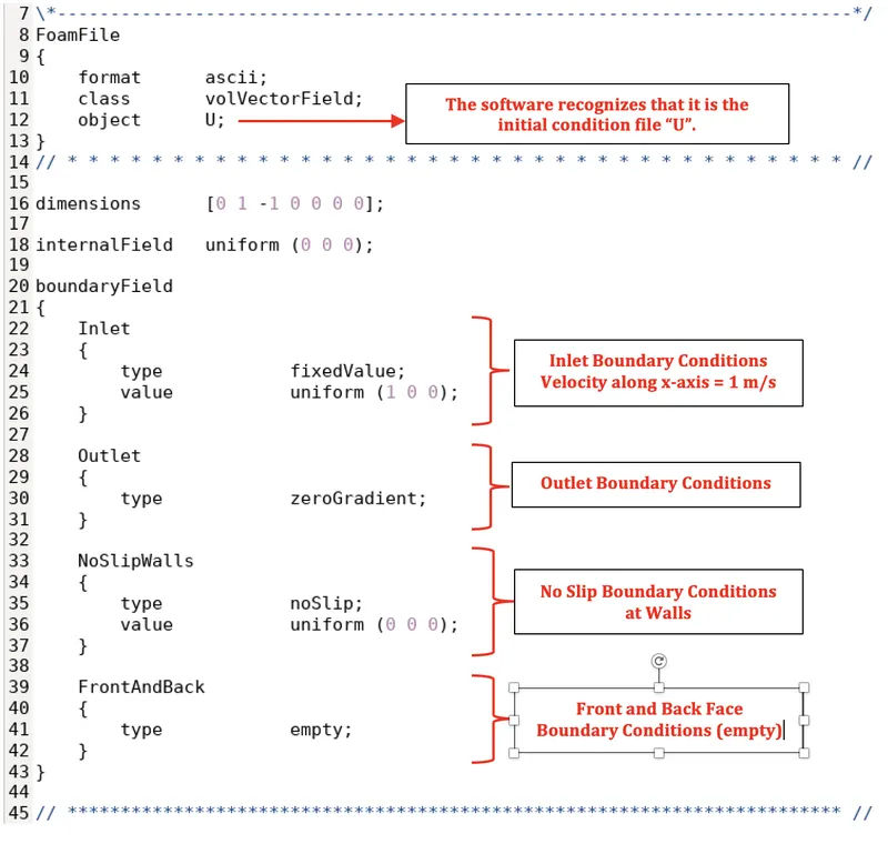
We specify the initial velocity conditions as shown below. The initial velocity along x-axis at the inlet is taken as 1 m/s and that at the outlet is allowed to float.
- Initial Pressure (p)
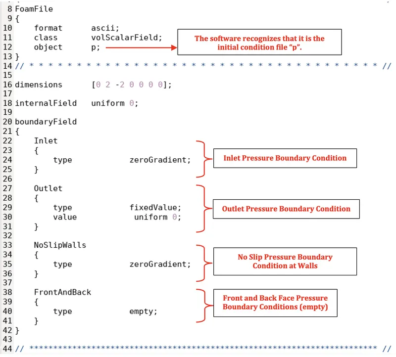
After completion of all the above mentioned steps, we then use the “blockMesh” command to create a mesh model of our geometry, with the number of cells along x and y – axes as previously specified above.
After creation of the meshed model, we finally use the “icoFoam” command to run the simulation for the same to obtain our final results.
Final Output Results :
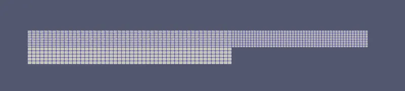
- Mesh Model
The meshed model of our respective geometry is obtained as shown below.
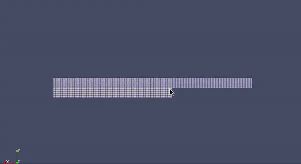
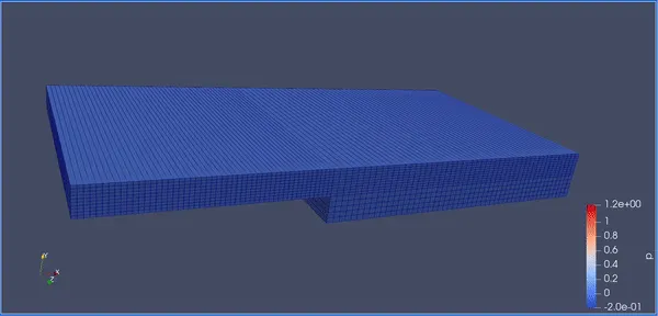
`360^o` view of meshed model :
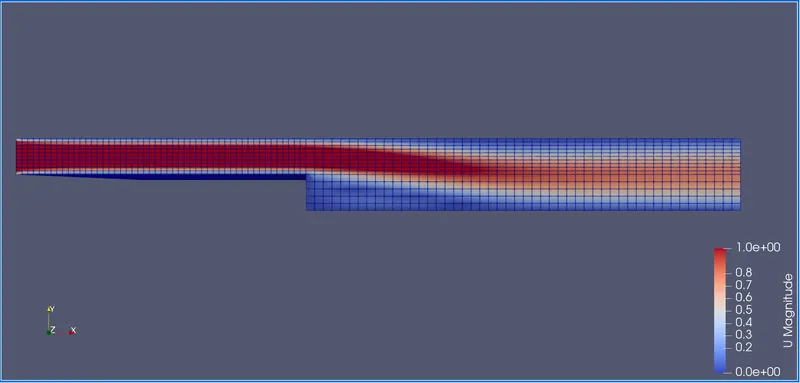
- Velocity Distribution
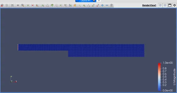
The velocity distribution across the geometry is shown in the below image and video as follows.
Video :
- Pressure Distribution
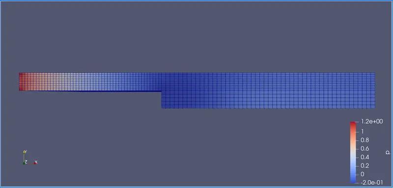
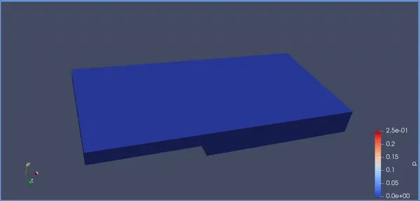
The pressure distribution across the geometry is shown as.
Video :
CASE – 2 : GRADING FACTOR OF 0.2
Here, we are going to simulate the problem for a grading factor of 0.2. That is, the cells are finer near the walls (including the step wall).
blockMeshDict file :
/*--------------------------------*- C++ -*----------------------------------*\
  =========                 |
  \\      /  F ield         | OpenFOAM: The Open Source CFD Toolbox
   \\    /   O peration     | Website:  https://openfoam.org
    \\  /    A nd           | Version:  9
     \\/     M anipulation  |
\*---------------------------------------------------------------------------*/
FoamFile
{
    format      ascii;
    class       dictionary;
    object      blockMeshDict;
}
// * * * * * * * * * * * * * * * * * * * * * * * * * * * * * * * * * * * * * //

convertToMeters 0.1;

vertices
(
    (0 0 0)                    //0
    (0.08 0 0)                 //1
    (0.08 0.005 0)             //2
    (0 0.005 0)                //3
    (0.08 0.01 0)              //4
    (0 0.01 0)                 //5
    (0.20 0.01 0)              //6
    (0.20 0.005 0)             //7
    (0.20 0 0)                 //8
    (0.20 -0.01 0)             //9
    (0.08 -0.01 0)             //10
    (0 0 0.1)                  //11
    (0.08 0 0.1)               //12
    (0.08 0.005 0.1)           //13
    (0 0.005 0.1)              //14
    (0.08 0.01 0.1)            //15
    (0 0.01 0.1)               //16
    (0.20 0.01 0.1)            //17
    (0.20 0.005 0.1)           //18
    (0.20 0 0.1)               //19
    (0.20 -0.01 0.1)           //20
    (0.08 -0.01 0.1)           //21
);

blocks
(
    //Block-1
    hex (0 1 2 3 11 12 13 14) (80 5 1) simpleGrading (0.2 5 1)

    //Block-2
    hex (3 2 4 5 14 13 15 16) (80 5 1) simpleGrading (0.2 0.2 1)

    //Block-3
    hex (2 7 6 4 13 18 17 15) (80 5 1) simpleGrading (5 0.2 1)

    //Block-4
    hex (1 8 7 2 12 19 18 13) (80 5 1) simpleGrading (5 5 1)

    //Block-5
    hex (10 9 8 1 21 20 19 12) (80 5 1) simpleGrading (5 5 1)
);

edges
(
);

boundary
(
    Inlet
    {
        type patch;
        faces
        (
            (0 11 14 3)
            (3 14 16 5)
        );
    }

    Outlet
    {
        type patch;
        faces
        (
            (9 8 19 20)
            (8 7 18 19)
            (7 6 17 18)
        );
    }

    NoSlipWalls
    {
        type wall;
        faces
        (
            (15 17 6 4)
            (16 15 4 5)
            (21 10 9 20)
            (11 0 1 12)
            (10 21 12 1)
        );
    }

    FrontAndBack
    {
        type empty;
        faces
        (
            //Back
            (0 3 2 1)
            (3 5 4 2)
            (2 4 6 7)
            (1 2 7 8)
            (10 1 8 9)

            //Front
            (11 12 13 14)
            (14 13 15 16)
            (13 18 17 15)
            (12 19 18 13)
            (21 20 19 12)
        );
    }
);

mergePatchPairs
(
);

// ************************************************************************* //
controlDict file :
/*--------------------------------*- C++ -*----------------------------------*\
  =========                 |
  \\      /  F ield         | OpenFOAM: The Open Source CFD Toolbox
   \\    /   O peration     | Website:  https://openfoam.org
    \\  /    A nd           | Version:  9
     \\/     M anipulation  |
\*---------------------------------------------------------------------------*/
FoamFile
{
    format      ascii;
    class       dictionary;
    location    "system";
    object      controlDict;
}
// * * * * * * * * * * * * * * * * * * * * * * * * * * * * * * * * * * * * * //

application     icoFoam;

startFrom       startTime;

startTime       0;

stopAt          endTime;

endTime         0.3;

deltaT          0.0001;

writeControl    timeStep;

writeInterval   200;

purgeWrite      0;

writeFormat     ascii;

writePrecision  6;

writeCompression off;

timeFormat      general;

timePrecision   6;

runTimeModifiable true;


// ************************************************************************* //
Initial Velocity file (U) :
/*--------------------------------*- C++ -*----------------------------------*\
  =========                 |
  \\      /  F ield         | OpenFOAM: The Open Source CFD Toolbox
   \\    /   O peration     | Website:  https://openfoam.org
    \\  /    A nd           | Version:  9
     \\/     M anipulation  |
\*---------------------------------------------------------------------------*/
FoamFile
{
    format      ascii;
    class       volVectorField;
    object      U;
}
// * * * * * * * * * * * * * * * * * * * * * * * * * * * * * * * * * * * * * //

dimensions      [0 1 -1 0 0 0 0];

internalField   uniform (0.1 0 0);

boundaryField
{
    Inlet
    {
        type            fixedValue;
        value           uniform (0.2 0 0);
    }

    Outlet
    {
        type            zeroGradient;
    }

    NoSlipWalls
    {
        type            noSlip;
    }

    FrontAndBack
    {
        type            empty;
    }
}

// ************************************************************************* //
Initial Pressure file (p) :
/*--------------------------------*- C++ -*----------------------------------*\
  =========                 |
  \\      /  F ield         | OpenFOAM: The Open Source CFD Toolbox
   \\    /   O peration     | Website:  https://openfoam.org
    \\  /    A nd           | Version:  9
     \\/     M anipulation  |
\*---------------------------------------------------------------------------*/
FoamFile
{
    format      ascii;
    class       volScalarField;
    object      p;
}
// * * * * * * * * * * * * * * * * * * * * * * * * * * * * * * * * * * * * * //

dimensions      [0 2 -2 0 0 0 0];

internalField   uniform 0;

boundaryField
{
    Inlet
    {
        type            zeroGradient;
    }

    Outlet
    {
        type            fixedValue;
        value            uniform 0;
    }

    NoSlipWalls
    {
        type            zeroGradient;
    }

    FrontAndBack
    {
        type            empty;
    }
}

// ************************************************************************* //
Results (GF = 0.2) :
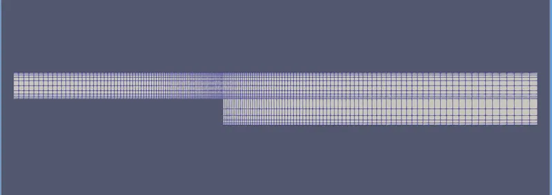
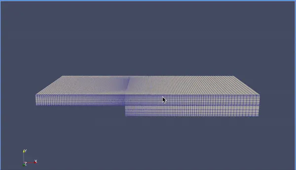
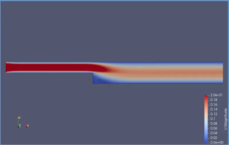
By running the simulation by making the respective modifications to the grading factors of the hexahedral meshes as shown above, we obtain a mesh model with fine meshing around the walls. Thereby, we obtain the following results.
- Mesh Model
The meshed model of our respective geometry is obtained as shown below.
`360^o` view of meshed model :
- Velocity Distribution
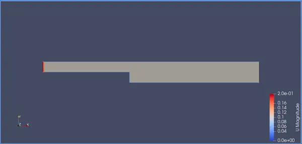
The velocity distribution across the geometry is shown in the below image and video as follows.
Video :
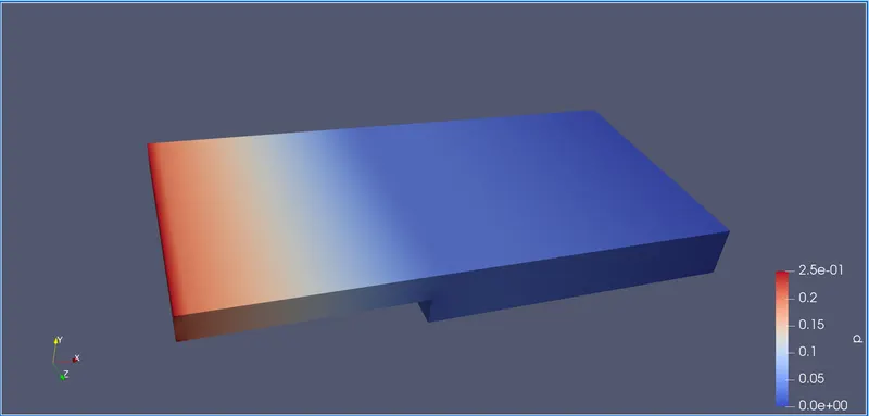
- Pressure Distribution
The pressure distribution across the geometry is shown as.
Video :
Why is grading / growth factor essential for meshing ?
Mesh Grading basically refers to a technique called mesh stretching, which helps us to stretch the mesh along any particular direction (x , y or z direction). This helps us in increasing the computational efficiency of the simulations.
`"Mesh Grade" = "Size of End Cell" / "Size of Starting Cell"`
The goal of meshing in CFD is to obtain the best mesh possible without sacrificing reasonable accuracy. A finer mesh at the areas where the fluid shows large changes, leads to higher accuracy. Thereby, we use a finer mesh around the walls of the geometry and also around the point where we expect our results.
Coarse and Fine Mesh :
A coarse mesh is the one where mesh elements are kept bigger such that they accommodate the geometry with less number of total mesh elements. Coarse mesh is generally what the CFD/FEA simulation is initially run with and then the mesh is refined further until we reach the point of validation where the results are no longer mesh dependent.
A refined mesh is basically a finer mesh with smaller elements. When the geometry has features like sharp angles, edges, etc. a relatively finer mesh is required to capture them.
CONCLUSION :
The transient simulation of an incompressible-laminar-viscous flow through the backward facing step geometry has been carried for both the cases where GF = 1 and another of GF = 0.2, respectively and the results have been obtained.
The entire simulation procedure has been clearly explained along with the significance of the grading / growth factor and how it affects the flow properties.
From the above case studies, we can observe that a finer mesh around the regions where large motion of the fluid occurs, leads to much accurate results when compared to that of a normal or coarse mesh region. Thereby, we can conclude that using a fine mesh around the regions or the walls where there is higher fluid interaction, leads to more accurate results wherein we can more clearly capture these changes more accurately.