Week 2- 2R Robotic Arm Challenge
Objectives :
- Write a Matlab program to simulate the forward kinematics of a 2R Robotic Arm.
- Create an animation file of the plot.
Introduction :
A robotic arm, which can also be referred to as a ‘mechanical arm’ is a device that operates in a similar way as to a human arm. It consists of a number of joints that can either move along an axis or which can rotate in various directions. The robotic arm’s job is to move an end effector from one point to another.
And also, kinematics refers to the study of motion of a system of bodies without considering the forces acting on the body. Thereby, the foremost objective of this problem is to calculate the workspace or reach of the robotic arm.
In this case, we are considering a simple robotic arm with two links and two rotational joints.
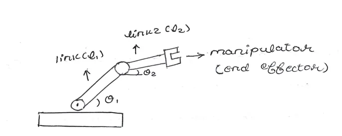
The above diagram represents a robotic arm fixed to a base, with two links ( l1 and l2 ) and a manipulator or end effector attached to its end.
Link 1 makes an angle of ‘θ1’ with respect to x-axis and link 2 makes an angle ‘θ2’.
Co-ordinates of points :
Let us consider the co-ordinates of the origin point of link-1 as ( x0 , y0 )
x0 = 0 and y0 = 0
Considering the final point of link-1, which makes an angle ‘θ1’ with the base and is also the origin point of link-2, as ( x1 , y1 )
x1 = l1 * cos θ1 and y1 = l1 * sin θ1
Considering the final point of link-2, which makes an angle ‘θ2’ with the x-axis and has the manipulator fixed to it, as ( x2 , y2 )
x2 = x1 + l2 * cos θ2 and y2 = y1 + l2 * sin θ2
Program :
% Forward Kinematics of 2R Robotic Arm
clear all
close all
clc

% inputs
% length of links
l1 = 2;
l2 = 1.5;

% angle made by links wrt x-axis
theta1 = linspace(0,90,20);
theta2 = linspace(0,90,20);

ct = 1;
% for loop function
% first loop counter
for i = 1:length(theta1)
    THETA1 = theta1(i);

    % second loop counter
    for j = 1:length(theta2)
        THETA2 = theta2(j);

        % coordinates
        % origin of link-1
        x0 = 0;
        y0 = 0;

        % end of link-1 and origin of link-2
        x1 = l1 * cosd(THETA1);
        y1 = l1 * sind(THETA1);

        % end of link-2
        x2 = x1 + l2*cosd(THETA2);
        y2 = y1 + l2*sind(THETA2);

        % plotting
        plot([x0 x1],[y0 y1],[x1 x2],[y1 y2],'linewidth',4)
        axis([-0.2 4 0 4])
        pause(0.04)
        M(ct)=getframe(gcf);
        ct = ct+1;
    end
end

% video file
movie(M)
videofile = VideoWriter('forward_kinematics.avi','uncompressed AVI')
open(videofile)
writeVideo(videofile,M)
close(videofile)
who
Program explanation :
The above program represents the forward kinematics of a 2R-robotic arm.
Here we are considering the respective lengths of link-1 as 2m and link-2 as 1.5m. Also taking into consideration, the angles made by link-1 and link-2 with x-axis as theta1 and theta2, which is an array of 0 to 90 degrees with 20 equally distributed intervals.
Here, we are using a 'for loop' function to plot each and every possible movement and degree of rotation of both the links of the robotic arm. As each of the loops is processed, the position of the links is being plotted. By using the 'axis' function to fix the x and y-axes of the plot and using the 'pause' function of a certain interval, we obtain a figure portraying the workspace of the robotic arm.
Output video :
https://1drv.ms/u/s!AmtBfxdB-9wDiyllf2pFjzI2-Wb4
The above OneDrive link contains the output video of the plot. The respective movements of both the links are observed, and thereby representing the entire workspace of the arm.
Problems faced :
- While running the program, I encountered a small confusion in the ‘for loop’ stage as I had entered the same loop counter “ i ” for both the loops instead of “ j ” for the second for loop.
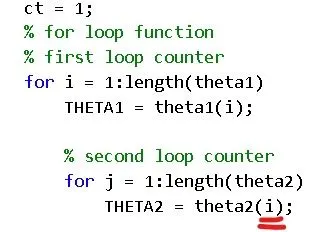
Result : Both links were moving together simultaneously without any induvidual rotation.
Reference link : https://1drv.ms/u/s!AmtBfxdB-9wDiyqxGiQ3Wv1byPPx
- Faced an error as i had entered ‘ cos ‘ and ‘ sin ‘ instead of ‘ cosd ‘ and ‘ sind ‘ in the co-ordinate variables. Error occurred as values were run in radians instead of degrees.
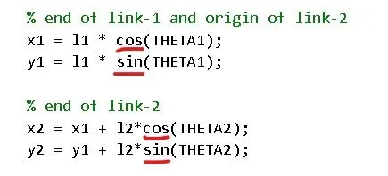
Result : Abnormal movement of the links in x and y direction.
Reference link : https://1drv.ms/u/s!AmtBfxdB-9wDiyyN52s6fRqzrJ2J
3. During the plotting stage :
- Getting confused in the proper entry of ‘x’ and ‘y’ co-ordinates in the plot function : leading to irregular plot.
- Not using the ‘axis’ function : movement of the x and y axes and plot is not fixed.
- Very less time interval of ‘pause’ function : the links move very fast.
Original :

Mistake :

where, the step ' b ' has been skipped.
Result : No intersection of the links, moving axes, plot not fixed and very fast abnormal rotation of links.
Reference link : https://1drv.ms/u/s!AmtBfxdB-9wDiy0zOL64GQL0Pza8