Simulation of a backward facing step geometry using OpenFOAM
Introduction
In this project, we will simulate an incompressible-laminar-viscous flow through a backward-facing step geometry using OpenFoam. OpenFoam is an open-source CFD software developed using the C++ programming language.
Terminology
Incompressible flow - A flow is said to be incompressible if the density at each point in the flow is constant, or in laymen's terms the flow cannot be compressed, no matter how much force or pressure is applied to it. Incompressibility plays a significant role in predicting the behavior of the fluid.
Laminar flow - A flow is said to be laminar when its Reynolds number is less than 2000 (might change as per situation), or in laymen's terms, it is a smooth flow, where there is no mixing of layers.
Reynolds number - It is the ratio of inertial force to the shear force of a fluid. It depends on the geometry and properties of the flow.
Viscous flow - A flow where there is resistance to motion between layers of fluid by the adjacent layers is called a viscous flow.
Solver
To know which solver is to be used to solve a particular problem, refer to references[1].
The solver used in this case is the icoFoam. icoFoam is a Transient solver for incompressible, laminar flow of Newtonian fluids. icoFoam uses PISO algorithm to solve the continuity and the momentum equations.
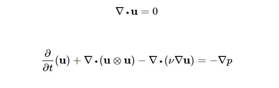
One can find the predefined value for viscosity, in the file, 'transportproperties', as 0.01. It is notable that one cannot find the predefined value for density anywhere in the solver. The reason I assume for this is (please correct me if I am wrong, in the comments section), that density is calculated within the solver to maintain the Reyniolds number within a limit, so that the flow is always laminar.
Geometry
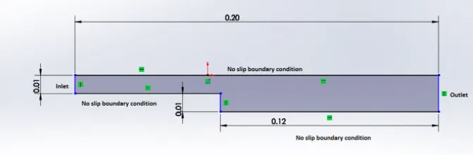
The units are chosen in such a way hat they maintain consistency with all other quantities like velocity, pressure etc. Further one can also change the dimensions while editing the blockMeshDict file.
Note - In the figure shown above, the No slip boundary condition has been missed for the step wall.
However defining geometry to OpenFoam is not as easy as it was shown above, to do this we have to edit the blockMeshDict file.
OpenFoam does not allow us to edit files in the tutorial (in-built) folder. So we have to copy the file and paste it in a location of our choice. It is prescribed to save it in $FOAM_RUN folder, as it can be easily executed from there.
Basic commands used in OpenFoam
cd : enter a folder
ls : display contents in the folder
cd .. : move onestep up in folder
cp : copy file
rm : delete file
-r : must be used while dealing with files (for eg - to copy a file ; use cp -r filename)
run : shortcut for $FOAM_RUN folder
tut : shortcut for Tutorials folder
paraFoam : Opens Praraview
Solvers can be used independently in FOAM_RUN folder by calling their names. (In this project icoFoam was used)
BlockMeshDict
/*--------------------------------*- C++ -*----------------------------------*
  =========                 |
  \      /  F ield         | OpenFOAM: The Open Source CFD Toolbox
   \    /   O peration     | Website:  https://openfoam.org
    \  /    A nd           | Version:  9
     \/     M anipulation  |
*---------------------------------------------------------------------------*/
FoamFile
{
    format      ascii;
    class       dictionary;
    object      blockMeshDict;
}
// * * * * * * * * * * * * * * * * * * * * * * * * * * * * * * * * * * * * * //

convertToMeters 1;

vertices
(
    (0 0 0)
    (0.08 0 0)
    (0.08 0.005 0)
    (0 0.005 0)
    (0.08 0.01 0)
    (0 0.01 0)
    (0.2 0.01 0)
    (0.2 0.005 0)
    (0.2 0 0)
    (0.2 -0.01 0)
    (0.08 -0.01 0)
    (0 0 0.1)
    (0.08 0 0.1)
    (0.08 0.005 0.1)
    (0 0.005 0.1)
    (0.08 0.01 0.1)
    (0 0.01 0.1)
    (0.2 0.01 0.1)
    (0.2 0.005 0.1)
    (0.2 0 0.1)
    (0.2 -0.01 0.1)
    (0.08 -0.01 0.1)
);

blocks
(
    hex (0 1 2 3 11 12 13 14) (80 5 1) simpleGrading (0.2 1 1)
    hex (3 2 4 5 14 13 15 16) (80 5 1) simpleGrading (0.2 1 1)
    hex (2 7 6 4 13 18 17 15) (120 5 1) simpleGrading (20 1 1)
    hex (1 8 7 2 12 19 18 13) (120 5 1) simpleGrading (20 1 1)
    hex (10 9 8 1 21 20 19 12) (120 10 1) simpleGrading (20 0.2 1)
);

edges
(
);

boundary
(
    inlet
    {
        type patch;
        faces
        (
           (0 11 14 3)
           (3 14 16 5)
        );
    }
    outlet
    {
        type patch;
        faces
        (
           (20 9 8 19)
           (19 8 7 18)
           (18 7 6 17)
        );
    }
    frontAndBack
    {
        type empty;
        faces
        (
           (0 3 2 1)
           (3 5 4 2)
           (10 1 8 9)
           (1 2 7 8)
           (2 4 6 7)
           (12 13 14 11)
           (13 15 16 14)
           (20 19 12 21)
           (19 18 13 12)
           (18 17 15 13)
        );
    }
    noslipWalls
    {
        type wall;
        faces
        (
           (15 4 5 16)
           (17 6 4 15)
           (11 0 1 12)
           (12 1 10 21)
           (10 9 20 21)
        );
    }


);

mergePatchPairs
(
);
Similarlly, we also have to edit the p and U files, which stand for Pressure and Velocity, so as to define them at the inlet/outlet as desired. These can be found in the folder '0'. Here 0 stands for timestep 0.
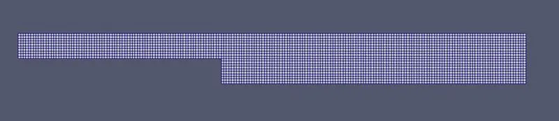
To verify the geometry defined, one can use the blockMesh command and then visualize it using the blockMesh command.

The mesh shown above is a graded/ non uniform mesh. Grading a mesh is important to get accurate results where there is a significant gradient in the flow properties, or where there is change in geometry. The level of grading required can be set by changing the values in SimpleGrading().
To get a uniform mesh, we simply have to replace all values in SimpleGrading to (1 1 1).
Pressure file
/*--------------------------------*- C++ -*----------------------------------*
  =========                 |
  \      /  F ield         | OpenFOAM: The Open Source CFD Toolbox
   \    /   O peration     | Website:  https://openfoam.org
    \  /    A nd           | Version:  9
     \/     M anipulation  |
*---------------------------------------------------------------------------*/
FoamFile
{
    format      ascii;
    class       volScalarField;
    object      p;
}
// * * * * * * * * * * * * * * * * * * * * * * * * * * * * * * * * * * * * * //

dimensions      [0 2 -2 0 0 0 0];

internalField   uniform 0;

boundaryField
{
    inlet
    {
        type            zeroGradient;
    }

    outlet
    {
        type            fixedValue;
        value		uniform 0
    }

    frontAndBack
    {
        type            empty;
    }

    noslipWalls
    {
    	type		zeroGradient;
    }
}

// ************************************************************************* //
Velocity file
/*--------------------------------*- C++ -*----------------------------------*
  =========                 |
  \      /  F ield         | OpenFOAM: The Open Source CFD Toolbox
   \    /   O peration     | Website:  https://openfoam.org
    \  /    A nd           | Version:  9
     \/     M anipulation  |
*---------------------------------------------------------------------------*/
FoamFile
{
    format      ascii;
    class       volVectorField;
    object      U;
}
// * * * * * * * * * * * * * * * * * * * * * * * * * * * * * * * * * * * * * //

dimensions      [0 1 -1 0 0 0 0];

internalField   uniform (0 0 0);

boundaryField
{
    inlet
    {
        type            fixedValue;
        value           uniform (1 0 0);
    }

    outlet
    {
        type            zeroGradient;
    }

    frontAndBack
    {
        type            empty;
    }

    noslipWalls
    {
    	type		noSlip;
    }
}

// ************************************************************************* //
One should be careful while editing these files, as one might provide the wrong conditions at the wrong location.
ControlDict
This file has to be edited to specify the start time, end time, time step.
Unlink Matlab, where all the values are stored, here we must specify at which time interval the values must be stored. A separate file is created to store values particularly at a specified time step.
/*--------------------------------*- C++ -*----------------------------------*
  =========                 |
  \      /  F ield         | OpenFOAM: The Open Source CFD Toolbox
   \    /   O peration     | Website:  https://openfoam.org
    \  /    A nd           | Version:  9
     \/     M anipulation  |
*---------------------------------------------------------------------------*/
FoamFile
{
    format      ascii;
    class       dictionary;
    location    "system";
    object      controlDict;
}
// * * * * * * * * * * * * * * * * * * * * * * * * * * * * * * * * * * * * * //

application     icoFoam;

startFrom       startTime;

startTime       0;

stopAt          endTime;

endTime         0.1;

deltaT          1e-5;

writeControl    timeStep;

writeInterval   20;

purgeWrite      0;

writeFormat     ascii;

writePrecision  6;

writeCompression off;

timeFormat      general;

timePrecision   6;

runTimeModifiable true;


// ************************************************************************* //
icoFoam is used to execute the files. After successful execution, we can see the folders named 0.1,0.2 (timesteps)(depending upon the interval specified in ControlDict file) in the folder, as shown below
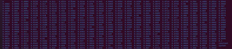
Here each folder has properties p and U at the timesteps (folder name).
We now use, paraFoam command, to open Paraview.
Results
1. Pressure at Timestep 1
a. Uniform grading

b.Grading 0.2

2. Pressure at timestep 500
a. Uniform grading
b. Grading 0.2

3. Velcoty at timestep 1
a. Uniform grading

b.Grading 0.2

4. Velocity at timestep 500
a. Uniform grading
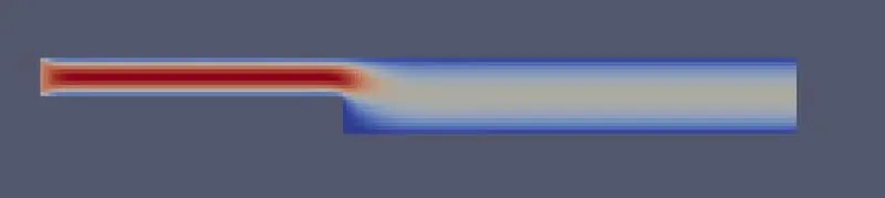
b.Grading 0.2

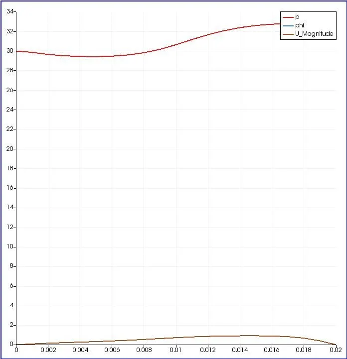
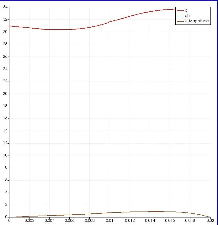
It is very easy to not find difference between results and initial cond for uniform mesh and graded mesh in the above simulations. But it can be seen in the plots below.
5. Plotting p & U at 0.85m from inlet at timestep 1
Uniform grading & grading 0.2
6. Plotting p & U at 0.85m from inlet at timestep 500
Uniform grading & grading 0.2
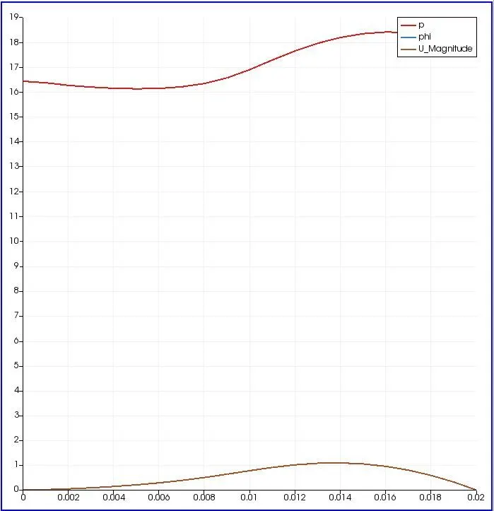
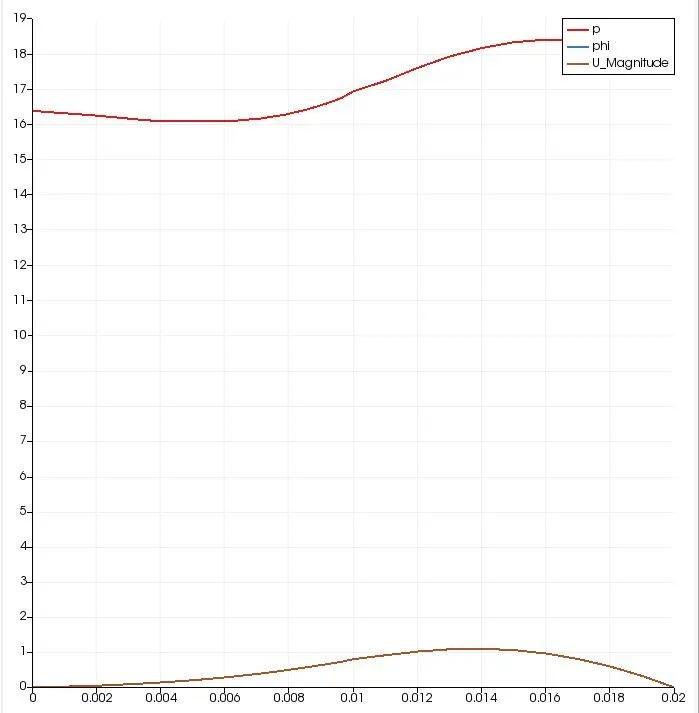
Not much significant difference is seen with the present grading. But some general takeaway's are that as the mesh becomes finer, the computation time and energy increases, it also increases the accuracy of the results.
Referencess -
1.https://www.openfoam.com/documentation/user-guide/a-reference/a.1-standard-solvers