Validation studies of Symmetry BC vs Wedge BC in OpenFOAM vs Analytical H.P equation
In this project, A laminar incompressible fluid flow through a cylindrical pipe is simulated using symmetry and wedge boundary conditions in OpenFoam and the results are validated with Analytical results obtained from MATLAB.
Hagen-Poiseullie's law
Hagen-Poiseullie's law governs the Laminar incompressible flow. It gives the pressure drop in a Laminar incompressible and Newtonian fluid flowing through a long cylindrical pipe of constant cross-section.
Assumptions
- Laminar flow - A flow is said to be laminar if the fluid layers run smoothly over each other and do not intermix. In mathematical terms, a flow whose Reynolds number is less than a specified value (which varies from situation to situation) is a Laminar flow.
To understand more about the flow behavior, I strongly recommend you to watch this video by "The Efficient Engineer". - Incompressible flow - A flow is said to be incompressible if it doesn't compress under pressure, in mathematical terms, its density remains constant throughout the flow.
- Newtonian fluid - A Newtonian fluid is a fluid in which the viscous stresses arising from the flow are, at every point linearly correlated to the local strain rate.
`tau alpha (delu)/(dely)`
`tau = mu(delu)/(dely)` - Dimensional Constraints - The length of the pipe should be substantially longer than its diameter.
`l/r<(Re)/48`
where,
l is the length of the pipe
r is the radius of the pipe, and
Re is the Reynolds number of the flow.
Mathematical Equation
`Deltap=(8mulQ)/(pir^4)`
where,
`Deltap` is the pressure drop across the pipe
`mu` is the dynamic viscosity
`l` is the length of the pipe
`Q` is the volumetric flow rate, and
`r` is the radius of the pipe.
The derivation to the above equation can be found in any standard Fluid dynamics textbook.
Applications
- Airflow in lung alveoli
- Flow-through a drinking straw
- Flow-through a hypodermic needle
Introduction to Darcy-Weisbach equation
The pressure drop calculated from Hagen-Poiseullie's law is related to the wall shear stress, which is obtained from the Darcy-Weisbach equation. In the case of Laminar flow for a circular cross-section, the co-relation is as shown below
`Lambda = 64/(Re)`
where,
`Lambda` is the shear stress, and
`Re`, as defined earlier, is the Reynolds number.
`(Deltap)/L=Lambdarhov^2/(2d)`
where,
`Deltap` is the pressure drop due to viscous effects.
`rho` is the density of the flow
`v` is the mean flow velocity, and
`d` is the diameter of the pipe.
Laminar flow through a pipe of uniform circular cross-section
If there were no viscosity and friction, the flow properties might remain constant throughout the pipe; but that is not how it works. In real-world situations, we have viscosity, friction, and tons of other stuff like capillarity, surface tension, and cavitation, which are too complex to consider in a single problem.
When the flow enters a pipe, it comes into contact with its cross-section. Since the walls are stationary, they would slow down the fluid and that is what happens, but only partially. The flow slows down only near the walls and surprisingly it speeds up at the centre, it almost doubles to what it was initially. Before the flow develops fully ( Steady state ), it goes through different stages ( Transient state ). The velocity profile's for these are shown in the above picture.
Hydrodynamic Region is the distance the fluid has to travel before reaching the fully developed region. For Laminar flow, it is given by the equation
`L_H = 0.057dRe`
Parameters used
Density is assumed as 1 (since it is inbuilt in OpenFoam, also the flow is incompressible), Reynolds number as 2100 (Laminar Flow, Re<2400), kinematic viscosity as 0.01 (random), diameter as 1m (random). From these conditions, velocity can be found as 21m/s and length should be greater than 21.874 m. Hydrodynamic distance is calculated to be 119.7, So to obtain a developed flow, the length should be greater than 120 m. We choose the length to be 200m.
Step 1: Solver Selection
OpenFoam documentation [4] is the best to decide which solver can be useful for a specific application. Since the flow in focus is Laminar, Newtonian, and incompressible in nature, icoFoam would be an ideal choice.
Copy the necessary tut from the tut folder, paste it into the run folder and work on it here.
Step 2: Geometry and Mesh Generation
For this project, we are creating Geometry and generating Mesh using the blockMeshDict file, which is an inbuilt file in all the solvers.
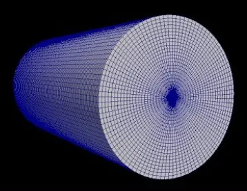
The above Mesh can be obtained in 3 ways.
One is by Meshing a cylinder, whereas the other two are by creating a wedge and using either symmetry or wedge boundary conditions on it.
BlockMeshdict file
FoamFile
{
    format      ascii;
    class       dictionary;
    object      blockMeshDict;
}
convertToMeters 1;
r 0.500000;
l 200.000000;
theta 5.000000;
ct #calc "cos(degToRad($theta))";
st #calc "sin(degToRad($theta))";
nct #calc "cos(degToRad(-$theta))";
nst #calc "sin(degToRad(-$theta))";
rct #calc "$r*$ct";
rst #calc "$r*$st";
nrct #calc "$r*$nct";
nrst #calc "$r*$nst";
vertices
(
    (0 0 0)		//0
    (0 $nrct $nrst)	//1
    (0 $rct $rst)	//2
    ($l 0 0)		//3
    ($l $nrct $nrst)	//4
    ($l $rct $rst)	//5
);
blocks
(
    hex (1 4 5 2 0 3 3 0) (400 1 10) simpleGrading (1 1 5)
);
edges
(
    arc 1 2 (0 $r 0)
    arc 4 5 ($l $r 0)
);
boundary
(
    inlet
    {
        type patch;
        faces
        (
            (0 1 2 0)
        );
    }
    outlet
    {
        type patch;
        faces
        (
            (3 5 4 3)
        );
    }
    bottomside
    {
        type wedge;
        faces
        (
            (0 3 4 1)
        );
    }
    topside
    {
        type wedge;
        faces
        (
            (0 2 5 3)
        );
    }
    fixedWalls
    {
        type wall;
        faces
        (
            (1 4 5 2)
        );
    }
    axis
    {
    	type empty;
    	faces
    	(
    	    (0 3 3 0)
    	);
    }
);
mergePatchPairs
(
);
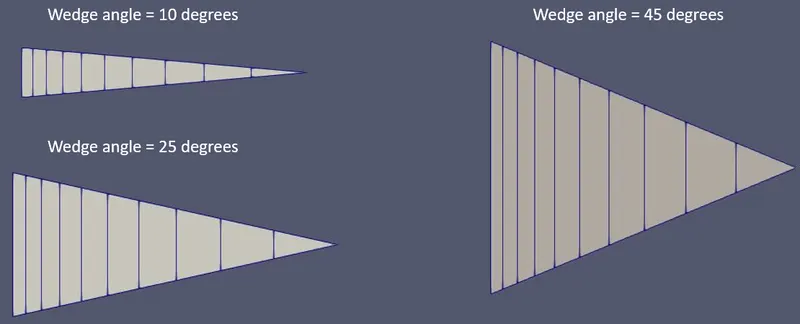
In the above code, the value of theta (10,25,45 degrees), and the boundary condition type (Wedge or symmetry) of the top and bottom side must be changed as per requirement.
Run blockMesh, open paraFoam, and verify if the Geometry generated is correct.
Step 3: Update the Initial conditions, Boundary conditions, and Constants
3.1 - Pressure
Pressure conditions are specified at all the relevant boundaries.
/*--------------------------------*- C++ -*----------------------------------*
  =========                 |
  \      /  F ield         | OpenFOAM: The Open Source CFD Toolbox
   \    /   O peration     | Website:  https://openfoam.org
    \  /    A nd           | Version:  9
     \/     M anipulation  |
*---------------------------------------------------------------------------*/
FoamFile
{
    format      ascii;
    class       volScalarField;
    object      p;
}
// * * * * * * * * * * * * * * * * * * * * * * * * * * * * * * * * * * * * * //

dimensions      [0 2 -2 0 0 0 0];

internalField   uniform 0;

boundaryField
{
    inlet
    {
        type            zeroGradient;
    }

    outlet
    {
        type            fixedValue;
        value		uniform 0;
    }
    bottomside
    {
        type 		wedge;
    }
    topside
    {
        type 		wedge;
    }
    fixedWalls
    {
        type 		zeroGradient;
    }
    axis
    {
    	type 		empty;
    }

}

// ************************************************************************* //
3.2 - Velocity
Velocity, if any, is specified at all the relevant boundaries.
/*--------------------------------*- C++ -*----------------------------------*
  =========                 |
  \      /  F ield         | OpenFOAM: The Open Source CFD Toolbox
   \    /   O peration     | Website:  https://openfoam.org
    \  /    A nd           | Version:  9
     \/     M anipulation  |
*---------------------------------------------------------------------------*/
FoamFile
{
    format      ascii;
    class       volVectorField;
    object      U;
}
// * * * * * * * * * * * * * * * * * * * * * * * * * * * * * * * * * * * * * //

dimensions      [0 1 -1 0 0 0 0];

internalField   uniform (0 0 0);

boundaryField
{
    inlet
    {
        type            fixedValue;
        value           uniform (21 0 0);
    }
    outlet
    {
        type            zeroGradient;

    }
    bottomside
    {
        type 		wedge;
    }
    topside
    {
        type 		wedge;
    }
    fixedWalls
    {
        type 		noSlip;
    }
    axis
    {
    	type 		empty;
    }
}

// ************************************************************************* //
3.3 - Transport properties
Kinematic Viscosity is specified here, in this case, it is 0.01.
/*--------------------------------*- C++ -*----------------------------------*
  =========                 |
  \      /  F ield         | OpenFOAM: The Open Source CFD Toolbox
   \    /   O peration     | Website:  https://openfoam.org
    \  /    A nd           | Version:  9
     \/     M anipulation  |
*---------------------------------------------------------------------------*/
FoamFile
{
    format      ascii;
    class       dictionary;
    location    "constant";
    object      transportProperties;
}
// * * * * * * * * * * * * * * * * * * * * * * * * * * * * * * * * * * * * * //

nu              [0 2 -1 0 0 0 0] 0.01;


// ************************************************************************* //
3.4 - ControlDict
Parameters like run time, start time, end time, timestep etc.. are edited here.
/*--------------------------------*- C++ -*----------------------------------*
  =========                 |
  \      /  F ield         | OpenFOAM: The Open Source CFD Toolbox
   \    /   O peration     | Website:  https://openfoam.org
    \  /    A nd           | Version:  9
     \/     M anipulation  |
*---------------------------------------------------------------------------*/
FoamFile
{
    format      ascii;
    class       dictionary;
    location    "system";
    object      controlDict;
}
// * * * * * * * * * * * * * * * * * * * * * * * * * * * * * * * * * * * * * //

application     icoFoam;

startFrom       startTime;

startTime       0;

stopAt          endTime;

endTime         10;

deltaT          0.01;

writeControl    runTime;

writeInterval   0.1;

purgeWrite      0;

writeFormat     ascii;

writePrecision  6;

writeCompression off;

timeFormat      general;

timePrecision   6;

runTimeModifiable true;


// ************************************************************************* //
3.5 Post-processing
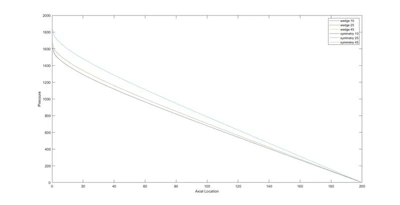
icoFoam is the solver to be used. The obtained results can be visualized in ParaView using the para form command.
The data for each case of the above-mentioned cases is extracted as a CSV file and necessary plots have been plotted using MATLAB.
Velocity variation along the axial location
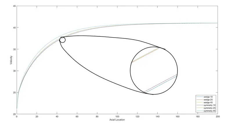
From the above plot, it can be seen that velocity stabilizes around 130m and is around 40m/s i.e, the hydrodynamic length is around 130m and the maximum velocity is around 40m/s. These results go in hand with the Analytical solution, as the maximum velocity is at the centre and is usually twice the inlet velocity.
It can also be seen that there is not much difference in velocity between the symmetric and wedge boundary condition cases.
Pressure variation along the axial location
Velocity variation in the radial direction at an axial location of 195m
An axial location of 195m means that the flow is fully developed and is shown below
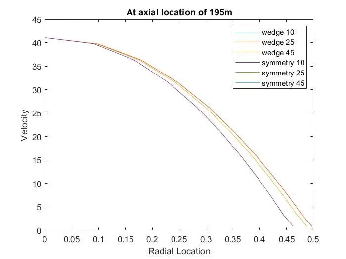
The above graph can be validated with the picture in Laminar flow through a pipe of uniform circular cross-section section.
It can also be seen that the maximum velocity is more than 40m/s.
Shear Stress variation in the radial direction at an axial location of 195m
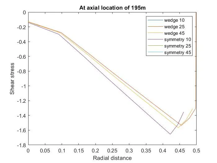
In the above graph, it can be seen that the shear stress decreases as one moves towards the wall, this seems wrong. The graph is such because of the sign convention, it is to be noted that the shear stress is in a negative direction, thus the graph's anomaly. The shear stress becomes almost zero at the wall, as there is a negligible velocity gradient.