Week 8 - Simulation of a backward facing step in OpenFOAM
Problem Statement:
- To simulate an incompressible-laminar-viscous flow through the backward facing step geometry.
CASE SETUP:
Case 1 - Simulate the flow without using any grading factor (i.e., GF = 1)
Case 2 - Simulate the flow with grading factor of 0.2. The cells should be finer near the walls (includig the step wall).
Solver
icoFoam solves the incompressible laminar Navier-Stokes equations using the PISO algorithm. The code is inherently transient, requiring an initial condition (such as zero velocity) and boundary conditions.
The solver uses the PISO algorithm to solve the continuity equation:
and momentum equation:
Where:
| u | = | Velocity |
| p | = | Kinematic pressure |
Input requirements
Mandatory fields:
- p: kinematic pressure [m2/s2]
- U: velocity [m/s]
Process setup steps in OpenFoam
- Initially directory named cavity from icoFoam folder inside category incompressible is copied to 'FOAM_RUN' folder of OpenFoam.
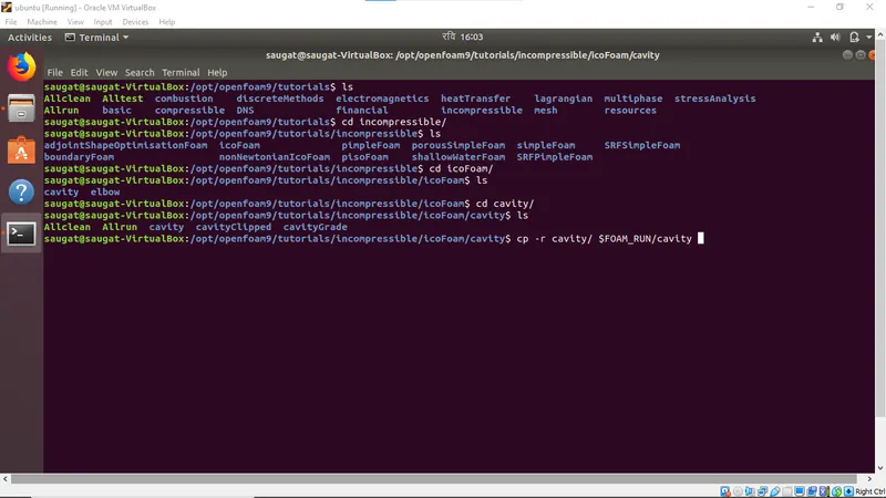
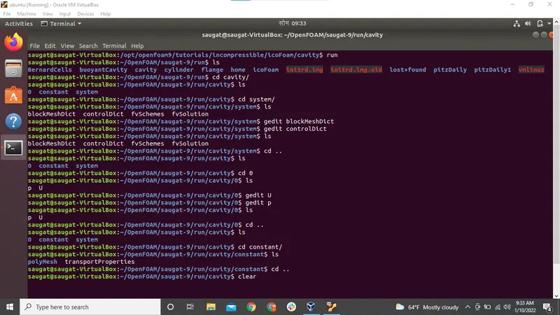
- Then navigate to run folder using 'run' command. The cavity directory consist of three folder :
- 0 - initial condition
- constant folder - it has predefined constant used to solve the governing equation and the polymesh file
- system folder - It has solution controls named :
- blockMeshDict : to edit the mesh
- controlDict: to edit the time step
- fvSchemes: It defines numercial scheme used to solve particular governing equation
- fvSolution: The equation solvers, tolerances and algorithms are controlled from the fvSolution dictionary.
- Now edit the blockmesh, controldict and initial condition for U and p inside the 0 directory as shown below
blockMeshdict without grading
/*--------------------------------*- C++ -*----------------------------------*\
  =========                 |
  \\      /  F ield         | OpenFOAM: The Open Source CFD Toolbox
   \\    /   O peration     | Website:  https://openfoam.org
    \\  /    A nd           | Version:  9
     \\/     M anipulation  |
\*---------------------------------------------------------------------------*/
FoamFile
{
    format      ascii;
    class       dictionary;
    object      blockMeshDict;
}
// * * * * * * * * * * * * * * * * * * * * * * * * * * * * * * * * * * * * * //

convertToMeters 1;

vertices
(
    (0 0 0)//0
    (0.08 0 0)//1
    (0.08 0.005 0)//2
    (0 0.005 0)//3
    (0.08 0.01 0)//4
    (0 0.01 0)//5
    (0.2 0.01 0)//6
    (0.2 0.005 0)//7
    (0.2 0 0)//8
    (0.2 -0.01 0)//9
    (0.08 -0.01 0)//10

    (0 0 0.1)//11
    (0.08 0 0.1)//12
    (0.08 0.005 0.1)//13
    (0 0.005 0.1)//14
    (0.08 0.01 0.1)//15
    (0 0.01 0.1)//16
    (0.2 0.01 0.1)//17
    (0.2 0.005 0.1)//18
    (0.2 0 0.1)//19
    (0.2 -0.01 0.1)//20
    (0.08 -0.01 0.1)//21
);

blocks
(
    hex (0 1 2 3 11 12 13 14) (80 5 1) simpleGrading (1 1 1)//block1
    hex (3 2 4 5 14 13 15 16) (80 5 1) simpleGrading (1 1 1)//block2
    hex (2 7 6 4 13 18 17 15) (120 5 1) simpleGrading (1 1 1)//block3
    hex (1 8 7 2 12 19 18 13) (120 5 1) simpleGrading (1 1 1)//block4
    hex (10 9 8 1 21 20 19 12) (120 10 1) simpleGrading (1 1 1)//block5
);

edges
(
);

boundary
(
    inlet
    {
        type patch;
        faces
        (
            (0 11 14 3)
            (3 14 16 5)
        );
    }
    outlet
    {
        type patch;
        faces
        (
            (9 8 19 20)
	    (8 7 18 19)
	    (7 6 17 18)
);
    }
No_Slip_Walls
    {
        type wall;
        faces
        (
            (16 15 4 5) //top wall
            (15 17 6 4)

            (10 21 12 1) //step side

            (11 0 1 12)   //bottomwall
            (21 10 9 20)
);
    }

    frontAndBack
    {
        type empty;
        faces
        (
            (14 13 15 16)
            (11 12 13 14)
            (21 20 19 12)// Front side
            (12 19 18 13)
            (13 18 17 15)


            (0 3 2 1)
            (3 5 4 2)
            (2 4 6 7) //Back side
            (1 2 7 8)
            (10 1 8 9)
        );
    }
);

mergePatchPairs
(
);

// ************************************************************************* //
initial condition for velocity is redefined as below:
/*--------------------------------*- C++ -*----------------------------------*\
  =========                 |
  \\      /  F ield         | OpenFOAM: The Open Source CFD Toolbox
   \\    /   O peration     | Website:  https://openfoam.org
    \\  /    A nd           | Version:  9
     \\/     M anipulation  |
\*---------------------------------------------------------------------------*/
FoamFile
{
    format      ascii;
    class       volVectorField;
    object      U;
}
// * * * * * * * * * * * * * * * * * * * * * * * * * * * * * * * * * * * * * //

dimensions      [0 1 -1 0 0 0 0];

internalField   uniform (0 0 0);

boundaryField
{
    inlet
    {
        type            fixedValue;
        value           uniform (1 0 0);
    }

    outlet
    {
        type            zeroGradient;
    }

    No_Slip_Walls
    {
        type            noSlip;

    }

    frontAndBack
    {
        type            empty;
    }
}

// ************************************************************************* //
initial condition for pressure is redefined as below:
/*--------------------------------*- C++ -*----------------------------------*\
  =========                 |
  \\      /  F ield         | OpenFOAM: The Open Source CFD Toolbox
   \\    /   O peration     | Website:  https://openfoam.org
    \\  /    A nd           | Version:  9
     \\/     M anipulation  |
\*---------------------------------------------------------------------------*/
FoamFile
{
    format      ascii;
    class       volScalarField;
    object      p;
}
// * * * * * * * * * * * * * * * * * * * * * * * * * * * * * * * * * * * * * //

dimensions      [0 2 -2 0 0 0 0];

internalField   uniform 0;

boundaryField
{
    inlet
    {
        type            zeroGradient;
    }

    outlet
    {
        type            fixedValue;
  	value 		uniform 0;
    }

   No_Slip_Walls
    {
        type            zeroGradient;
    }
    frontAndBack
    {
        type            empty;
    }
}

// ************************************************************************* //
blockMeshdict with grading of 0.2
/*--------------------------------*- C++ -*----------------------------------*\
  =========                 |
  \\      /  F ield         | OpenFOAM: The Open Source CFD Toolbox
   \\    /   O peration     | Website:  https://openfoam.org
    \\  /    A nd           | Version:  9
     \\/     M anipulation  |
\*---------------------------------------------------------------------------*/
FoamFile
{
    format      ascii;
    class       dictionary;
    object      blockMeshDict;
}
// * * * * * * * * * * * * * * * * * * * * * * * * * * * * * * * * * * * * * //

convertToMeters 1;

vertices
(
    (0 0 0)//0
    (0.08 0 0)//1
    (0.08 0.005 0)//2
    (0 0.005 0)//3
    (0.08 0.01 0)//4
    (0 0.01 0)//5
    (0.2 0.01 0)//6
    (0.2 0.005 0)//7
    (0.2 0 0)//8
    (0.2 -0.01 0)//9
    (0.08 -0.01 0)//10

    (0 0 0.1)//11
    (0.08 0 0.1)//12
    (0.08 0.005 0.1)//13
    (0 0.005 0.1)//14
    (0.08 0.01 0.1)//15
    (0 0.01 0.1)//16
    (0.2 0.01 0.1)//17
    (0.2 0.005 0.1)//18
    (0.2 0 0.1)//19
    (0.2 -0.01 0.1)//20
    (0.08 -0.01 0.1)//21
);

blocks
(
    hex (0 1 2 3 11 12 13 14) (80 5 1) simpleGrading (0.2 5  1)//block1
    hex (3 2 4 5 14 13 15 16) (80 5 1) simpleGrading (0.2 0.2 1)//block2
    hex (2 7 6 4 13 18 17 15) (120 5 1) simpleGrading (5 0.2 1)//block3
    hex (1 8 7 2 12 19 18 13) (120 5 1) simpleGrading (5 5 1)//block4
    hex (10 9 8 1 21 20 19 12) (120 10 1) simpleGrading (5 5 1)//block5
);

edges
(
);

boundary
(
    inlet
    {
        type patch;
        faces
        (
            (0 11 14 3)
            (3 14 16 5)
        );
    }
    outlet
    {
        type patch;
        faces
        (
            (9 8 19 20)
	    (8 7 18 19)
	    (7 6 17 18)
);
    }
No_Slip_Walls
    {
        type wall;
        faces
        (
            (16 15 4 5) //top wall
            (15 17 6 4)

            (10 21 12 1) //step side

            (11 0 1 12)   //bottomwall
            (21 10 9 20)
);
    }

    frontAndBack
    {
        type empty;
        faces
        (
            (14 13 15 16)
            (11 12 13 14)
            (21 20 19 12)// Front side
            (12 19 18 13)
            (13 18 17 15)


            (0 3 2 1)
            (3 5 4 2)
            (2 4 6 7) //Back side
            (1 2 7 8)
            (10 1 8 9)
        );
    }
);

mergePatchPairs
(
);

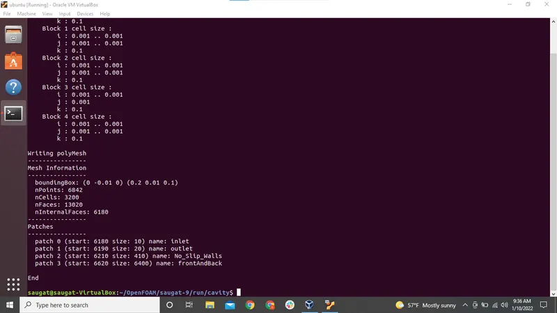
// ************************************************************************* //- After making changes to initial conditions and blockMeshdict, mesh is generated using 'blockMesh' command
- blockMesh generates mesh and gives output as shown below:
- 'checkMesh' command is used to ensure the meshing is done correctly
- output is shown below:
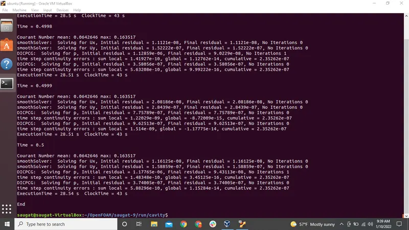
- The solver 'icoFoam' is used to solve this problem
- The output is shown below
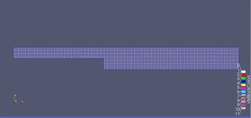
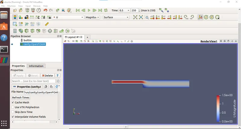
Output from paraFoam: (without grading)
- Mesh without grading:
- Velocity distribution inside domain:
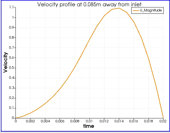
- Velocity profile at 0.085m away from inlet:
With grading of 0.2
- Mesh with grading
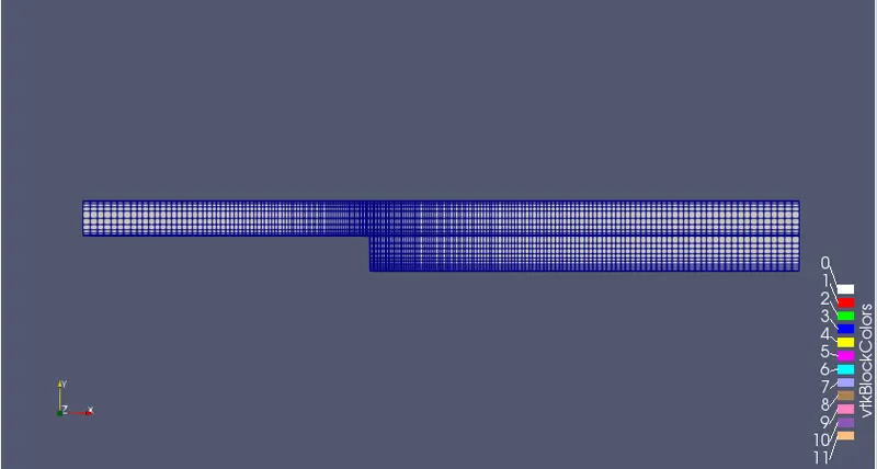
Here we can see mesh near to wall is fine than the mesh at other positions.
- Velocity distribution inside domain:
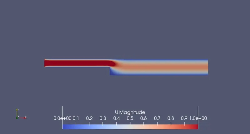
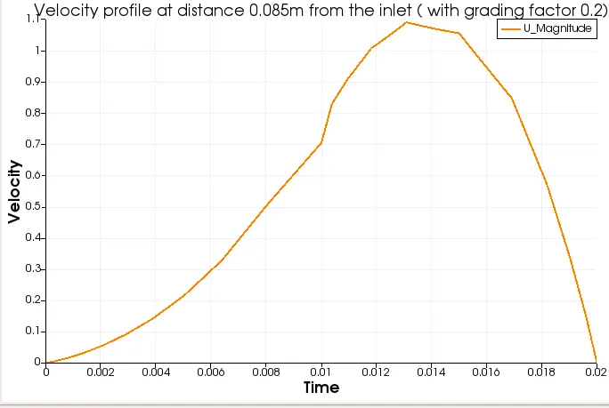
- Velocity profile at 0.085m away from inlet: with grading
- Explain why Grading/Growth factor is essential for meshing.
Grading factor is the ratio of size of last cell to size of first cell in the mesh
Grading factor = `(size__of__LAST__cell)/(size__of__FIRST__cell`
It is an important parameter in CFD as it helps to make mesh fine or coarse according to the requirements. Fine mesh can result in much accurate solution incomparison to coarse mesh. But it comes with more computer time to solve the particular problem, as more cell in the mesh means more computing time is required. The grading factor depends on user requirement. A CFD engineer can define grading factor on the basis of required accuracy of the solution. Fine mesh can be used in region with higher accuracy requirement whereas coarse mesh is suitable for regions with lower accuracy.
In this problem, while applying grading factor of 0.2 near the walls the output of velocity profile seems more accurate. But there is not much difference. Hence grading factor is not compulsory for this particular problem.