Week 11 - Simulation of Flow through a pipe in OpenFoam
Problem Statement:
- To simulate an axi-symmetric flow by applying the wedge boundary condition. The flow is laminar and flows through a constant cross-section pipe at an inlet Reynold's number of 2100.
- To validate results with the Hagen- Poiseuille's equations for the fully developed flow.
- To write code in Matlab to automate the generation of blockMeshDict file.
Expected Results
- Validate Hydro-dynamic length with the numerical result
- Validate the fully developed flow velocity profile with its analytical profile
- Validate maximum velocity and pressured drop for fully developed flow
- Post-process Shear stress and validate wall shear stress for fully developed flow
Laminar flow in pipes:
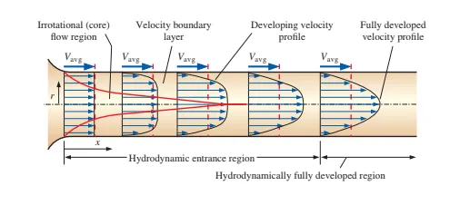
Consider a fluid entering a circular pipe at a uniform velocity. Because of the no-slip condition, the fluid particles in the layer in contact with the wall of the pipe come to a complete stop. This layer also causes the fluid particles in the adjacent layers to slow down gradually as a result of friction. To make up for this velocity reduction, the velocity of the fluid at the midsec-
tion of the pipe has to increase to keep the mass flow rate through the pipe constant. As a result, a velocity gradient develops along the pipe.
Different region of the flow is developed inside the pipe:
- Velocity boundary layer: The region of the flow in which the effects of the viscous shearing forces
caused by fluid viscosity are felt. - irrotational(core) flow region: The region of flow in which the frictional effects are negligible and the
velocity remains essentially constant in the radial direction.
The thickness of this boundary layer increases in the flow direction until the boundary layer reaches the pipe center and thus fills the entire pipe, as shown in Fig and the velocity becomes fully developed a little farther downstream. The region from the pipe inlet to the point at which the velocity profile is fully developed is called the hydrodynamic entrance region and the length of this region is called the hydrodynamic entry length Lh. Flow in the entrance region is called hydrodynamically developing flow since this is the region where the velocity profile develops. The region beyond the entrance region in which the velocity profile is fully developed and remains unchanged is called the hydrodynamically fully developed region.
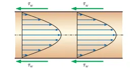
In the fully developed flow region of a pipe, the velocity profile does not change downstream, and thus the wall shear stress remains constant as well.
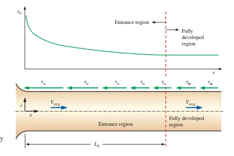
The variation of wall shear stress in the flow direction for flow in a pipe from the entrance region into the fully developed region.
Entry length:
In laminar flow, the nondimensional hydrodynamic entry length is given approximately as
`Le = 0.06*Re*D`
Hagen- Poiseuille's equation
According to Hagen- Poiseuille's equation, for a specified flow rate, the pressure drops and thus the required pumping power is proportional to the length of the pipe and the viscosity of the fluid, but it is inversely proportional to the fourth power of the radius (or diameter) of the pipe.
`V_(avg)*A = (Deltap piD^4 )/ (128muL )`
Flow parameters:
Assumption:
- Steady, laminar, incompressible flow of fluid with constant properties in the fully developed region of a straight circular pipe.
- Axi-symmetric flow
Analytical solution:
Reynolds number(Re) = 2100
Kinematic viscocity(`nu`) = `0.8927**10^-6 m^2s^-1`
Diameter of pipe(D) = 0.025m
`V_(avg) = (Re*mu)/(rho*D) = 0.075 ms^-1`
Hydrodynamic entrance length, `L_e = 0.06*Re*D = 2.625m`
Since after L_e distance the flow is fully developed therefore actual length of pipe is :
`L = L_e +0.5` = 3.125m
`Deltap = 32muLV/D^2 = 10.6779pa`
kinematic `Delta p` `= (Deltap )/ rho`= 0.0107m
Wedge boundary condition:
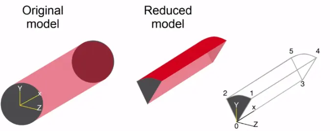
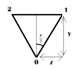
here:
the wedge angle in degrees
z = (D/2)*sind(theta/2);
y = (D/2)*cosd(theta/2);
icoFoam solver:
Here icoFoam solver is used to solve the flow across the pipe.
The solver uses the PISO algorithm to solve the continuity equation:
and momentum equation:
Where:
| u | = | Velocity |
| p | = |
Kinematic pressure |
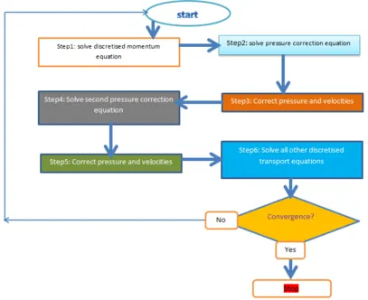
Flow chart for piso algorithm ( source: wikipedia)
Code in Matlab to automate the generation of blockMeshDict file:
clear all
close all
clc

%creating blockMeshDict file for wedge creation

%defining input values
D = 0.025; %diameter of pipe in meters
r = D/2;
Re = 2100;          %reynold's number
L_e = 0.05*Re*D;    %hydrodynamic entrance length
L = L_e+0.5;        %length of the pipe
mu = 0.89e-3;       %viscosity of water at 25 deg C
rho = 997;          %density of water at 25 deg C
nu = mu/rho;        %kinematic viscosity of water at 25 deg C

%analytical solution of velocity and pressure drop
v_avg = (Re*mu)/(rho*D);        %average velocity
v_max = 2*v_avg;                %maximum velocity inside pipe
p_drop = (32*mu*v_avg*L)/(D^2); %pressure drop across pipe
kin_p = p_drop/rho;             %kinematic pressure

%defining the wedge angle in degrees
theta = 4;

%defining co-ordinates for wedge creation
z = (D/2)*sind(theta/2);
y = (D/2)*cosd(theta/2);

%defining grading along x,y & z direction
g_x = 1;
g_y = 0.1;
g_z = 1;


%file parsing for blockMeshDict file

f1 = fopen('wedgemesh.txt','w');

%header
fprintf(f1,'%s','/*--------------------------------*- C++ -*----------------------------------*\');
fprintf(f1,'\n');
fprintf(f1,'%s','  =========                 |');
fprintf(f1,'\n');
fprintf(f1,'%s','  \\      /  F ield         | OpenFOAM: The Open Source CFD Toolbox');
fprintf(f1,'\n');
fprintf(f1,'%s','   \\    /   O peration     | Website:  https://openfoam.org');
fprintf(f1,'\n');
fprintf(f1,'%s','    \\  /    A nd           | Version:  9');
fprintf(f1,'\n');
fprintf(f1,'%s','     \\/     M anipulation  |');
fprintf(f1,'\n');
fprintf(f1,'%s','\*---------------------------------------------------------------------------*/');
fprintf(f1,'\n');
fprintf(f1,'%s','FoamFile');
fprintf(f1,'\n');
fprintf(f1,'%s','{');
fprintf(f1,'\n');
fprintf(f1,'%s','    format      ascii;');
fprintf(f1,'\n');
fprintf(f1,'%s','    class       dictionary;');
fprintf(f1,'\n');
fprintf(f1,'%s','    object      blockMeshDict;');
fprintf(f1,'\n');
fprintf(f1,'%s','}');
fprintf(f1,'\n');
fprintf(f1,'%s','// * * * * * * * * * * * * * * * * * * * * * * * * * * * * * * * * * * * * * //');
fprintf(f1,'\n');
fprintf(f1,'\n');
fprintf(f1,'%s','convertToMeters 1;');
fprintf(f1,'\n');
fprintf(f1,'\n');

%vertices creation
fprintf(f1,'%s','vertices');
fprintf(f1,'\n');
fprintf(f1,'%s\n','(');
fprintf(f1,'%s(%d %d %d)%s\n',blanks(5),0,0,0,'//[0]');
fprintf(f1,'%s(%d %d %d)%s\n',blanks(5),0,y,z,'//[1]');
fprintf(f1,'%s(%d %d %d)%s\n',blanks(5),0,y,-z,'//[2]');
fprintf(f1,'%s(%d %d %d)%s\n',blanks(5),L,0,0,'//[3]');
fprintf(f1,'%s(%d %d %d)%s\n',blanks(5),L,y,z,'//[4]');
fprintf(f1,'%s(%d %d %d)%s\n',blanks(5),L,y,-z,'//[5]');
fprintf(f1,'%s\n',');');
fprintf(f1,'\n');

%block creation
fprintf(f1,'blocks');
fprintf(f1,'\n');
fprintf(f1,'(\n');
fprintf(f1,'%s %s',blanks(5),'hex(0 3 5 2 0 3 4 1) (400 60 1) simpleGrad(1 0.1 1)');
fprintf(f1,'%s\n',');');
fprintf(f1,'\n');

%edge creation
fprintf(f1,'egde\n');
fprintf(f1,'(\n');
fprintf(f1,'%s %s\n',blanks(5),'arc 1 2(0 0.0125 0)');
fprintf(f1,'%s %s\n',blanks(5),'arc 4 5(3.125 0.0125 0)');
fprintf(f1,'%s\n',');');
fprintf(f1,'\n');

%boundary creation
fprintf(f1,'boundary\n');
fprintf(f1,'(\n');

%inlet
fprintf(f1,'%s %s\n',blanks(5),'inlet');
fprintf(f1,'%s %s\n',blanks(5),'{');
fprintf(f1,'%s %s\n',blanks(10),'type patch');
fprintf(f1,'%s %s\n',blanks(10),'faces');
fprintf(f1,'%s %s\n',blanks(10),'(');
fprintf(f1,'%s (%d %d %d %d)\n',blanks(15),0,0,1,2);
fprintf(f1,'%s %s\n',blanks(10),');');
fprintf(f1,'%s %s\n',blanks(5),'{');
fprintf(f1,'\n');

%outlet face
fprintf(f1,'%s %s\n',blanks(5),'outlet');
fprintf(f1,'%s %s\n',blanks(5),'{');
fprintf(f1,'%s %s\n',blanks(10),'type patch');
fprintf(f1,'%s %s\n',blanks(10),'faces');
fprintf(f1,'%s %s\n',blanks(10),'(');
fprintf(f1,'%s (%d %d %d %d)\n',blanks(15),5,3,3,4);
fprintf(f1,'%s %s\n',blanks(10),');');
fprintf(f1,'%s %s\n',blanks(5),'}');
fprintf(f1,'\n');

%top face
fprintf(f1,'%s %s\n',blanks(5),'No_Slip_Walls');
fprintf(f1,'%s %s\n',blanks(5),'{');
fprintf(f1,'%s %s\n',blanks(10),'type wall');
fprintf(f1,'%s %s\n',blanks(10),'faces');
fprintf(f1,'%s %s\n',blanks(10),'(');
fprintf(f1,'%s (%d %d %d %d)\n',blanks(15),2,1,4,5);
fprintf(f1,'%s %s\n',blanks(10),');');
fprintf(f1,'%s %s\n',blanks(5),'}');
fprintf(f1,'\n');

%wedge front
fprintf(f1,'%s %s\n',blanks(5),'front');
fprintf(f1,'%s %s\n',blanks(5),'{');
fprintf(f1,'%s %s\n',blanks(10),'type wedge');
fprintf(f1,'%s %s\n',blanks(10),'faces');
fprintf(f1,'%s %s\n',blanks(10),'(');
fprintf(f1,'%s (%d %d %d %d)\n',blanks(15),0,3,4,1);
fprintf(f1,'%s %s\n',blanks(10),');');
fprintf(f1,'%s %s\n',blanks(5),'}');
fprintf(f1,'\n');

%wedge back
fprintf(f1,'%s %s\n',blanks(5),'back');
fprintf(f1,'%s %s\n',blanks(5),'{');
fprintf(f1,'%s %s\n',blanks(10),'type wedge');
fprintf(f1,'%s %s\n',blanks(10),'faces');
fprintf(f1,'%s %s\n',blanks(10),'(');
fprintf(f1,'%s (%d %d %d %d)\n',blanks(15),0,3,5,2);
fprintf(f1,'%s %s\n',blanks(10),');');
fprintf(f1,'%s %s\n',blanks(5),'}');
fprintf(f1,'\n');

%wedge axis
fprintf(f1,'%s %s\n',blanks(5),'axis');
fprintf(f1,'%s %s\n',blanks(5),'{');
fprintf(f1,'%s %s\n',blanks(10),'type empty');
fprintf(f1,'%s %s\n',blanks(10),'faces');
fprintf(f1,'%s %s\n',blanks(10),'(');
fprintf(f1,'%s (%d %d %d %d)\n',blanks(15),0,3,4,1);
fprintf(f1,'%s %s\n',blanks(10),');');
fprintf(f1,'%s %s\n',blanks(5),'}');
fprintf(f1,'\n');
fprintf(f1,');\n');


%patchpairs
fprintf(f1,'mergePatchPair\n');
fprintf(f1,'(\n');
fprintf(f1,');\n');
fprintf(f1,'%s','// * * * * * * * * * * * * * * * * * * * * * * * * * * * * * * * * * * * * * //');

fclose(f1);
The above matlab code generates input for blockMeshdict file which has wedge boundary condition as defined below in boundary section.
blockMeshdict:
/*--------------------------------*- C++ -*----------------------------------*\
  =========                 |
  \\      /  F ield         | OpenFOAM: The Open Source CFD Toolbox
   \\    /   O peration     | Website:  https://openfoam.org
    \\  /    A nd           | Version:  9
     \\/     M anipulation  |
\*---------------------------------------------------------------------------*/
FoamFile
{
    format      ascii;
    class       dictionary;
    object      blockMeshDict;
}
// * * * * * * * * * * * * * * * * * * * * * * * * * * * * * * * * * * * * * //

convertToMeters 1;

vertices
(
     (0 0 0)//[0]
     (0 1.249239e-02 4.362437e-04)//[1]
     (0 1.249239e-02 -4.362437e-04)//[2]
     (3.125000e+00 0 0)//[3]
     (3.125000e+00 1.249239e-02 4.362437e-04)//[4]
     (3.125000e+00 1.249239e-02 -4.362437e-04)//[5]
);

blocks
(
      hex(0 3 5 2 0 3 4 1) (400 60 1) simpleGrad(1 0.1 1));

egde
(
      arc 1 2(0 0.0125 0)
      arc 4 5(3.125 0.0125 0)
);

boundary
(
      inlet
      {
           type patch
           faces
           (
                (0 0 1 2)
           );
      {

      outlet
      {
           type patch
           faces
           (
                (5 3 3 4)
           );
      }

      No_Slip_Walls
      {
           type wall
           faces
           (
                (2 1 4 5)
           );
      }

      front
      {
           type wedge
           faces
           (
                (0 3 4 1)
           );
      }

      back
      {
           type wedge
           faces
           (
                (0 3 5 2)
           );
      }

      axis
      {
           type empty
           faces
           (
                (0 3 4 1)
           );
      }

);
mergePatchPair
(
);
// * * * * * * * * * * * * * * * * * * * * * * * * * * * * * * * * * * * * * //
Boundary condition at 0:
Velocity:
/*--------------------------------*- C++ -*----------------------------------*\
  =========                 |
  \\      /  F ield         | OpenFOAM: The Open Source CFD Toolbox
   \\    /   O peration     | Website:  https://openfoam.org
    \\  /    A nd           | Version:  9
     \\/     M anipulation  |
\*---------------------------------------------------------------------------*/
FoamFile
{
    format      ascii;
    class       volVectorField;
    object      U;
}
// * * * * * * * * * * * * * * * * * * * * * * * * * * * * * * * * * * * * * //

dimensions      [0 1 -1 0 0 0 0];

internalField   uniform (0 0 0);

boundaryField
{
    inlet
    {
        type            fixedValue;
        value           uniform (0.075 0 0);
    }

    outlet
    {
        type            zeroGradient;
    }

    No_Slip_Walls
    {
        type            noSlip;
    }
    front
    {
	type 		wedge;
    }
    back
    {
	type 		wedge;
    }
    axis
    {
	type 		empty;
    }
}

// ************************************************************************* //
Pressure:
/*--------------------------------*- C++ -*----------------------------------*\
  =========                 |
  \\      /  F ield         | OpenFOAM: The Open Source CFD Toolbox
   \\    /   O peration     | Website:  https://openfoam.org
    \\  /    A nd           | Version:  9
     \\/     M anipulation  |
\*---------------------------------------------------------------------------*/
FoamFile
{
    format      ascii;
    class       volScalarField;
    object      p;
}
// * * * * * * * * * * * * * * * * * * * * * * * * * * * * * * * * * * * * * //

dimensions      [0 2 -2 0 0 0 0];

internalField   uniform 0;

boundaryField
{
    inlet
    {
        type            zeroGradient;

    }

    outlet
    {
        type            fixedValue;
	value           uniform 0 ;
    }

    No_Slip_Walls
    {
        type            zeroGradient;
    }
    front
    {
	type 		wedge;
    }
    back
    {
	type 		wedge;
    }
    axis
    {
	type 		empty;
    }
}

// ************************************************************************* //
controlDict:
The controlDict file has input for time step and total simulation run time.
Here, `Delta t = 0.02` considering the CFL criteria for flow simulation inside a pipe.
`C =( Delta t *U)/(Deltax)`
where C is courant number,
`Delta t` is the time step,
U is the average velocity
`Delta x` is grid size
/*--------------------------------*- C++ -*----------------------------------*\
  =========                 |
  \\      /  F ield         | OpenFOAM: The Open Source CFD Toolbox
   \\    /   O peration     | Website:  https://openfoam.org
    \\  /    A nd           | Version:  9
     \\/     M anipulation  |
\*---------------------------------------------------------------------------*/
FoamFile
{
    format      ascii;
    class       dictionary;
    location    "system";
    object      controlDict;
}
// * * * * * * * * * * * * * * * * * * * * * * * * * * * * * * * * * * * * * //

application     icoFoam;

startFrom       startTime;

startTime       0;

stopAt          endTime;

endTime         50;

deltaT          0.02;

writeControl    timeStep;

writeInterval   20;

purgeWrite      0;

writeFormat     ascii;

writePrecision  6;

writeCompression off;

timeFormat      general;

timePrecision   6;

runTimeModifiable true;


// ************************************************************************* //
transportProperties:
The kinematic viscosity is redefined under transportProperties file inside the system folder of cavity.
/*--------------------------------*- C++ -*----------------------------------*\
  =========                 |
  \\      /  F ield         | OpenFOAM: The Open Source CFD Toolbox
   \\    /   O peration     | Website:  https://openfoam.org
    \\  /    A nd           | Version:  9
     \\/     M anipulation  |
\*---------------------------------------------------------------------------*/
FoamFile
{
    format      ascii;
    class       dictionary;
    location    "constant";
    object      transportProperties;
}
// * * * * * * * * * * * * * * * * * * * * * * * * * * * * * * * * * * * * * //

nu              [0 2 -1 0 0 0 0] 0.0000008927;


// ************************************************************************* //
Output:
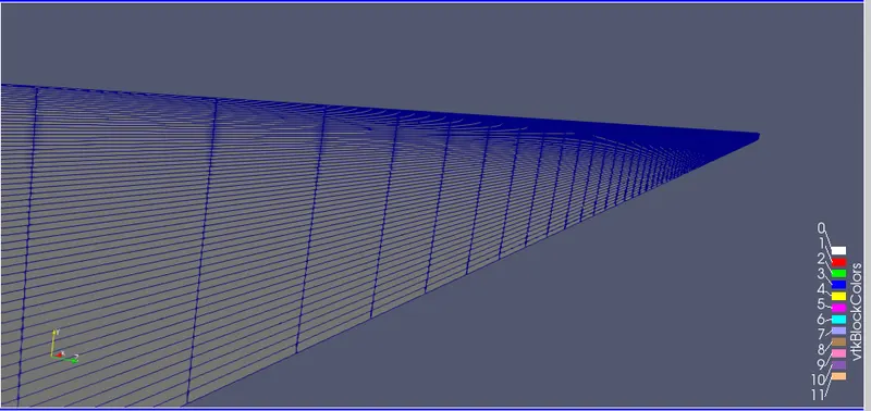
Mesh output:
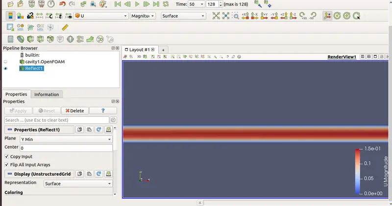
Flow properties:
Velocity distribution across the pipe:
At 0.2m from inlet:
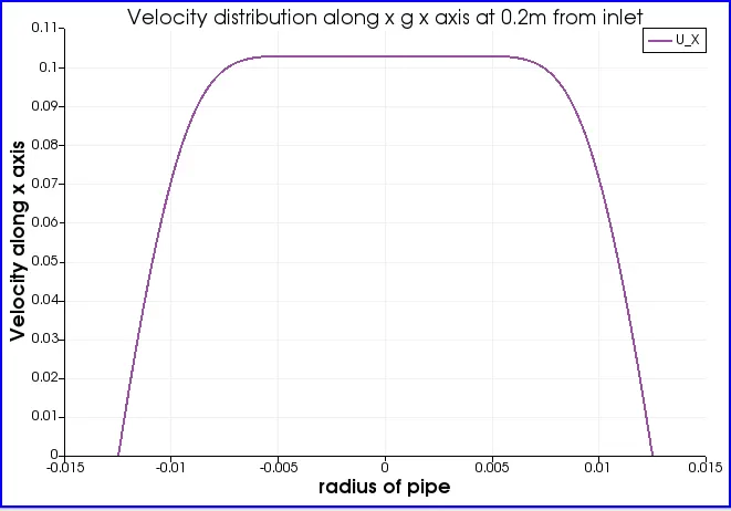
Here we can see the flow is parabolic which means flow is not fully developed which is obvious at distance 0.2m from inlet as the hydrodynamic entrance lenght is 2.75m obtained from analytical solution.
At 2.75m from inlet:
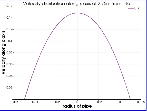
Here we can see the flow is parabolic which means the flow is fully developed and velocity is maximum at the center of the pipe and minimum near the boundary of the pipe due to no-slip condition of pipe flow.
At 3m from inlet:
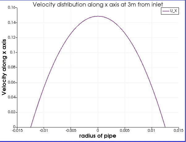
There is no change as the flow is fully developed.
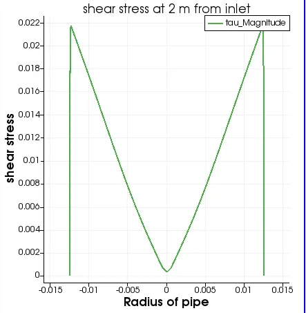
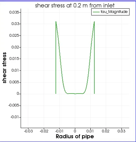
Shear stress:
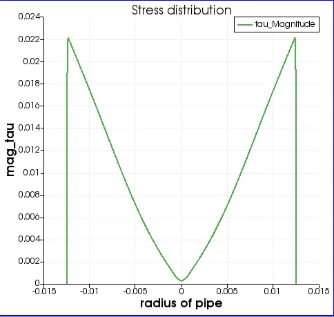
Here from the graph below we can observe shear wall stress is more near inlet and less away from inlet
We know,
`tau = mu * (du)/dy`
At 1.565 m from inlet:
At 2m from inlet:
At 0.2m from inlet:
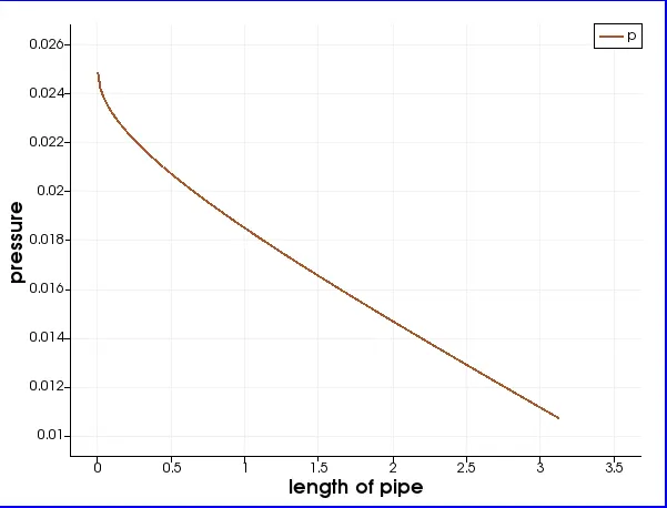
Pressure drop:
From output: `Deltap = 0.0253 - 00106 = 0.0147 m` which is nearly equal to analytical solution.
Conclusion:
- The velocity profile is parabolic after 2.75m as shown in the output above. Therefore the flow is fully developed. Hence Hydro-dynamic length is validated with the numerical result.
- The maximum velocity from the simulation is nearly equal to 0.15 m/s as shown in the graph which is same as the analytical solution.
- The pressure drop across the pipe obtained from simulation is also nearly equal to the analytical solution as shown in the pressure distribution graph across the x-axis.
- The shear stress is maximum near wall and decreases along the radius from both walls. The shear stress distribution graph proves the statement.
- The wall shear stress is greater at 0.2m from inlet incomparison to 1.565m which shows the wall shear stress variation across the pipe. Also the wall shear stress is similar for 1.565m from inlet and 2m from inlet.
Reference:
- https://www.openfoam.com/documentation/user-guide/contents
- Fluid Mechanics: Fundamental and Application 3rd edition [ Cengel & Cimbala -2014]