Week 8 - Simulation of a backward facing step in OpenFOAM
Objective:
- SImulate an incompressible laminar viscous flow through the backward facing step geometry.
- Perform transient simualtion and chooose the solver based on the given conditions
- Expalin simulation process and way of settting up the problem statement.
- Explain the changes made in the tutorial files
- Perform two cases, first with no grading factor, i.e, GF =1. Next, with grading factor=0.2, making the cells near boundary walls finer
Problem statement:
Simulate an incompressible laminar viscous flow through the backward facing step geometry.
Case 1 - Simulate the flow without using any grading factor (i.e., GF = 1)
Case 2 - Simulate the flow with grading factor of 0.2. The cells should be finer near the walls (includig the step wall).
You can use the following mesh parameters but you can feel free to modify these values.
Mesh specification
- Number of cells along the x direction (longer dimension) = 200
- Number of cells along the longer y direction = 20;
Boundary condition specification
The domain specifications are provided in the following figure.
Procedure:
- After going throught the various tutorial files, cavity problem in "/opt/openfoam9/tutorials/incompressible/icoFoam/cavity" is the rigth set up for the given problem.
- copy the cavity file and paste in the run folder by using the command" cp -r cavity $FOAM_RUN/ cavity_ex2 "
- now that we have the setup files in the right folder,we edit the system and constant folders based on the given conditions.
- "cd system" lets you inside the folder, "ls" shows the files in the folder system.
- "gedit blockMeshDict",open up the text file, where we can provide details of the geometry, mesh and grading factor.
- after all the changes, shown below, been made to the blockMeshDict, save and close the text window.
- run the mesh by typingt he command "blockMesh" to generate the mesh
- check for any errors in the mesh using the "checkMesh" command.
- once the mesh is generated, go to the controlDict file in the same folder using the commands or by navigating the files in the run folder in the file exproler.
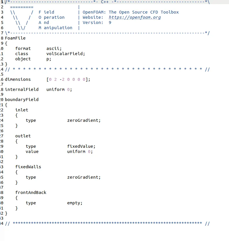
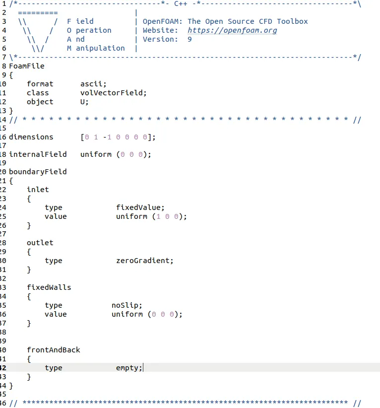
- make the changes as state below. give the boundary conditions in the folder 0, where you find U,p files
- open both files and make necessay changes required for the problem as stated below.
- After all the boundary conditins were set, stay in the same folder before simulating the problem using the command "icoFoam"
- After the convergence, to view the solution, go to paraFoam by typing the same in the command window
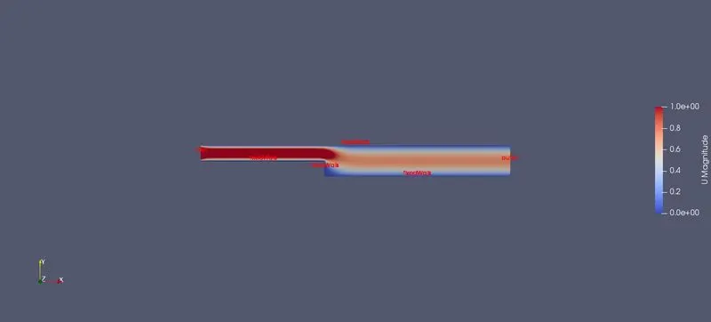
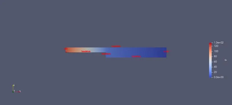
- view the pressure and velocity distributions in the render view
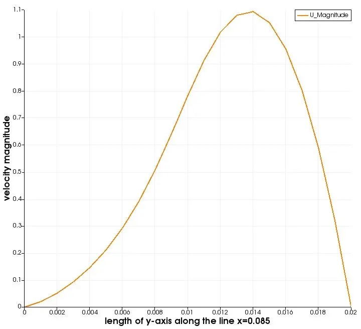
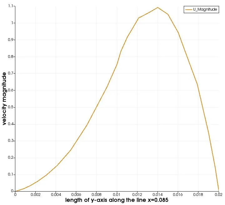
- plot the velocity distributin at x=0.085
- repeat the same procedure for the grading factor 0.2
case-1: without grading factor
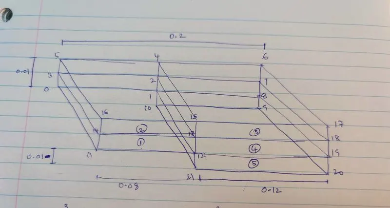
as shown in the figure divide the geometry in to the blocks and number the vertices.
blockMeshDict:
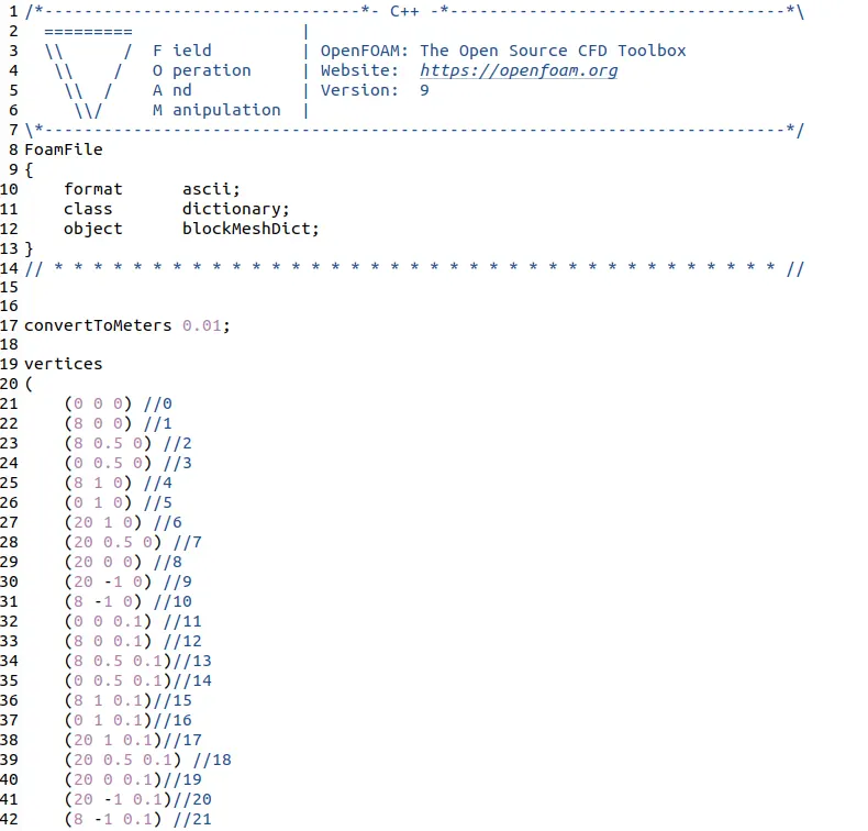
the vertices shown are defined according to the figure provided above
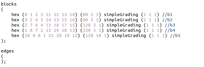
hex- the mesh consitudes of hexahedrons
(0 1 2 3 4 11 12 13 14) - defines the block and its coordiante system
simpleGrading (1 1 1)- equal spacing of cells along all directions i.e, no grading.
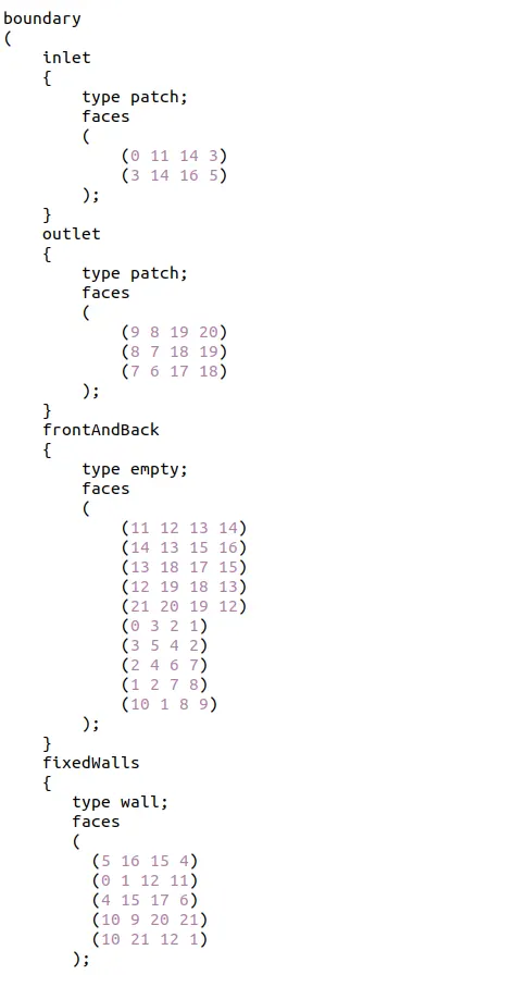
the boundary conditions were set according to the right hand thumb rule i.e, the normal vector facing outside of each face.
controlDict:
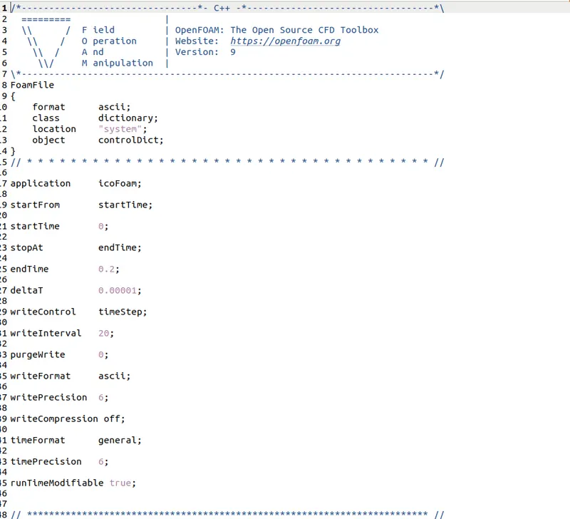
these are the changes related to silulation time and time step were made as shown in the above picture.
pressure/density:
velocity:
Mesh:
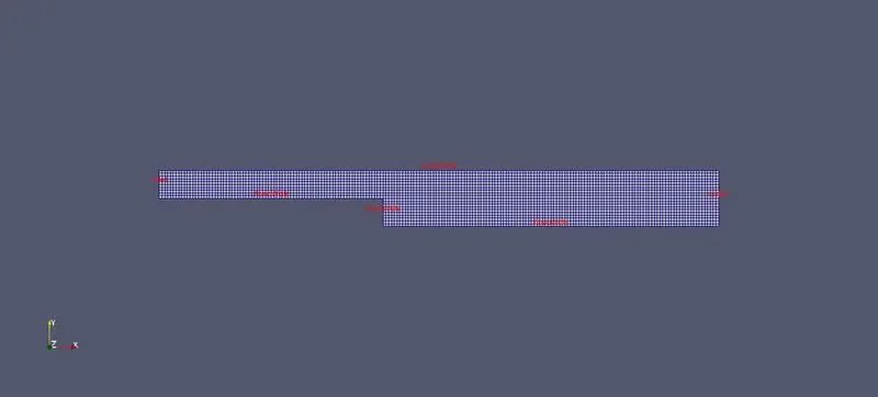
the number of nodes are adjusted to to the length of walls to form a uniform grid, refer to the blockMeshDict blocks to see the number of nodes for each block to get the uniform grid.
velocity:
pressure:
line plot :
Grading factor:
the grading factor enable the mesh to be graded or refined in specific direction. the ratio of the width of the end cell in that direction to that of stat cell
Expansion ratio= `(size of the end cell )/(size of the first cell)`
For the second case all the boundary conditions remains same, only the mesh grading near the walls changes by factor of 0.2. it is shown below the use of multi grading concept to refine the mesh near walls.
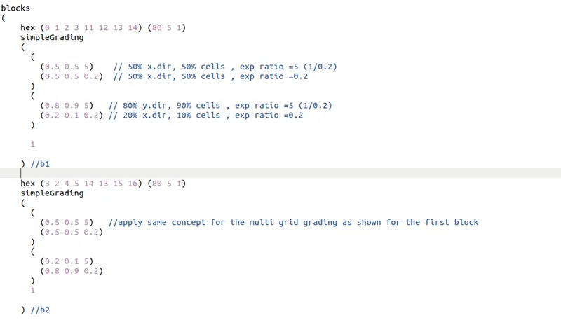
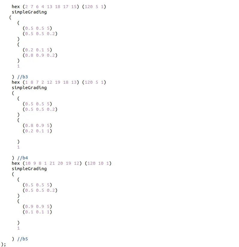
all the blocks were refined by a grading factor of 0.2 or more to form a fine mesh near the walls.
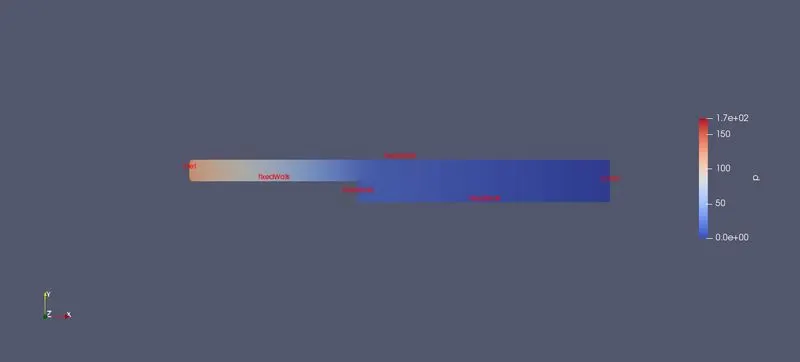
pressure:
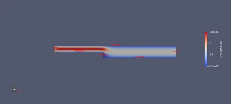
velocity:
line plot:
Conclusion:
The grading factor is essential in areas where the sudden change in flow properties occured in in domain. if there are no enough nodes to capture the change in flow properties, we get inaccurate results.Like in the above case of no grading factor the grid was uniform and there a were not enough nodes at the step wall to obtain the change in the flow propertes gives a little in accurate results where as in the case of refined mesh near wall provides more unmber of nodes near walls for the same number of total nodes in the domain to capture the change in flow properties.