Week 8 - Simulation of a backward facing step in OpenFOAM
AIM:
1) To simulate an incompressible-laminar-viscous flow through a backward facing step geometry.
2) To simulate the flow for Grading Factor = 1, 0.2 with respect to the given mesh specification.
3) To measure velocity profile at 0.085m from the inlet section of the geometry for both cases using plot over line tool.
SIMULATION PROCEDURE:
The problem statement involves incompressible laminar viscous flow and for this a suitable tutorial is chosen from the FOAM_TUTORIALS folder. Similair to our problem statement is the tutorial "cavity" with "/opt/openfoam9/tutorials/incompressible/icoFoam/cavity" as its address location. We have to copy this folder with all its contents to the FOAM_RUN folder using the command line terminal command "cp -r". 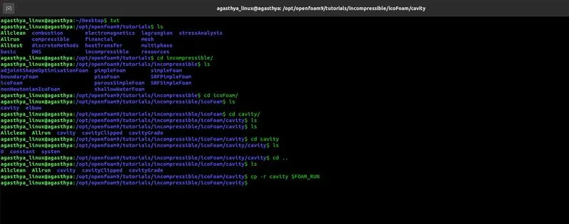
Now that we have the most relevant case-setup "cavity" copied to the FOAM_RUN folder, we can start editing it to match our problem statement more accurately. Initially we edit the "blockMesh" file in the system file to attain geometry similar to our case. After editing the blockMesh file to attain required geometry, we then run the "blockMesh" command in the cavity folder. Thereupon the paraFoam command is run for post-processing. This creates a cavity. OpenFOAM file which can be viewed and analysed in ParaView. After checking the mesh quality, we come back to cavity folder and open the "0" folder where the initial states of velocity and pressure are stored. There we alter the initial conditions to match our problem statement.
Initial state file of velocity - U:
/*--------------------------------*- C++ -*----------------------------------*\
  =========             	|
  \\  	/  F ield     	| OpenFOAM: The Open Source CFD Toolbox
   \\	/   O peration 	| Website:  https://openfoam.org
	\\  /	A nd       	| Version:  9
 	\\/ 	M anipulation  |
\*---------------------------------------------------------------------------*/
FoamFile
{
	format  	ascii;
	class   	volVectorField;
	object  	U;
}
// * * * * * * * * * * * * * * * * * * * * * * * * * * * * * * * * * * * * * //

dimensions  	[0 1 -1 0 0 0 0];

internalField   uniform (0 0 0);

boundaryField
{
	inlet
	{
    	type        	fixedValue;
    	value       	uniform (0.02 0 0);
	}

	outlet
	{
    	type        	zeroGradient;
	}

	walls
	{
    	type        	noSlip;
	}
}

// ************************************************************************* //
In the initial state pressure file, the pressure values are specified in terms of kinetic pressure (`P_k`) which is the ratio of static pressure (`P_s`) to the density i.e. mathematically `P_k = (P_s)/(rho)`. The initial state file of pressure - p is as follows:
/*--------------------------------*- C++ -*----------------------------------*\
  =========             	|
  \\  	/  F ield     	| OpenFOAM: The Open Source CFD Toolbox
   \\	/   O peration 	| Website:  https://openfoam.org
	\\  /	A nd       	| Version:  9
 	\\/ 	M anipulation  |
\*---------------------------------------------------------------------------*/
FoamFile
{
	format  	ascii;
	class   	volScalarField;
	object  	p;
}
// * * * * * * * * * * * * * * * * * * * * * * * * * * * * * * * * * * * * * //

dimensions  	[0 2 -2 0 0 0 0];

internalField   uniform 0;

boundaryField
{
	inlet
	{
   	 type    	 zeroGradient;
	}

	outlet
	{
    	type        	fixedValue;
    	value    	  uniform 0;
	}

	walls
	{
    	type        	zeroGradient;
	}
}

// ************************************************************************* //
Since icoFoam Solver simulates and solves for only pressure and velocity, the relevant transport property momentum diffusivity is expressed in terms of kinematic viscosity (`nu`). This constant is checked for its value in the file transportProperties that is situated in the constant folder. After having checked the meshing subscribed over the geometry, we run the icoFoam solver.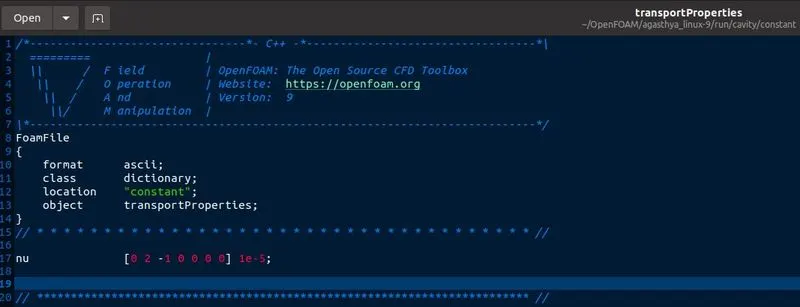
BlockMeshDict file for Grading Factor 1:
/*--------------------------------*- C++ -*----------------------------------*\
  =========                 |
  \\      /  F ield         | OpenFOAM: The Open Source CFD Toolbox
   \\    /   O peration     | Website:  https://openfoam.org
    \\  /    A nd           | Version:  9
     \\/     M anipulation  |
\*---------------------------------------------------------------------------*/
FoamFile
{
    format      ascii;
    class       dictionary;
    object      blockMeshDict;
}
// * * * * * * * * * * * * * * * * * * * * * * * * * * * * * * * * * * * * * //

convertToMeters 0.01;

vertices
(
    (0 0 0) //vertex 0
    (8 0 0) //vertex 1
    (8 0.5 0) //vertex 2
    (0 0.5 0) //vertex 3
    (8 1 0) //vertex 4
    (0 1 0) //vertex 5
    (20 1 0) //vertex 6
    (20 0.5 0) //vertex 7
    (20 0 0) //vertex 8
    (20 -1 0) //vertex 9
    (8 -1 0) //vertex 10
    (0 0 1) //vertex 11
    (8 0 1) //vertex 12
    (8 0.5 1) //vertex 13
    (0 0.5 1) //vertex 14
    (8 1 1) //vertex 15
    (0 1 1) //vertex 16
    (20 1 1) //vertex 17
    (20 0.5 1) //vertex 18
    (20 0 1) //vertex 19
    (20 -1 1) //vertex 20
    (8 -1 1) //vertex 21
);

blocks
(
    hex (0 1 2 3 11 12 13 14) (50 5 1) simpleGrading (1 1 1)
    hex (3 2 4 5 14 13 15 16) (50 5 1) simpleGrading (1 1 1)
    hex (2 7 6 4 13 18 17 15) (150 5 1) simpleGrading (1 1 1)
    hex (1 8 7 2 12 13 18 13) (150 5 1) simpleGrading (1 1 1)
    hex (10 9 8 1 21 20 19 12) (150 5 1) simpleGrading (1 1 1)
);

edges
(
);

boundary
(
    inlet
    {
        type patch;
        faces
        (
            (0 11 14 3)
            (3 14 16 5)
        );
    }
    outlet
    {
        type patch;
        faces
        (
            (9 8 19 20)
            (8 7 18 19)
            (7 6 17 18)
        );
    }
    walls
    {
        type wall;
        faces
        (
            (4 5 16 15)
            (6 4 15 17)
            (0 1 12 11)
            (10 9 20 21)
            (10 21 12 1)
        );
    }
);

mergePatchPairs
(
);

// ************************************************************************* //
Meshing done with Grading Factor 1:
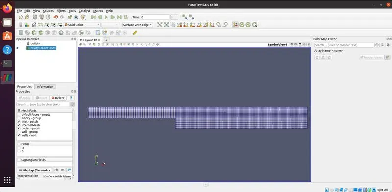
Velocity U throughout the geometry at initial and final timesteps: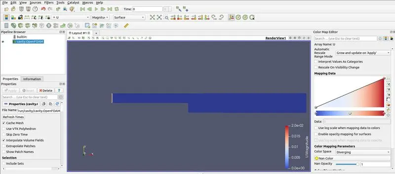
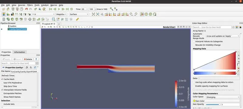
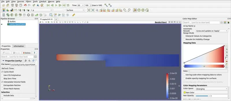
Pressure p throughout the geometry at initial and final timesteps: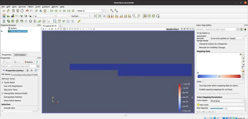
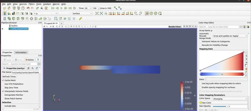
Velocity profile at 0.085m from the inlet: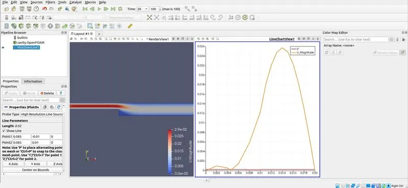
BlockMeshDict file for Grading Factor 0.2:
/*--------------------------------*- C++ -*----------------------------------*\
  =========                 |
  \\      /  F ield         | OpenFOAM: The Open Source CFD Toolbox
   \\    /   O peration     | Website:  https://openfoam.org
    \\  /    A nd           | Version:  9
     \\/     M anipulation  |
\*---------------------------------------------------------------------------*/
FoamFile
{
    format      ascii;
    class       dictionary;
    object      blockMeshDict;
}
// * * * * * * * * * * * * * * * * * * * * * * * * * * * * * * * * * * * * * //

convertToMeters 0.01;

vertices
(
    (0 0 0) //vertex 0
    (8 0 0) //vertex 1
    (8 0.5 0) //vertex 2
    (0 0.5 0) //vertex 3
    (8 1 0) //vertex 4
    (0 1 0) //vertex 5
    (20 1 0) //vertex 6
    (20 0.5 0) //vertex 7
    (20 0 0) //vertex 8
    (20 -1 0) //vertex 9
    (8 -1 0) //vertex 10
    (0 0 1) //vertex 11
    (8 0 1) //vertex 12
    (8 0.5 1) //vertex 13
    (0 0.5 1) //vertex 14
    (8 1 1) //vertex 15
    (0 1 1) //vertex 16
    (20 1 1) //vertex 17
    (20 0.5 1) //vertex 18
    (20 0 1) //vertex 19
    (20 -1 1) //vertex 20
    (8 -1 1) //vertex 21
);

blocks
(
    hex (0 1 2 3 11 12 13 14) (50 5 1) simpleGrading (1 5 1)
    hex (3 2 4 5 14 13 15 16) (50 5 1) simpleGrading (1 0.2 1)
    hex (2 7 6 4 13 18 17 15) (150 5 1) simpleGrading (5 0.2 1)
    hex (1 8 7 2 12 13 18 13) (150 5 1) simpleGrading (5 5 1)
    hex (10 9 8 1 21 20 19 12) (150 5 1) simpleGrading (5 5 1)
);

edges
(
);

boundary
(
    inlet
    {
        type patch;
        faces
        (
            (0 11 14 3)
            (3 14 16 5)
        );
    }
    outlet
    {
        type patch;
        faces
        (
            (9 8 19 20)
            (8 7 18 19)
            (7 6 17 18)
        );
    }
    walls
    {
        type wall;
        faces
        (
            (4 5 16 15)
            (6 4 15 17)
            (0 1 12 11)
            (10 9 20 21)
            (10 21 12 1)
        );
    }
);

mergePatchPairs
(
);

// ************************************************************************* //
Meshing done with Grading Factor 0.2: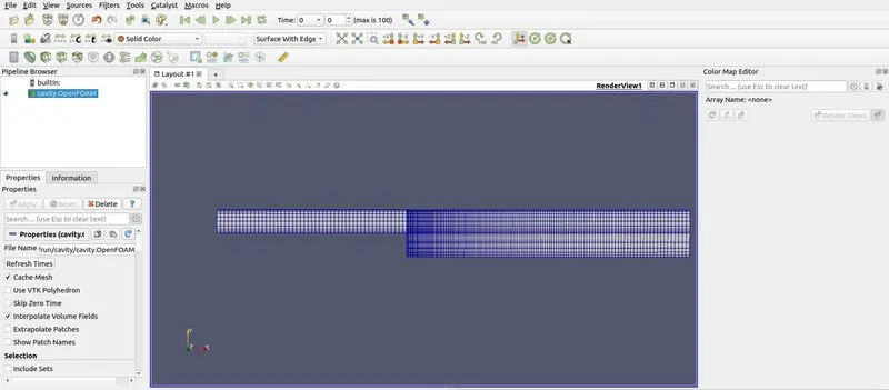
Velocity U throughout the geometry at initial and final timesteps: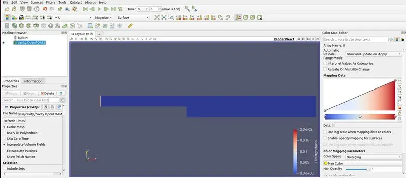
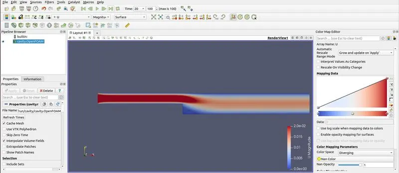
Pressure p throughout the geometry at initial and final timesteps: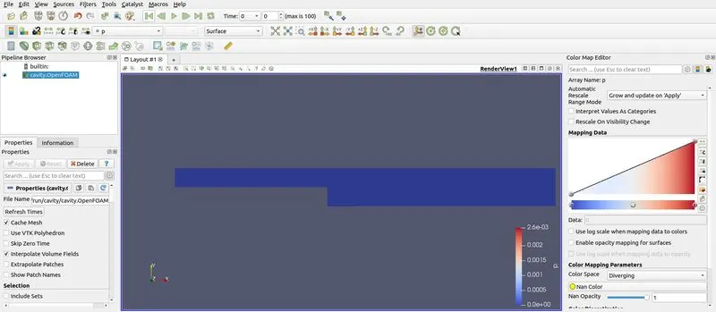
Velocity profile at 0.085m from the inlet: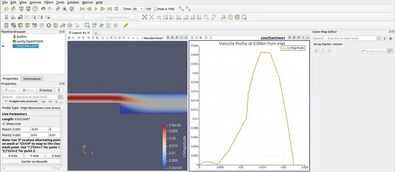
INFERENCES:
Incompressible laminar viscous flow has been simulated through a Backward Facing Step Geometry as required using Grading Factor 1, 0.2. Velocity profile has been measured and plotted at 0.085m from the inlet section in both cases.
The Grading Factor can be defined as the ratio of the last cell size to first cell size. While the grading factor does not adversely affect the solution of the problem, having a smaller grading factor can increase the accuracy. This is due to having smaller gridsize at critical sections of the geometry. Also, this will increase the efficiency of the program as it does not imply a very small gridsize for the entire geometry, only for the critical sections of the geometry. Thus, we also observe that by the usage of a smaller grading factor, the mesh becomes more smoother and we get a much neater curve in lesser time and computational requirements.