Simulation of a backward facing step in OpenFOAM
Introduction
Generally, the movement of fluid liquid or gas is referred to as flow. That concept describes the fluid behaviour and interactions with its surrounding environment. However, flow can be either laminar or turbulent. Thus, in this project, we performed the simulation of an incompressible laminar viscous flow across a sudden steep expansion in area and we studied the boundary layer separation phenomena using OpenFOAM in the Linux environment.
Objectives
Though the main objective of this project is to analyse and simulate this classical CFD benchmarking problem, there are key points to achieve:
- Generating proper grading and mesh connectivity
- Performing 2 case studies:
Simulate the flow without using any grading factor
Simulate the flow with grading factor of 0.2
- Determine the velocity profile at 0.085 m from the inlet of the geometry for both case studies and compare
- Understand and explain how the properties such as velocity and pressure behave
- Understand and explain the importance of grading factor in meshing and how it affects the results.
Methodology
In order to achieve all the objectives listed above, several steps are involved. The first step is about choosing the right solver followed by the selection of the solver tutorial to create the geometry as shown below. Once the geometry is created, we proceed to create the mesh according to the given specifications.
After that, we set up the case by assigning the initial and boundary conditions. Then, the results are post-processed and required plots are done.
However, we have to know how each step is carried out in detail.
- How the solver is chosen?
Taking a look at the key points of the problem which is to be solved, some assumptions are made:
- The fluid is Newtonian
- The flow is incompressible and laminar which implies a low Reynolds number
- The fluid flows without any frictional losses
Considering all these assumptions, the corresponding solver is icoFoam. Indeed, icoFoam solves the incompressible laminar Navier-Stokes equations using the PISO algorithm. The code is inherently transient, requiring initial and boundary conditions.
- How the solver tutorial is chosen?
Inside the icoFoam, the solver tutorial called cavity is selected. This tutorial is then copied into $FOAM_RUN folder and then we proceed to the modification of its geometry and initial conditions according to our problem statement.
- How the geometry is created?
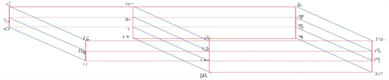
One special thing about OpenFOAM is that the geometry is created in blocks. So, to create our geometry, the dictionary file namely blockMeshDict is used. The required geometry is created following the sketch below by indexing different vertices and defining different faces.
The settings for mesh generation are also done in the same file. The mesh specifications are as follows:
- The number of cells along the x direction (longer dimension) = 200
- The number of cells along the longer y direction = 20
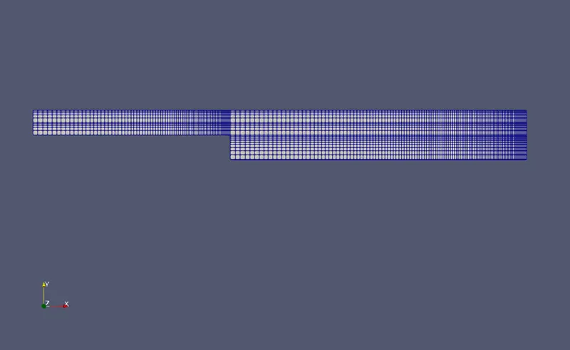
- The grading factor used is 0.2 and the results are compared
The mesh is then generated using the single mesh generator blockMesh in OpenFOAM.
- How the case is set?
To finalise the case setting, the boundary conditions as well as wall conditions are assigned in the blockMeshDict file; the time step and the end time is set in ControlDict file and different initial conditions for velocity and pressure properties are also set using velocity and pressure files respectively.
All this is shown below in the results post-proceesing section.
- Post-Processing Results:
As states above, the simulations are run for two cases as per change in grading factor. The results are post processed using ParaView from paraFoam.
- Without grading factor (GF=1)
Boundary & Wall conditions:
/*--------------------------------*- C++ -*----------------------------------*
  =========                 |
  \      /  F ield         | OpenFOAM: The Open Source CFD Toolbox
   \    /   O peration     | Website:  https://openfoam.org
    \  /    A nd           | Version:  9
     \/     M anipulation  |
*---------------------------------------------------------------------------*/
FoamFile
{
    format      ascii;
    class       dictionary;
    object      blockMeshDict;
}
// * * * * * * * * * * * * * * * * * * * * * * * * * * * * * * * * * * * * * //

convertToMeters 0.001;

vertices
(
    (0 0 0)
    (80 0 0)
    (80 5 0)
    (0 5 0)
    (0 0 1)
    (80 0 1)
    (80 5 1)
    (0 5 1)
    (200 0 0)
    (200 5 0)
    (200 0 1)
    (200 5 1)
    (80 -10 0)
    (200 -10 0)
    (80 -10 1)
    (200 -10 1)
    (200 10 0)
    (80 10 0)
    (200 10 1)
    (80 10 1)
    (0 10 0)
    (0 10 1)

);

blocks
(
    hex (0 1 2 3 4 5 6 7) (80 5 1) simpleGrading (1 1 1)
    hex (1 8 9 2 5 10 11 6) (120 5 1) simpleGrading (1 1 1)
    hex (12 13 8 1 14 15 10 5) (120 10 1) simpleGrading (1 1 1)
    hex (2 9 16 17 6 11 18 19) (120 5 1) simpleGrading (1 1 1)
    hex (3 2 17 20 7 6 19 21) (80 5 1) simpleGrading (1 1 1)

);

edges
(
);

boundary
(
 inlet
    {
        type patch;
        faces
        (
            (0 4 7 3)
            (3 7 21 20)
        );
    }
    outlet
    {
        type patch;
        faces
        (
            (13 8 10 15)
            (8 9 11 10)
            (9 16 18 11)
        );
    }
    noSlipWall
    {
        type wall;
        faces
        (
            (17 20 21 19)
            (16 17 19 18)
            (0 1 5 4)
            (1 12 14 5)
            (12 13 15 14)

        );
    }
    frontAndBack
    {
        type empty;
        faces
        (
            (0 3 2 1)
            (3 20 17 2)
            (2 17 16 9)
            (1 2 9 8)
            (12 1 8 13)
            (4 5 6 7)
            (7 6 19 21)
            (6 11 18 19)
            (5 10 11 6)
            (14 15 10 5)
        );
    }
);

);

mergePatchPairs
(
);

// ************************************************************************* //
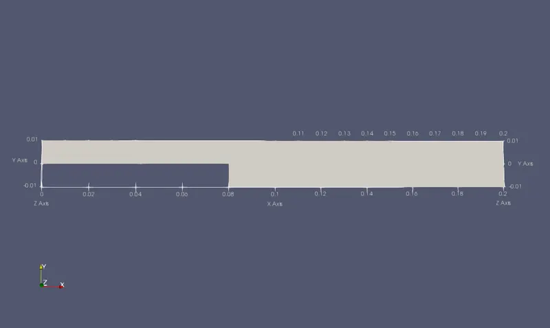
The obtained geometry is as shown:
ControlDict file:
/*--------------------------------*- C++ -*----------------------------------*
  =========                 |
  \      /  F ield         | OpenFOAM: The Open Source CFD Toolbox
   \    /   O peration     | Website:  https://openfoam.org
    \  /    A nd           | Version:  9
     \/     M anipulation  |
*---------------------------------------------------------------------------*/
FoamFile
{
    format      ascii;
    class       dictionary;
    location    "system";
    object      controlDict;
}
// * * * * * * * * * * * * * * * * * * * * * * * * * * * * * * * * * * * * * //

application     icoFoam;

startFrom       startTime;

startTime       0;

stopAt          endTime;

endTime         0.5;

deltaT          0.0005;

writeControl    timeStep;

writeInterval   200;

purgeWrite      0;

writeFormat     ascii;

writePrecision  6;

writeCompression off;

timeFormat      general;

timePrecision   6;

runTimeModifiable true;


// ************************************************************************* //
In the above file, we can see that :
- The starting time = 0
- The time step deltaT = 0.0005
- The end time endTime = 0.5 s
Initial conditions:
For velocity
/*--------------------------------*- C++ -*----------------------------------*
  =========                 |
  \      /  F ield         | OpenFOAM: The Open Source CFD Toolbox
   \    /   O peration     | Website:  https://openfoam.org
    \  /    A nd           | Version:  9
     \/     M anipulation  |
*---------------------------------------------------------------------------*/
FoamFile
{
    format      ascii;
    class       volVectorField;
    object      U;
}
// * * * * * * * * * * * * * * * * * * * * * * * * * * * * * * * * * * * * * //

dimensions      [0 1 -1 0 0 0 0];

internalField   uniform (0 0 0);

boundaryField
{
    inlet

    {
        type            fixedValue;
        value           uniform (1 0 0);

    }

    outlet
    {
        type            zeroGradient;

    }

    noSlipWall
    {
        type            noSlip;
    }


    frontAndBack
    {
        type            empty;
    }
}

// ************************************************************************* //
For pressure
/*--------------------------------*- C++ -*----------------------------------*
  =========                 |
  \      /  F ield         | OpenFOAM: The Open Source CFD Toolbox
   \    /   O peration     | Website:  https://openfoam.org
    \  /    A nd           | Version:  9
     \/     M anipulation  |
*---------------------------------------------------------------------------*/
FoamFile
{
    format      ascii;
    class       volScalarField;
    object      p;
}
// * * * * * * * * * * * * * * * * * * * * * * * * * * * * * * * * * * * * * //

dimensions      [0 2 -2 0 0 0 0];

internalField   uniform 0;

boundaryField
{
    inlet

    {
        type            zeroGradient;
    }

    outlet
    {
        type            fixedValue;
        value           uniform 0;

    }

    noSlipWall
    {
        type            zeroGradient;
    }


    frontAndBack
    {
        type            empty;
    }
}

// ************************************************************************* //
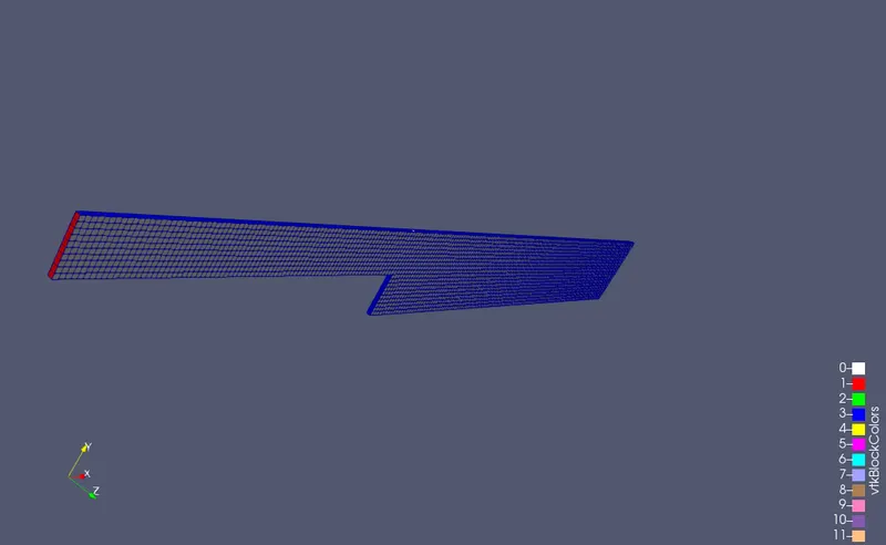
Mesh appearance
Velocity Property
- With Mesh
- Without Mesh
Pressure Property
- For grading factor 0.2
In this case, all the parameters are same as in the first case exept the grading factor which is now 0.2
- Mesh Appearance
Velocity Property
- with Mesh
- Without Mesh
Pressure Property
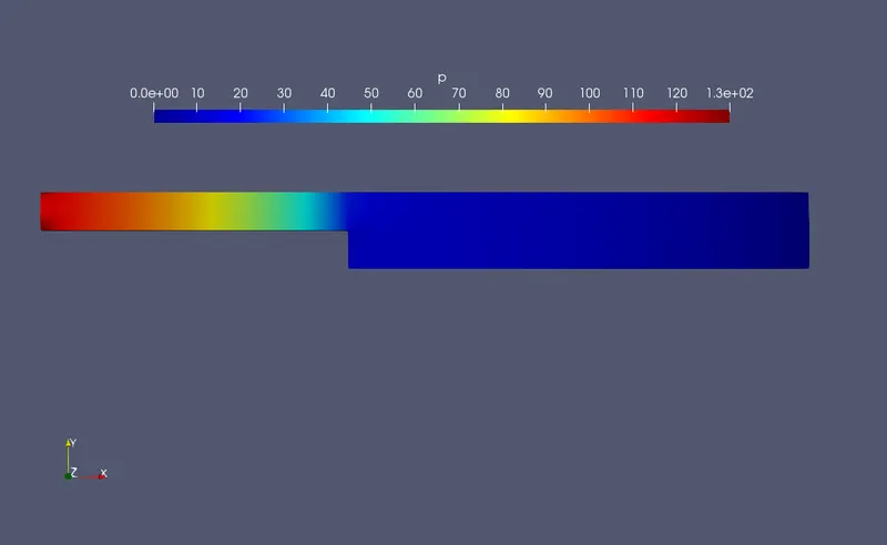
Results and comaprison of studied cases
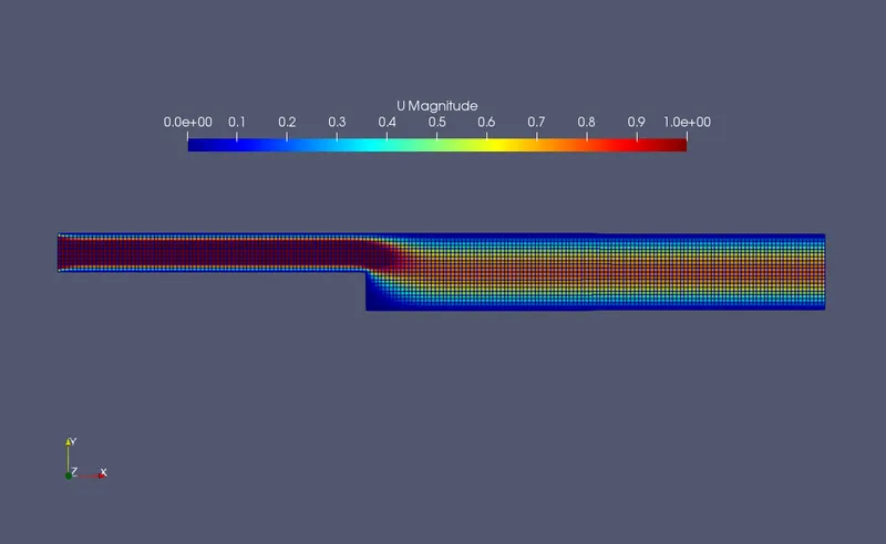
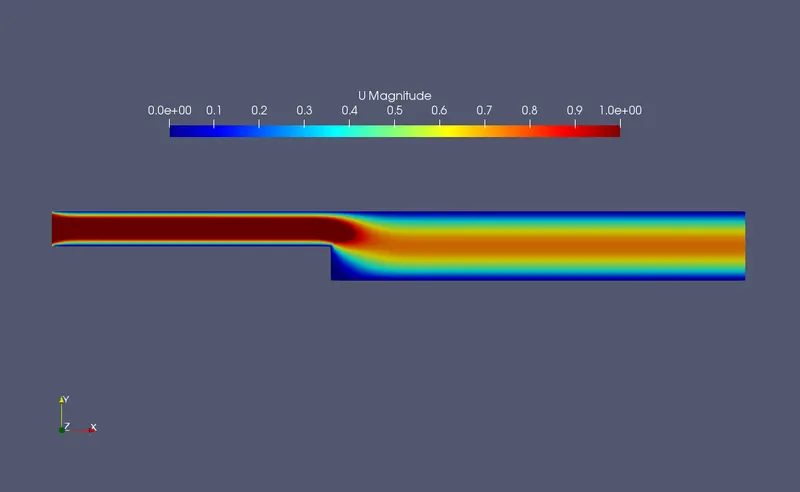
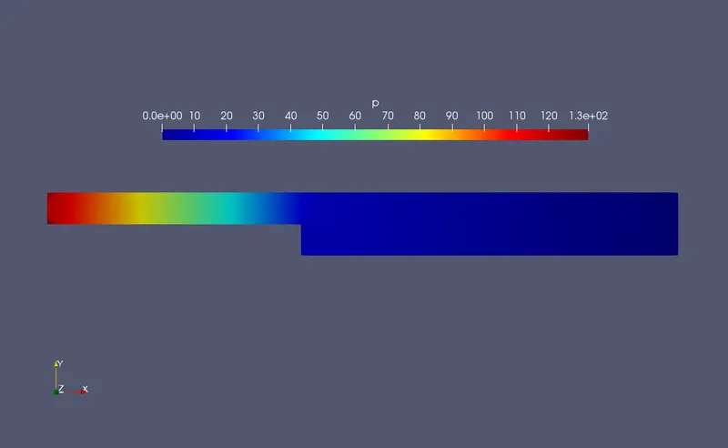
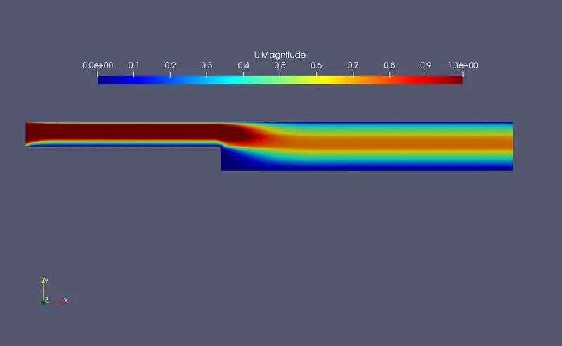
Taking a look to different contours, we can see that the flow gets detached from the wall at the steep level. There we can see that the pressure decreases drastically due to the change in the cross-sectional area. This change causes the flow to recirculate.
A comparative view of the contours for both mesh grading factors shows a slight change in the flow.
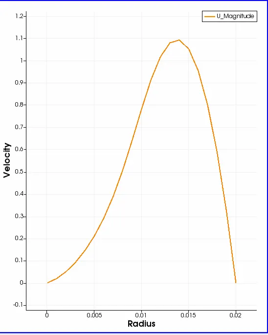
- CASE 1
- CASE 2
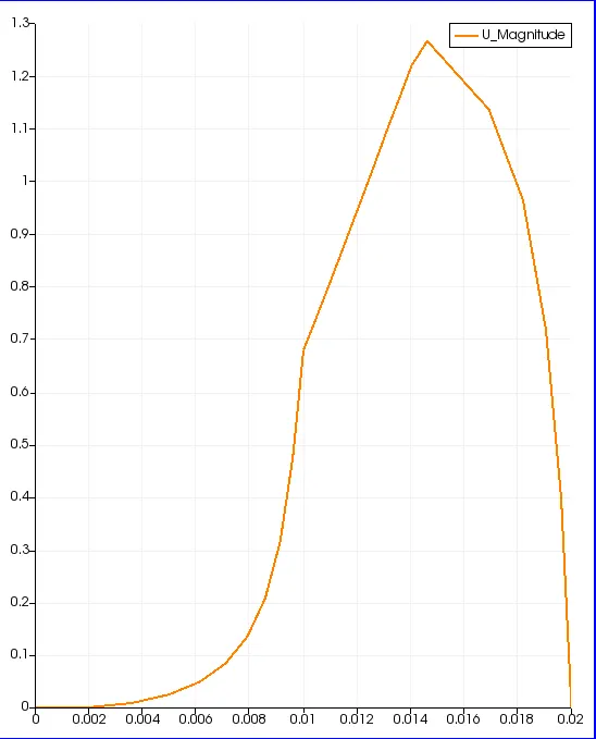
Now as per the comparison of the velocity profiles at x = 0.085 for both case studies, we can see that the profiles for both cases are closely parabolic in nature. By looking to these two graphs, we notice that the fluid velocity changes from zero at the wall because of the no-slip conditions to a maximum at the geometry’s centre. The slight difference is that the maximum velocity in the first case is around 1.1 m/s and in the second case where the mesh grading factor is 0.2, the maximum velocity is around 1.3 m/s. We can say that as the mesh gets finer, the results are slightly different from the coarser mesh.
CONCLUSION
To conclude, the velocity and pressure properties considered broadly give the similar results. However, when the mesh grading factor comes into play, better or finer results are observed. Thus, the accuracy of the expected solution gets increased.