Week 8 - Simulating Cyclone separator with Discrete Phase Modelling
Simulating Cyclone separator with Discrete Phase Modelling
Aim: To perform analysis on cyclone separator and calculate the separation efficiency and pressure drop.
- To write a few words about any four empirical models used to calculate the cyclone separator efficiency.
- To perform an analysis on a given cyclone separator model by varying the particle diameter from 1 μm to 5 μm and calculate the separation efficiency in each case. Discuss the results. [Use both the velocity's as 3m/sec.]
- To perform an analysis on a given cyclone separator model by varying the particle velocity from 1 m/sec to 5 m/sec and calculate the separation efficiency and pressure drop in each case. Discuss the results. [Use particle diameter size as 5 μm for all cases & keep flow velocity same as particle velocity]
Boundary Conditions:-
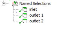
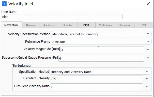
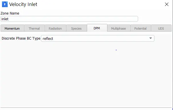
Inlet and wall:- Reflect
Outlet(Top):- Escape
Outlet(Bottom/dustbin) - Trap
Theory:
Cyclones are devices that employ a centrifugal force generated by a spinning gas stream to separate particles from the carrier gas. Their simple design, low maintenance costs, and adaptability to a wide range of operating conditions such as sizes and flow rates make cyclones one of the most widely used particle removal devices. By using suitable materials and methods of construction, cyclones may be adapted for use in extreme operating conditions: high temperature, high pressure, and corrosive gases. Cyclones are important particle removal devices in both engineering and process operations.
An inaccuracy in cyclone efficiency prediction may result in an inefficient design of cyclone separators. Models to predict the behaviour of cyclones are usually empirical. It remains largely a process of trial and error, since empirical cyclones models are only applicable to specific cyclone geometries.
CYCLONE EFFICIENCY EMPIRICAL MODELS:
1). IOZIA AND LEITH MODEL:
Iozia and Leith (1990) logistic model is a modified version of Barth (1956) model which is developed based on force balance. The model assumes that a particle carried by the vortex endures the influence of two forces: a centrifugal force and a flow resistance.
2). LI AND WANG MODEL:
The Li and Wang (1989) model includes particle bounce or re-entrainment and turbulent diffusion at the cyclone wall. A two-dimensional analytical expression of particle distribution in the cyclone is obtained.
3). KOCH AND LICHT MODEL:
Koch and Licht (1977) collection theory recognized the inherently turbulent nature of cyclones and the distribution of gas residence times within the cyclone.
4). LAPPLE MODEL:
Lapple (1951) model was developed based on force balance without considering the flow resistance. Lapple assumed that a particle entering the cyclone is evenly distributed across the inlet opening. The particle that travels from inlet half width to the wall in the cyclone is collected with 50% efficiency
Steps Followed:
a) Geometry preperation
b) Meshing
c) Setup
d) Results
a) Geometry preperation:
Import cyclone separator geometry into the spaceclaim.
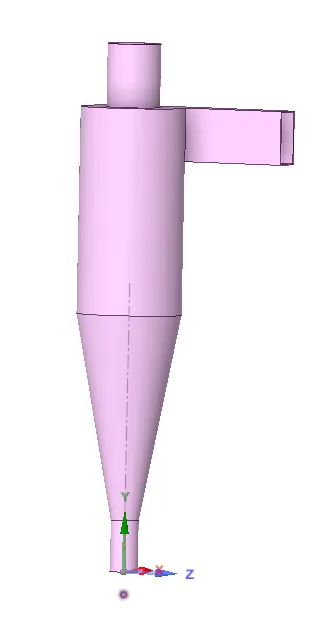
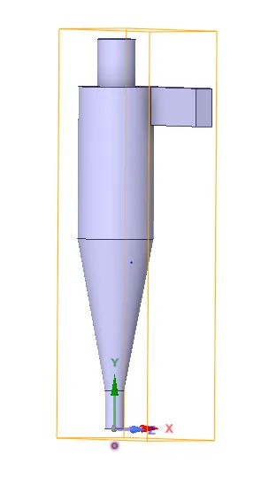
Extract the fluid volume using Volume Extract option.
Untick and suppress the solid volume.
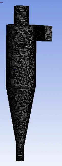
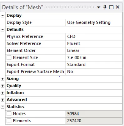
b) Meshing:
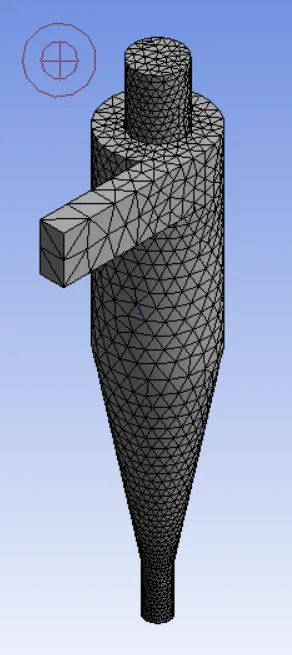
Basic Mesh:
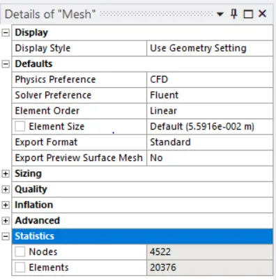
Refined Mesh:
Named Selections:
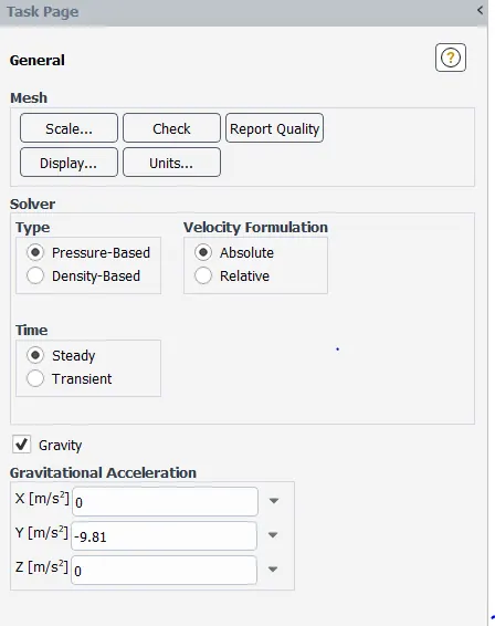
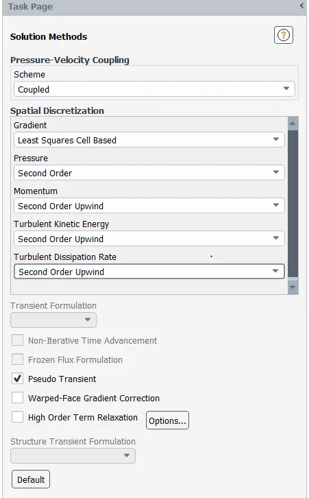
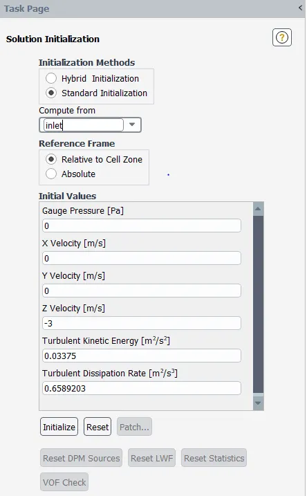
c) Setup:
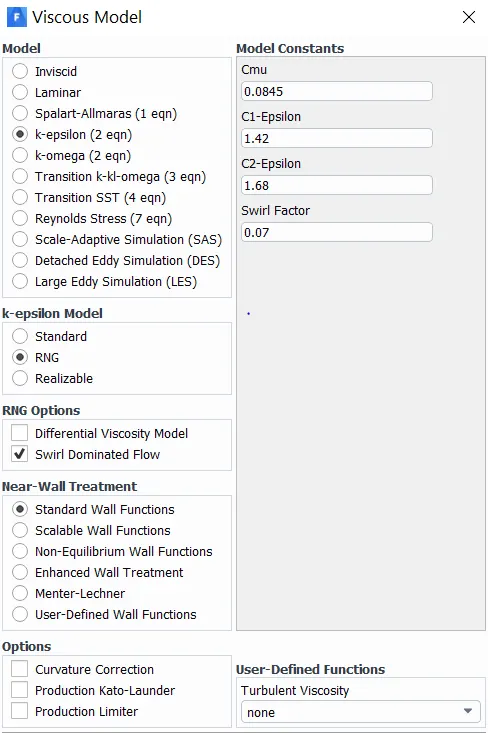
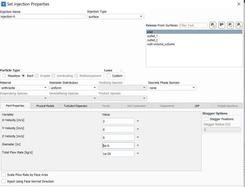
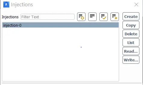
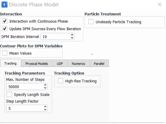
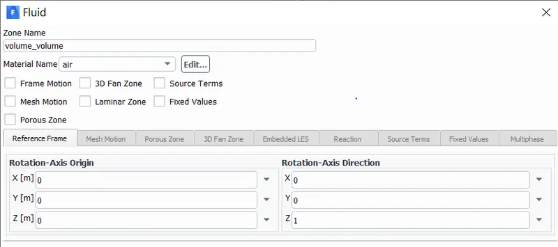
Cell zones:
Boundaries:
d) Results:
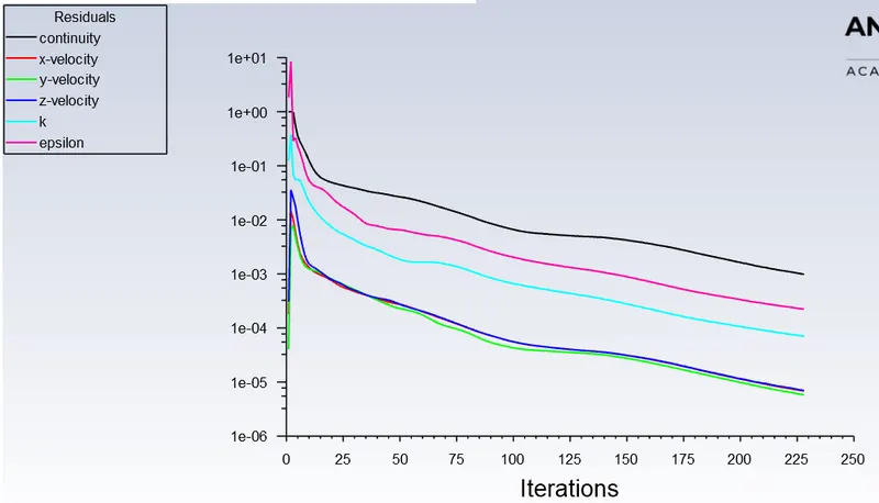
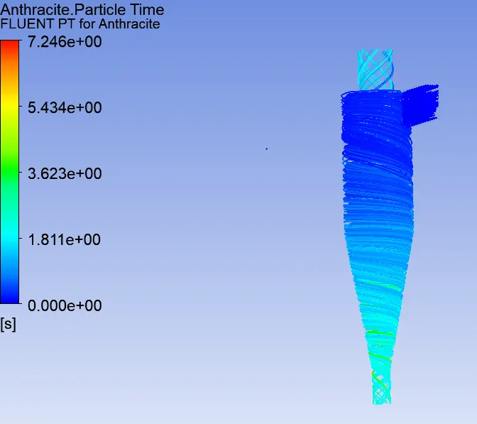
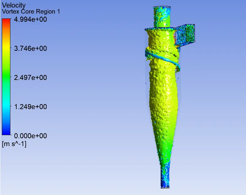
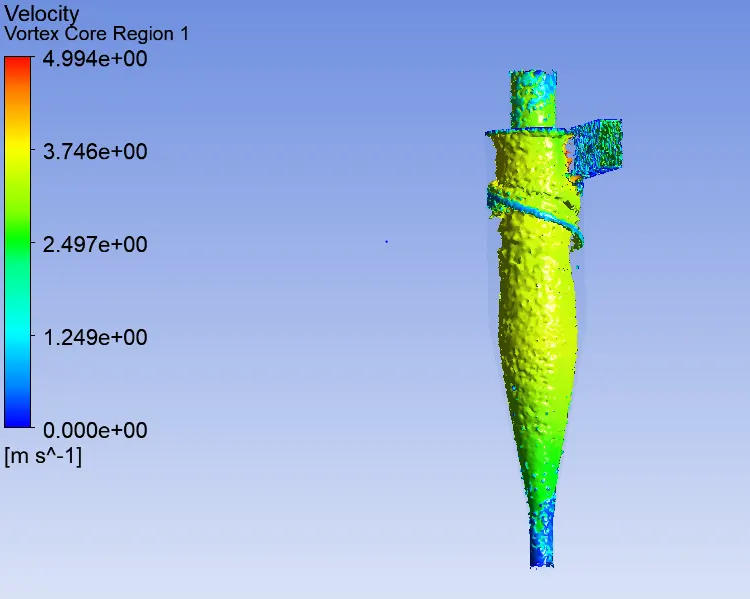
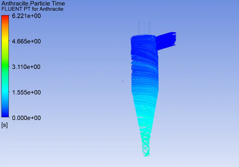
1). Analysis of a given cyclone separator model by varying the particle diameter from 1 μm to 5 μm and calculate the separation efficiency in each case. Discuss the results. [Use both the velocity's as 3m/sec]. The following results were obtained:
a). Particle diameter = 1 μm and inlet velocity = 3m/sec:
b). Particle diameter = 3 μm and inlet velocity = 3m/sec:
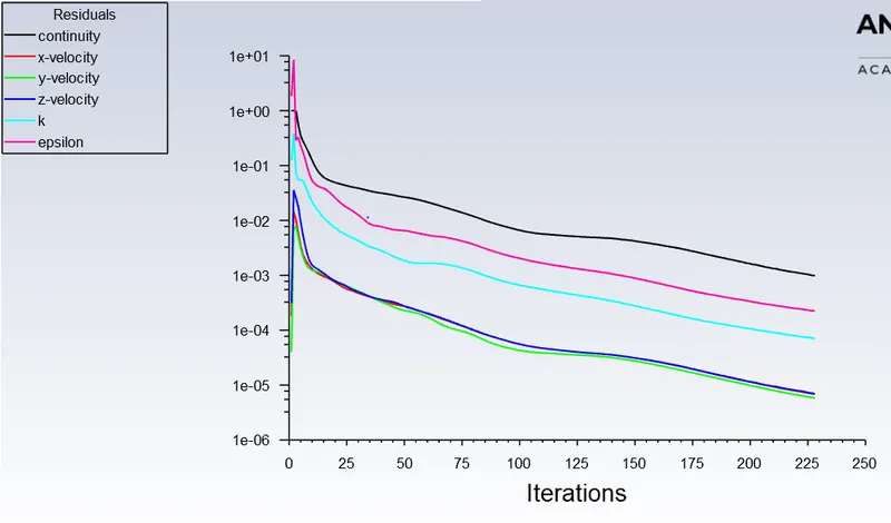
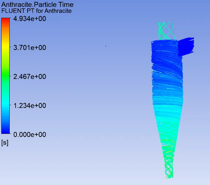
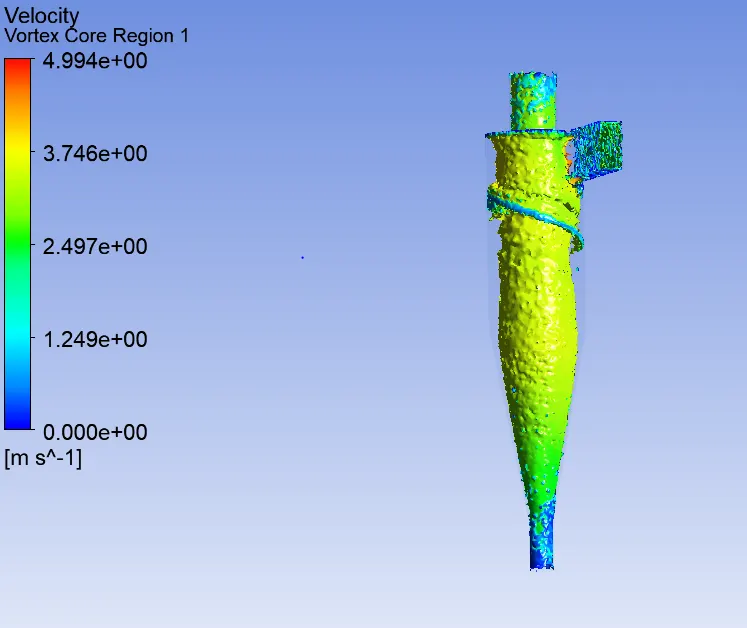
c). Particle diameter = 5 μm and inlet velocity = 3m/sec:
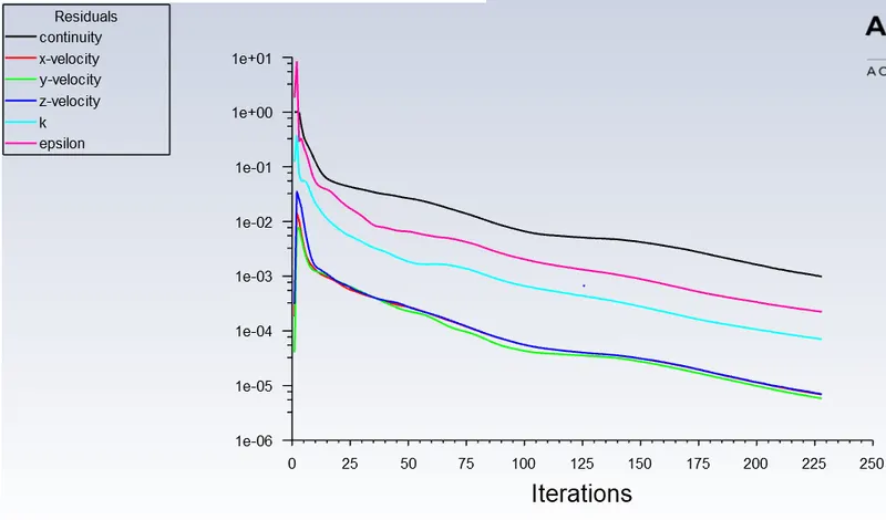
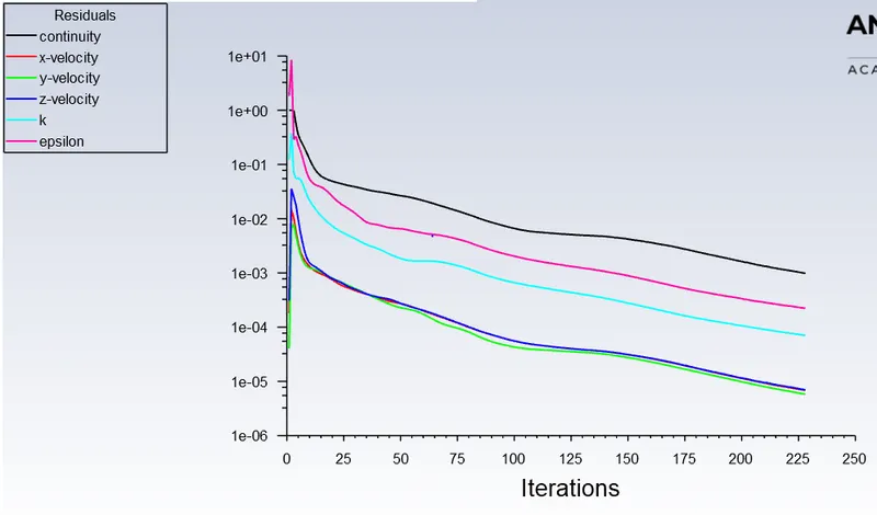
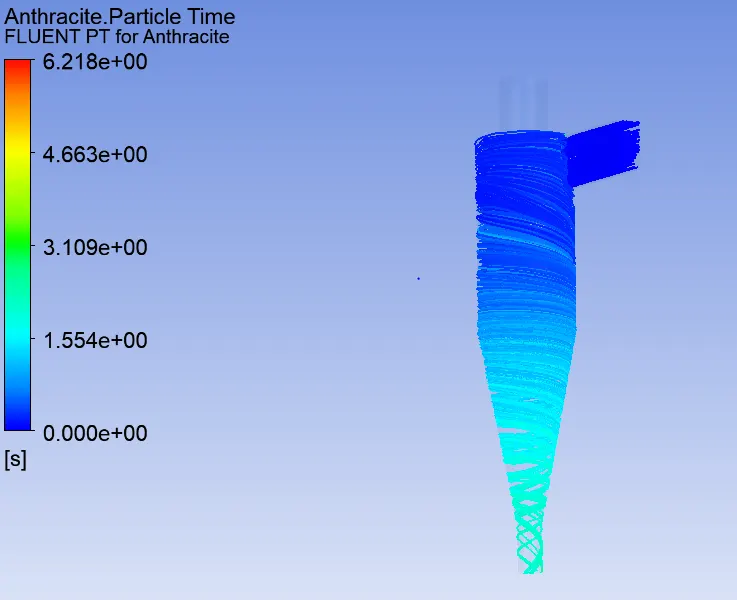
2). Analysis on a given cyclone separator model by varying the particle velocity from 1 m/sec to 5 m/sec and calculate the separation efficiency and pressure drop in each case. Discuss the results. [Use particle diameter size as 5 μm for all cases & keep flow velocity same as particle velocity]
a). Particle diameter = 5 μm and inlet velocity particles = 1m/sec, inlet velocity of air = 3m/sec:
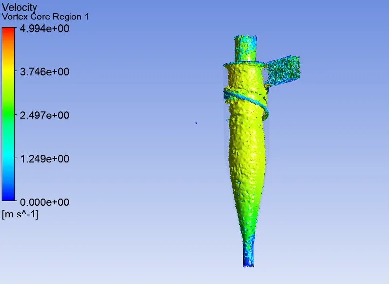
b). Particle diameter = 5 μm and inlet velocity particles = 3m/sec, inlet velocity of air = 3m/sec:
c). Particle diameter = 5 μm and inlet velocity particles = 5m/sec, inlet velocity of air = 3m/sec:
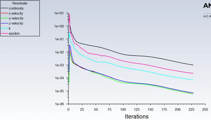
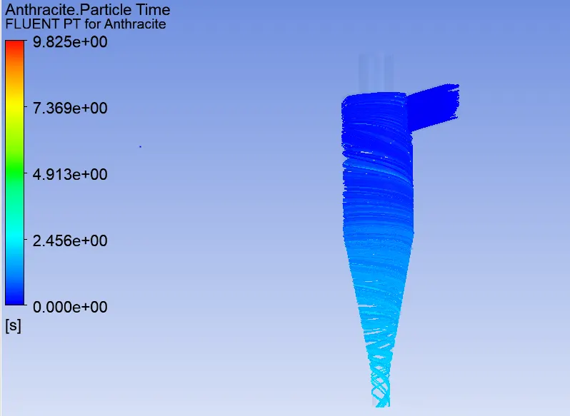
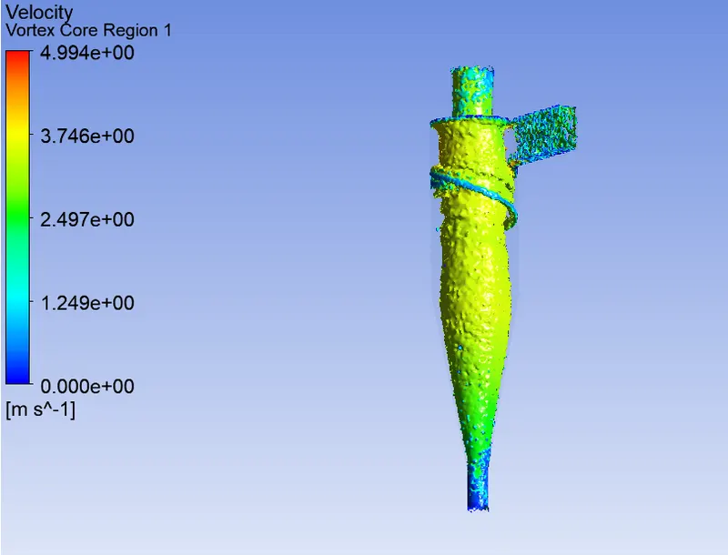
Following table is obtained for the efficiency and pressure drop:
| Velocity at inlet | particle diameter | Tracked | Escaped | Trapped | Incomplete | Inlet pressure | outlet-1 pressure | outlet-2 pressure | Efficiency | Pressure drop | |
| inlet velocity = 3m/sec | 3m/sec | 1μm | 226 | 49 | 42 | 135 | 21.6331 [Pa] | -0.00455887 [Pa] | 0 [Pa] | 0.185841 | 21.6331 [Pa] |
| 3m/sec | 3 μm | 226 | 27 | 187 | 12 | 21.6331 [Pa] | -0.00455887 [Pa] | 0 [Pa] | 0.827434 | 21.6331 [Pa] | |
| 3m/sec | 5 μm | 226 | 0 | 212 | 14 | 21.6331 [Pa] | -0.00455887 [Pa] | 0 [Pa] | 0.938053 | 21.6331 [Pa] | |
| Particle diameter = 5 μm | 1m/sec | 5 μm | 226 | 0 | 214 | 12 | 21.6331 [Pa] | -0.00455887 [Pa] | 0 [Pa] | 0.946903 | 21.6331 [Pa] |
| 3m/sec | 5 μm | 226 | 0 | 212 | 14 | 21.6331 [Pa] | -0.00455887 [Pa] | 0 [Pa] | 0.938053 | 21.6331 [Pa] | |
| 5m/sec | 5 μm | 226 | 0 | 207 | 19 | 21.6331 [Pa] | -0.00455887 [Pa] | 0 [Pa] | 0.915929 | 21.6331 [Pa] |
Comments:
1. For given inlet velocity, Efficiency decreases with particle diameter.
2. For the given particle size, the particle efficiency decreases with increase in inlet velocity.
3. Pressure drop remains constant, in almost all the cases.
Above behaviour of the cyclone separator is valid for the simulation parameters we have done the simulation. The efficiency and pressure drop also depends on geometry of the Cyclone Separator.
References: