Week 8 - Simulating Cyclone separator with Discrete Phase Modelling
Aim:- To perform analysis on cyclone separator and calculate the separation efficiency and pressure drop.
Objective:-
- To write a few words about any four empirical models used to calculate the cyclone separator efficiency.
- To perform an analysis on a given cyclone separator model by varying the particle diameter from 1 μm to 5 μm and calculate the separation efficiency in each case. Discuss the results. [Use both the velocity's as 3m/sec.]
- To perform an analysis on a given cyclone separator model by varying the particle velocity from 1 m/sec to 5 m/sec and calculate the separation efficiency and pressure drop in each case. Discuss the results. [Use particle diameter size as 5 μm for all cases & keep flow velocity same as particle velocity]
Introduction :-
Cyclonic separation is a method of removing particulates from an air, gas or liquid stream, without the use of filters, through vortex separation. When removing particulate matter from liquid, a hydrocyclone is used; while from gas, a gas cyclone is used. Rotational effects and gravity are used to separate mixtures of solids and fluids. The method can also be used to separate fine droplets of liquid from a gaseous stream.
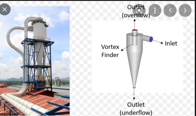
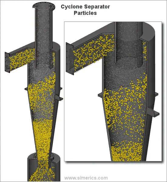
Gas containing entrained particles enters at high velocity through the tangential inlet at the top of the cyclone. The gas flows into the cyclone body/barrel at a tangent and begins to flow in a circular downward spiral towards the lower reject port, this downward flowing spiral is referred to as a spiral vortex.
The lighter components of this gas have less inertia, so it is easier for them to be influenced by the vortex and travel up it.Larger components of particulate matter have more inertia and are not as easily influenced by the vortex follows straight-line trajectory causing the high inertia particles to move out of the gas stream and impact with the cyclone separator body. These particles then fall to the base of the cyclone separator and out of the reject port. In this way, entrained particles of a certain size can be separated from the gas stream.
Here centripetal force that causes the particles to collide with the separator body.
There are several factors that can affect a cyclone separators efficiency. These include particle density, particle size, volumetric flow rate, pressure drop, cone length, body length, ratio of accept port to body diameter, and even the smoothness of the cyclone’s internal surfaces.
Empirical models on Cyclone separator efficiency :
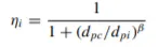
1) Iozia and Leith Model - based on force balance,this model assumes that a particle carried by the vortex endures the influence of two forces: a centrifugal force and a flow resistance. The collection efficiency (ηi) of particle diameter (dpi) can be calculated from
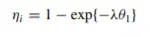
2) Li and Wang Model - includes particle bounce or reentrainment and turbulent diffusion at the cyclone wall. A two dimensional analytical expression of particle distribution in the cyclone is obtained.Based on certain assumptions the resultant expression of the collection efficiency for particle of any size is given as
3) Koch and Licht Mode - collection theory recognized the inherently turbulent nature of cyclones and the distribution of gas residence times within the cyclone. Koch and Licht described particle motion in the entry and collection regions with the additional assumptions.A force balance and an equation on the particles collection yields the grade efficiency as
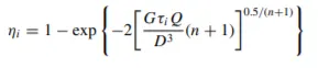
4) Lapple Model - was developed based on force balance without considering the flow resistance. Lapple assumed that a particle entering the cyclone is evenly distributed across the inlet opening. The particle that travels from inlet half width to the wall in the cyclone is collected with 50% efficiency.y. The semi empirical relationship developed by Lapple to calculate a 50% dpc is -
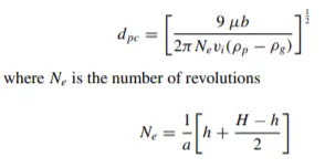
The efficiency of collection of any size of particle is given by - 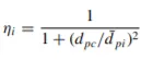
Solution & Modeling approach :
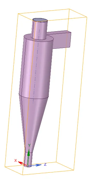
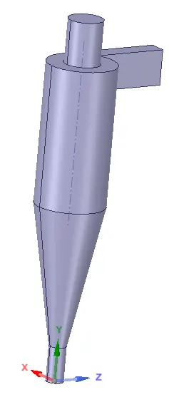
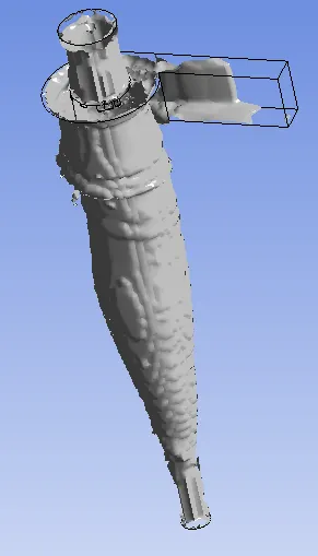
Geometry -
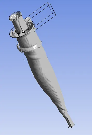
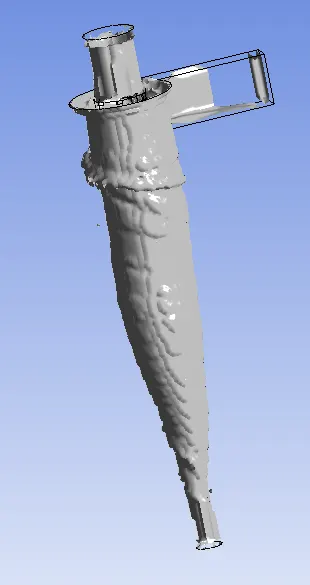
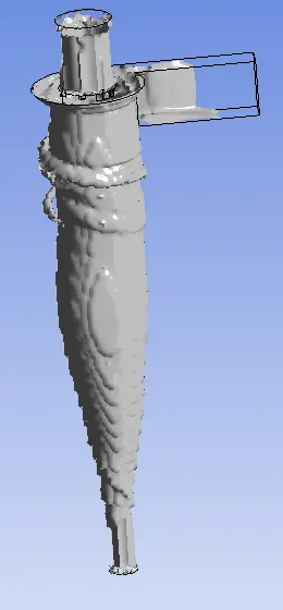
- Fluid volume is extracted by selecting the edges of Inlet & Outlets.
- Soild structure is supppresed for physics.
Mesh -
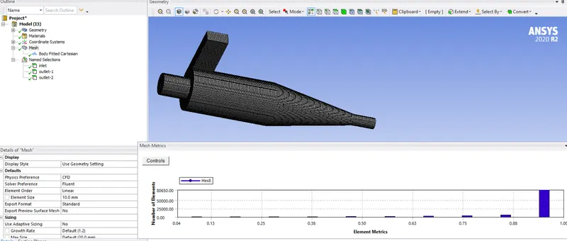
- Fine mesh size of 10mm global sizing is given.
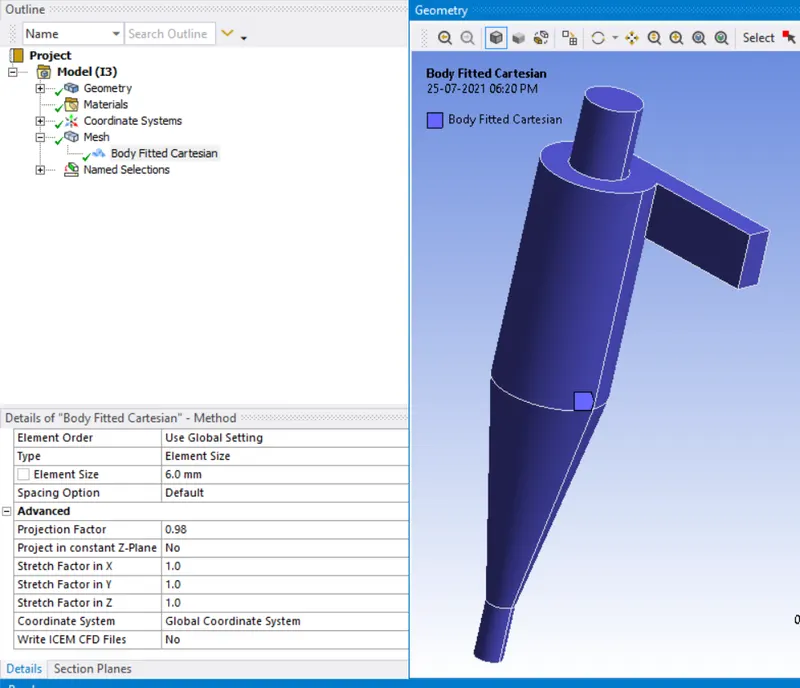
- In order to obtain unform meshing - Hexa mesh structure gives the best results and hence Cartesian method approach is adopted with size = 6mm.
No. of Elements = 93994 ; No. of Nodes = 104406
Setup -
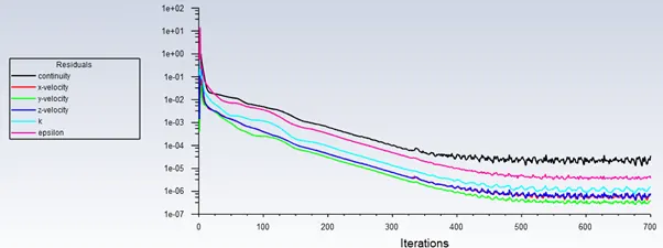
- Steady state analysis is performed. Gravity is employed in -Y direction.
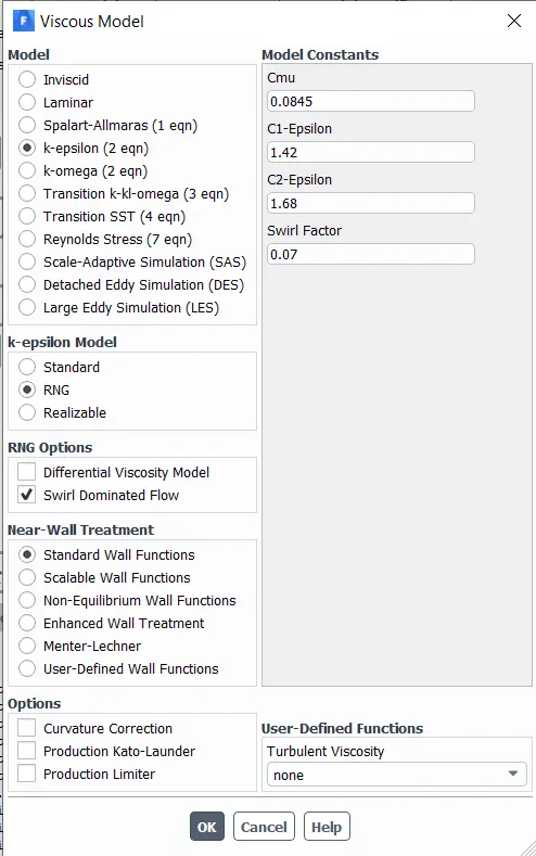
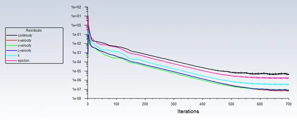
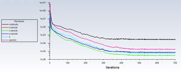
- K-epsilon RNG model is used, as it enhances the accuracy of swirling flows ad also 'Swirl Dominance' is enabled.
- DPM is turned On. DPM is computed in two ways -
Uncoupled flow - Does not have any Interaction with Continous phase
Coupled flow - Interaction & affects the flow of Continous phase (Mass, momentum & energy)
- Update DPM sources every flow iterations is optional for steady state analysis, eventhough enabled.
- DPM particle tracking interval is set to default - 10 iterations.
- Tracking parameters - Max. no. of time steps taken to track any single particle trajectory is limited to a set value, because this particles are trapped in re-circulation region and hence computing them will cause infinity. Default small step length factor is selected.
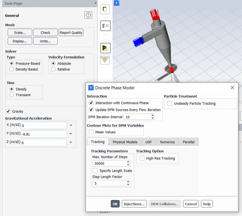
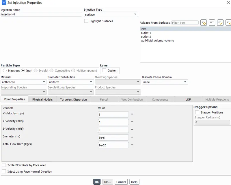
- Injection settings - Inert type particle called anthracite having uniform dia. is created for Discrete Injecting in surface (Inlet). Velocity Input is given in X-direction surface acting normal to Inlet.
- In practicel an High efficiency cyclone separator can filter out particles that are larger than 2.5 μm. Flow rate kept same default.
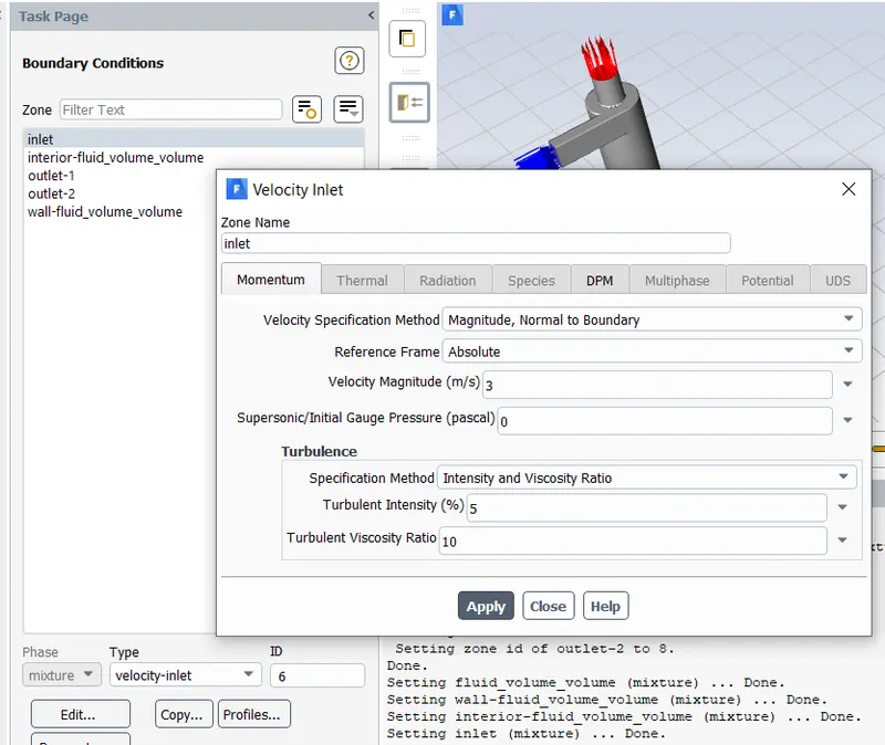
- Boundary condition - Velocity Inlet value for different cases is Input accordingly.
Discrete phase BC type :
Inlet & wall = Reflect
Outlet-1 top = Escape
Outlet-2 bottom = trap
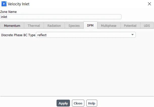
- In Solution method for Turbulent kinetic energy & disspation rate - Second order Upwind scheme is used, since they are more accurate spatial discrtization scheme for this sort of problem.
- Standard Intialization is computed from Inlet.
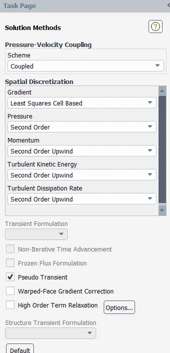
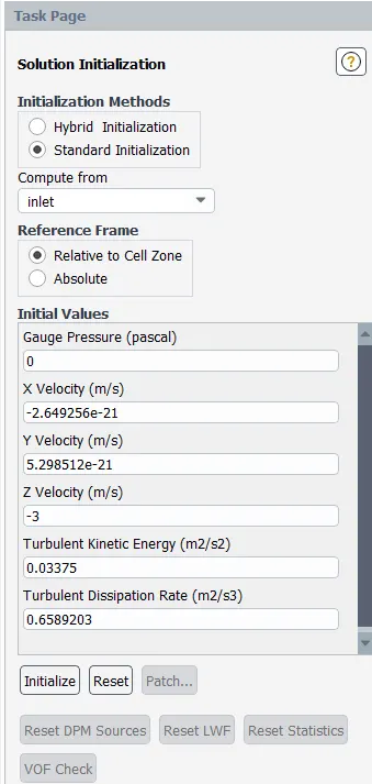
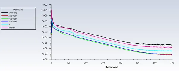
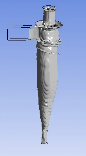
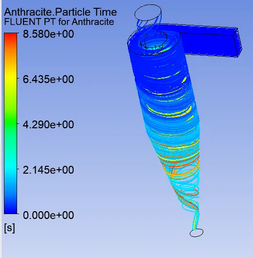
- After calculation is completed particle history data is Exported into a seperate directory file. Which is then Impoted in Post-processing to view the results.
Results -
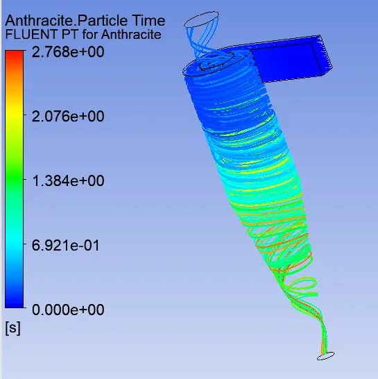
Case 1 - particle dia = 1μm , Velocity = 3m/sec
number tracked = 136, escaped = 28, trapped = 89, incomplete = 19

Case 2 - particle dia = 3μm , Velocity = 3m/sec
number tracked = 136, escaped = 14, trapped = 122
Case 3 - particle dia = 5μm , Velocity = 3m/sec
number tracked = 136, escaped = 16, trapped = 105, incomplete = 15
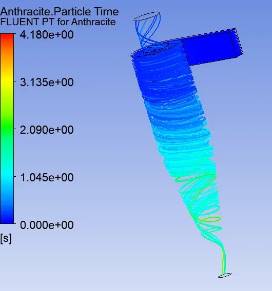
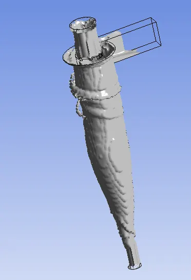
Case 4 - particle dia = 5μm , Velocity = 1m/sec
number tracked = 136, escaped = 19, trapped = 26, incomplete = 91
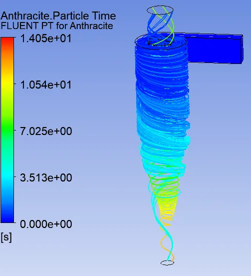
Case 5 - particle dia = 5μm , Velocity = 2m/sec
number tracked = 136, escaped = 13, trapped = 110, incomplete = 13
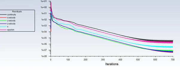
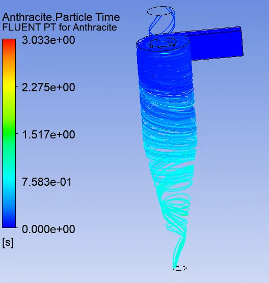
Case 6 - particle dia = 5μm , Velocity = 5m/sec
number tracked = 136, escaped = 14, trapped = 122
| cases | Particle size |
Inject velocity |
tracked | escaped | trapped | incomplete | Collector efficiency |
| 1 | 1 | 3 | 136 | 28 | 89 | 19 | 0.760684 |
| 2 | 3 | 3 | 136 | 14 | 122 | 0 | 0.897059 |
| 3 | 5 | 3 | 136 | 16 | 105 | 15 | 0.867769 |
| 4 | 5 | 1 | 136 | 19 | 26 | 91 | 0.577778 |
| 5 | 5 | 2 | 136 | 13 | 110 | 13 | 0.894309 |
| 6 | 5 | 5 | 136 | 14 | 122 | 0 | 0.897059 |
Comments :-
- When particle size reduced below 3μm efficiency reduced.
- At constant particle size & increasing Inject velocity efficiency increased.