Week 8 - Simulating Cyclone separator with Discrete Phase Modelling
Aim, Introduction, Theory:
To perform analysis on cyclone separator and calculate the separation efficiency and pressure drop. Cyclone separators are devies which can be used to separate particulate matter from gases by virtue of principle of inertia. In the device there is a constant supply of flue gases which needs to be filtered, by action of centrifugal forces i.e. the lighter air is separated and thrown out through an opening due to vortex formation. Cyclone separators have wide industrial applications where particulate sizes maybe very small like 2.5micrometers or 10micrometers but it cannot be applied for separtion of larger particle matter like aove 200 micrometer in size. The buttom part of the device is shaped in an inverted conical shape. The inverted conical shape makes it easier to collect the discarded matters to dispose off easily. The size of the device can be modified and changed according to necessity. Cyclone separators are useful in minimizing pollution.
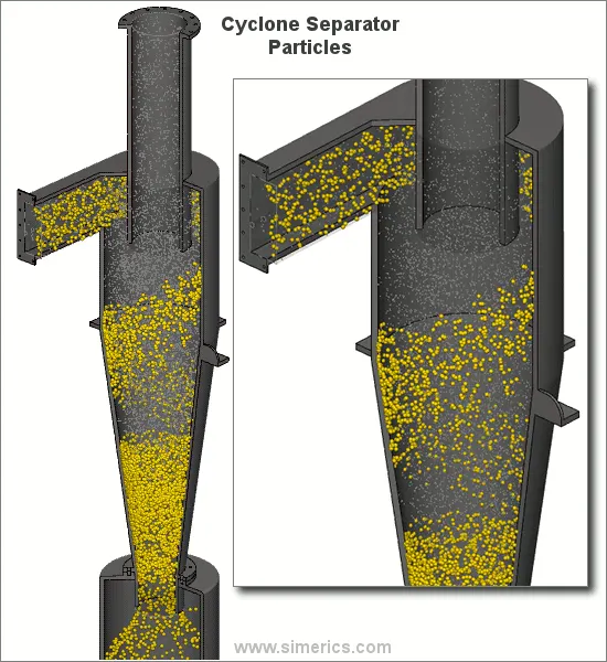 Animation.1- Cyclone separator
Solving and modelling approch:
To solve a cyclone separator problem on CFD we use something known as DPM (Discrete Phase Modelling). DPM is used when any one needs to design or understand behaviour of particles in a fluid flow inside a cyclone separator using the lagrangian method of particle tracking. The fluid flow volume is extracted from the geometry using volume extract by edge method. The face with rectangular shape is inlet the upper top is the air outlet and the buttom is for particulate matter to separate. Mesh is generated with element size of 10mm, solving with larger element size may result in limited particles that can be tracked.
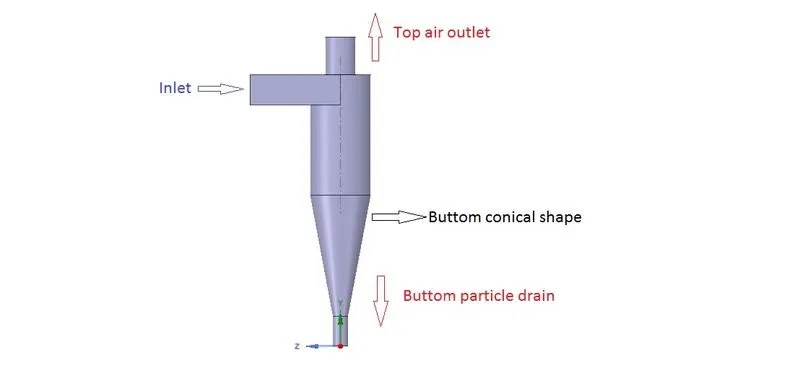
Fig.1- Geometry of cyclone separator
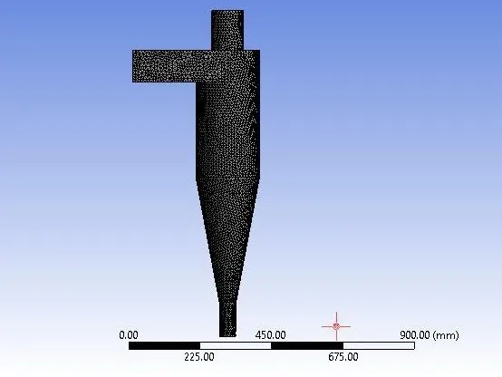
Fig.2- Mesh generated with element size of 10mm
Pre-processing and solver settings:
We use pressure-based, steady state solver. We will take into account the gavity forces acting along the negative y-axis. We have used k-epsilon<RNG
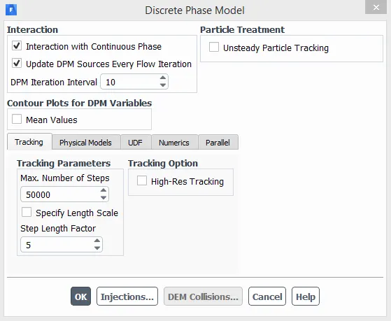
Fig.3- DPM settings
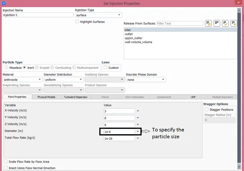
Fig.4- Injection settings to be used in solution
Boundary conditions are specified as
Inlet and wall:- Reflect
Outlet(Top):- Escape
Outlet(Bottom/dustbin) - Trap
For solution method we have choosen we have used second order upwind for kinetic energy and second order upwind for turbulent dissipaton rate to increase the efficiency of particle trajectories. We use standard initialization method to initialize the solution from the inlet.
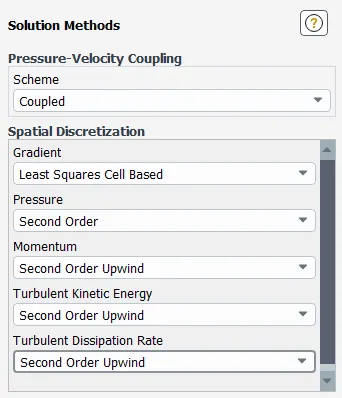
Fig.5- Solution method
Results:
| Particle size | Number tracked | Escaped | Trapped | Incomplete | Separation efficiency |
| 1e-6 | 124 | 24 | 42 | 58 | 33.870% |
| 2e-6 | 124 | 23 | 95 | 6 | 76.612% |
| 3e-6 | 124 | 19 | 105 | 0 | 84.647% |
| 4e-6 | 124 | 7 | 116 | 1 | 93.548% |
| 5e-6 | 124 | 0 | 124 | 0 | 100.00% |
Table.1- Particle History Data with different particle sizes
| Particle velocity | Number tracked | Escaped | Trapped | Incomplete | Separation fficiency | Pressure(pa) |
| 1m/s | 124 | 5 | 5 | 114 | 4.03% | 1.684 |
| 2m/s | 124 | 6 | 32 | 86 | 69.35% | 7.7100 |
| 3m/s | 124 | 0 | 124 | 0 | 100.00% | 17.9132 |
| 4m/s | 124 | 0 | 124 | 0 | 100.00% | 32.5289 |
| 5m/s | 124 | 0 | 124 | 0 | 100.00% | 51.6418 |
Table.2- Particle History Data with different particle velocity
Animation.1- Animation created using different particle sizes ranigng from 1micrometer to 5micrometer
The above animation has a compilation of different particle tracking where the particles vary from 1micrometer till 5micrometer. When played individually we can conclude that particle size with 5micrometer is most efficient as most or all of the particles are separated from the fluid flow. It is effective in separating particulate matter from flue gasses where the particle size is 5micrometer.
Animation.2- Particle tracking for varying particle speeds
The above animation has compilation of all the particle tracking with same particle size of 5micrometer but the particle speed is varying from 1m/s to 5m/s.
Conclusion:
In animation.2 we can see there is comparitively more number of particles flowing out through the upper outlet which we are supposed to control so that all the particulate matter or maybe most of the particulate matter falls in the particle collector placed below. The efficiency of the cyclone separator can be increased by varying the dimensions. When we look at the mass flow rates:
Mass Flow on inlet
0.006125 [kg s^-1]
Mass Flow on outlet
-0.00121202 [kg s^-1]
Mass Flow on upper_outlet
-0.00491256 [kg s^-1]
The mass flow rates can give understanding that the mass flowing from the upper outlet is lower than outlet at buttom because the cyclone separators are designed so.
FOUR MODELS USED TO CALCULATE CYCLONE SEPARATOR EFFICIENCY:
Iozia and Leith model-
The basic assumptions made in this model is there are two forces that may be acting on the vortex, those are centrifugal force and flow resistance. The Barth model of 1956is modified to develop this model where in Iozia and Leith added core diameter (Zc) and slope parameter (β).
`Zc=(H−S)−[(dcB)−1]` ford c>B
`Zc = H - S for dc < B`
`dc = 0.47 (ab/D^2)^-0.25 * (D`e/ D)^1.4`
The efficiency `eta`of particle diameter d(pi) is calculated as `eta i = 1/( 1+((dpc) /( dpi))^ β`
Li and Wang model-
Li and Wang model deals with particles that bounce re-enter and turbulent diffusion on the cyclone wall. A 2D analytical solution of particle distribution in the cyclone is obtained.
Li and Wang model had following assumptions made in the model:
- The radial particle velocity and radial concentration profile are not constant, for the uncollectd particulate matter in the cyclones.
- Turbulent diffusion coefficient and particle bounce are conidered on the boundary conditions where
c= c0, at θ = 0
Dr*del(c)/del(r) = (1-alpha)wc, at r= D/2
Koch and light model-
Koch and light model understood the turbulent nature of cyclones which are inherited and the distribution of gas residence time within the cyclone.
Koch and light model had following assumptions made in the model:
- The tangential velocity of particle and tangential of gas flow are equal
- The tangential velocity and radius of cyclone are related by `uR^n=constant`
Lapple model-
Lapple model was devloped without the considerations of flow resistance.
Lapple model has following assumption:
A particle entering the cyclone is evenly distributed across the inlet opening. The particle that travels half width to the wall from the inlet in the cyclone is collected with 50% efficiency.
Reference-EVALUATION ON EMPIRICAL MODELS FOR THE PREDICTION OF CYCLONE EFFICIENCY by Jolius Gimbun, T.G. Chuah2, Thomas S. Y. Choong and A. Fakhru’l-Razi