Ahmed Body Challenge
Aim: Simulating fluid flow around an Ahmed body to understand drag coefficient in automobiles.
Introduction: When designing any automobile Ahmed body helps in studying the drag coefficent in order to have an efficient and safe vehicle. Reducing the aerodynamic drag helps in increasing the motor efficiency there by reducing environment pollution. Keeping this is mind the aerodynamic drag should not be reduced so much so that the downward force is also reduced comparatively which may led to decrese in vehicle traction control leading to increased chances of road accidents.
Theory: Ahmed body was published by S.R Ahmed in his research "Some salient features of the time-averaged ground vehicle wake" in 1984. The geometrical shape had a lenght of 1.044m, height of 0.288m and width of 0.389m, has 0.5m cylindrical legs attached to the buttom of the body. The rear has a slant angle of 40 degree with the front side. The Ahmed body simulation is used in many automobile companies to study the drag in order to have a balance between efficiency and vehicle handling and control. When the drag is reduced drastically the downward forces also decreases. Ahmed body simulation is also used in validating simulation tools. Ahmed body has very simle geometry which corresponds to a car, it is helpful to study the Ahmed body with different materials and fluid flow direction.
Solving & Modelling approach: When trying to simulate flow around the Ahmed body we need to create a farfeild or domain which will enclose the Ahmed body in order to give opportunity to assign proper boundary conditions. We will use the ENCLOUSRE OPTION in in order to create a whole single volume. In order for us to have a analysis outside the Ahmed bosy only we need to use SUPRESS FOR PHYSICS OPTION to exclude the inner portrion of grid generation process, as we need only to simulate flow outside the Ahmed body. After doing a baseline mesh and simulation we have the idea that mesh needs to be refined. We need more grid points near the Ahmed body in contrast to the whole volume. For that we will draw another smaller box enclosing the Ahmed body in order to capture the physics in upstream and the wake region of the body, something known as LOCAL REFINEMENT. If generated mesh at this situation we can easily find out there are overlapping grid points in the local refinement region, we need to solve the overlapping issue with interference check. In order to make an uniform mesh we need to set SHARE TOPOLOGY to SHARE in the settings for geometry.
For meshing we will create HEXAHEDRON shapes for the outer region of the inside enclouse in order to improve our accuracy and make the mesh more uniform. We need to set the element size of the mesh so as to have a more refineded setup just outside the inner enclousre i.e make it more refined, where as have relatively bigger element size outside the enclosure. The cylindrical pillars of Ahmed body needs to be corrected with SIZING OPTION in order to have more cylindrical shape of the pillars. To capture the effects of fluid flow over the boundary we can create a boundary layer mesh by adding INFLATION LAYERS.
Pre-processing and solver setting: I am going to use a pressure based solver with k-omega turbulence model as I am more intrested in analysis of near the walls of the Ahmed body (based on previous readings and findings). I am not going to calculate the energy equations as the temperature is not being considered in the above case. I have a inlet velocity of 25 m/s and I am using the normal air as my fluid flow element as in real life we mostly deal with cars moving in air.
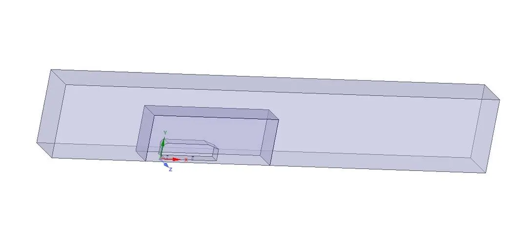
Fig.1- Geometry of the split Ahmed body
For meshing I have used an enclousre for the Ahemd body in that I have created a smaller enclousre to analyse the fluid flow near the car wall. I am using 100mm length of the element size for the outer enclousre and for the inner enclosure I have kept the element size as 50mm. I am more intrested in the analysis of the fluid flow just near the car wall so we do something known as local refinement of the mesh.
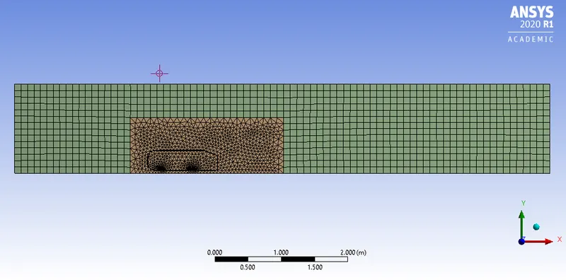
Fig.2- Local refinement and Mesh
Results:
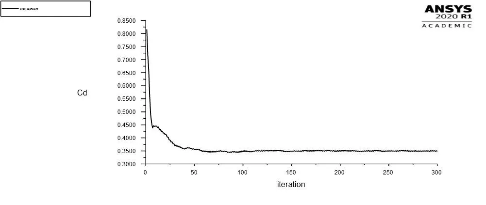
Fig.3- Coefficient of Drag
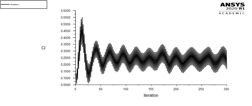
Fig.4- Coefficient of Lift
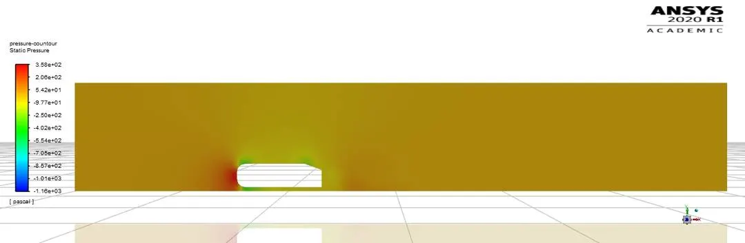
Fig.5- Pressure contour
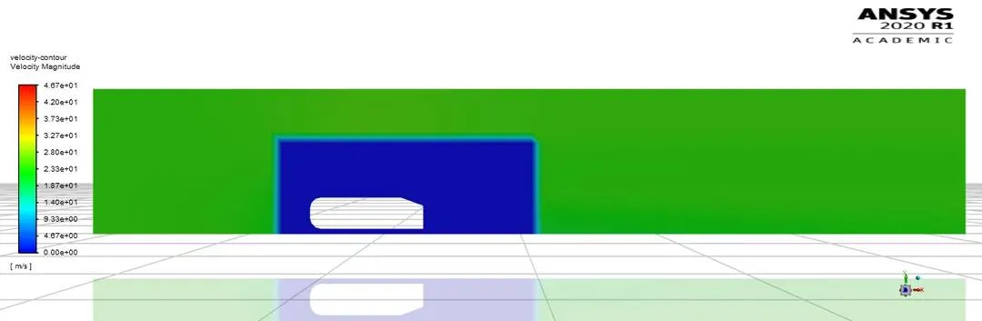
Fig.6- Velocity contour
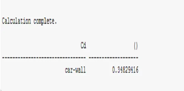
Fig.7- Coefficient of Drag for a refined case
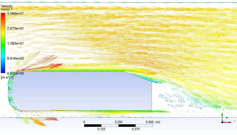
Fig.8- Vector plot showing the wake region
After changing the element sizes from 100mm to 80mm and 70mm we can check the grid dependency. For the above system of analysis the Cd for 100mm long element is 0.348294 and for 80 mm long element the Cd is 0.346161 and for a 70mm long element the Cd comes to be 0.344214. The Cd is not changing much with the change of grid sizes.
The reason for the negative pressure in the waker region is that the air pressure moves from high pressure to low pressure. Negative pressure created in wake region in helpful in the stability of cars to reduce the drag forces acting on a car body.