Week 6 - CHT Analysis on a Graphics card
The aim, Introduction, Theory:
To simulate flow around and inside graphics card. In many computers when the computational is very high or dealing with lots of graphics simultaneously works up the processor which in turn generates heat. The heat generated must be tackled with to operate the whole system in optimum level of temperature.
Every rotating part has some kind of energy which is transmitted in some form, in graphics card it is in the form of heat. Why is necessary to simulate the process, well first to lower the heat as it might decrease efficiency of the component. In most of the modern day computer we have graphics card present as a compenent and it is necessary to optimise the heat generated. In this simulation we simulate and study the heat genrated and the distribution of heat after. We use fins to decrease or distribute the heat generated through convection of processors.
Solving & Modelling approach:
In order to simulate the above phenomenon inside a graphics card, we have built a geometry which has very similar components of a real life graphics card and we can assign various material properties to the solid parts like the processsor and fins and bases to have a clear understanding of the heat generation and distribution inside it.
We create mesh for the geometry where we calculate the energy equations. Energy equations are calculated in order to monitor the heat generation. There are many components of a graphic card and to get correct interpolation we create conformal mesh around all the parts of the graphic card. We can do that by enabling share topology which creates conformal meshes.
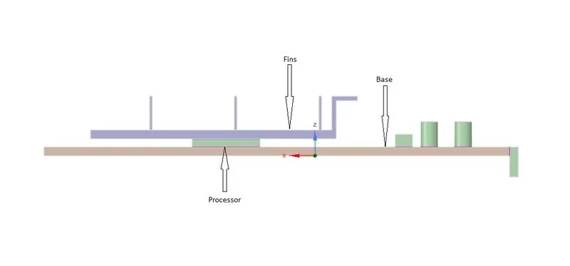
Fig.1- Inside geometry of graphics card with components
Pre-processing and solver setting:
The simulation is done with cell zone conditions assigned as solids for processor, fin, and the base. We do it mannualy in fluent. The energy equation are truned on to solve energy equations on each node. We use steady state solver with processor being made of steel, base with aluminum like material properties and the fins with nickel. We initialise the simulation with hybrid initialisation and create contours of temperature, most importantly on the processor, fin and base.
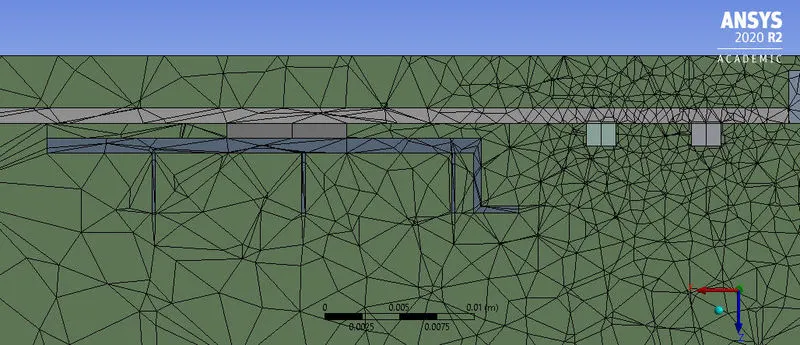
Fig.2- Baseline conformal mesh
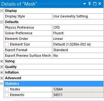
Fig.3- Baseline mesh details
We will refine the above mesh and as there are a lot of quadrilateral geometrical components we can go for uniform meshing arounf the processor as we need to capture the heat gradient.
We have average skewness of 0.275 in the baseline mesh settings and orthogonal quality of 0.726 which is what we expect for a good mesh, low skewness and high orthogonal.
Results:
Simulation .1- Baseline mesh with heat source of 937500000W/m^3 inlet air temperature 300k.
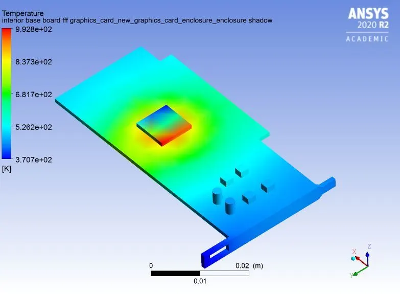
Fig.4- Heat distribution on the board and processor with inlet velocity 5m/s
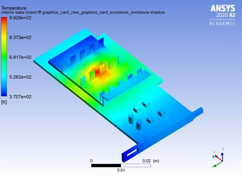
Fig.5- Temperature distribution on the fins with inlet velocity 5m/s
The maximum temeprature attended by the processor is 992.8K. Wall heat transfer coefficient is 506.5749(w/m^2k).
Simulation .2- Inlet velocity changed to 1m/s with same inlet air temperature
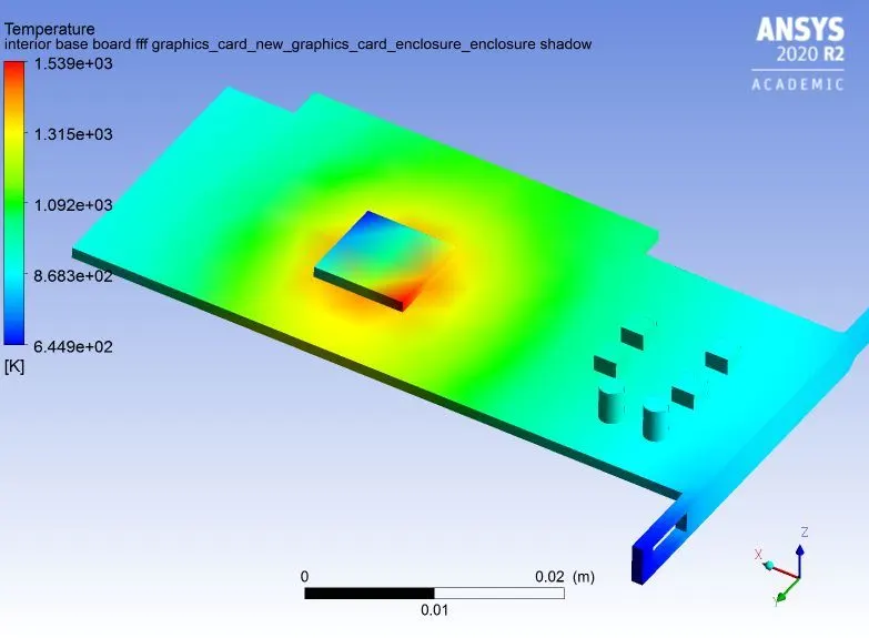
Fig.6- Temp contur with inlet velocity 1m/s on the processor
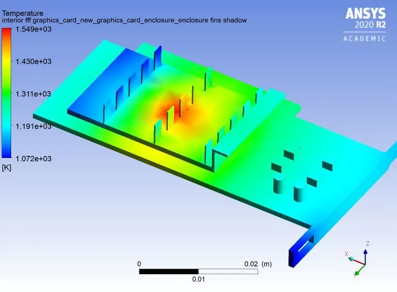
Fig.7- Temperature contour when inlet velocity is 1m/s
On the baseline mesh as the inlet velocity is increased the processor temperature is comparitively low. Heat transfer occurs readily due to convection and conduction to the fins. The fins provide a bigger surface area again to cool down the heat generated.
After simulating with 3 varaiable inlet velocities we refine the mesh. I have used body sizing on the fins, the processor and the base board. The fins have an element size of 1mm. The base board has element size of 2.5mm. The processor has element size of 0.5mm. The overall maximum element size of the geometry is taken to not more than 5mm. I choosed body sizing for refinement because the prime focus of the simulation is on the bodys present. We can have edge sizing also which will refine the mesh even more but it will complicate the meshing also.
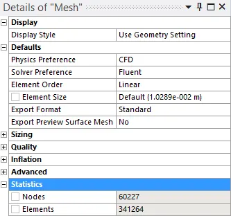
Fig.8- Refined mesh details
Simulation .3- Refined mesh with inlet velocity 5m/s and inlet temperature 300K
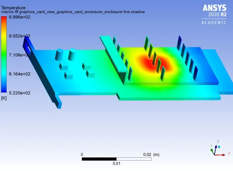
Fig.9- Temperature contour on fins after refining the mesh
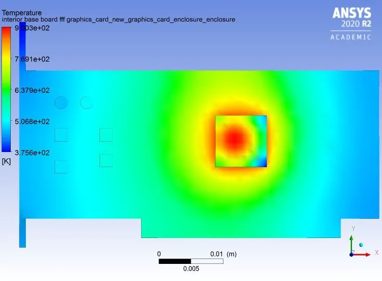
Fig.10- Temperature contour on processor after refining the mesh
The
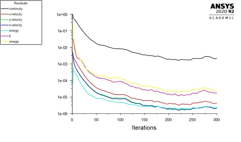
Fig.11- Scaled residuals constantly dropping
The maximum temeprature attended by the processor is 900.3K. Wall heat transfer coefficient is 580.2888(w/m^2k).
Conclusion:
The hotspot on the model is the processor. When inlet velocity is more the heat generated from the processor is comparitively low compared to that of low inlet velocities. The phenomenon is due to convective and conductive properties.