Week 8 - Simulating Cyclone separator with Discrete Phase Modelling
Objective
- Write a few words about any four empirical models used to calculate the cyclone separator efficiency.
- To perform an analysis on a given cyclone separator model by varying the particle diameter from 1 μm to 5 μm and calculate the separation efficiency in each case. Discuss the results. [Use both the velocities as 3m/sec.]
- To perform an analysis on a given cyclone separator model by varying the particle velocity from 1 m/sec to 5 m/sec and calculating the separation efficiency and pressure drop in each case. Discuss the results. [Use particle diameter size as 5 μm for all cases & keep flow velocity same as particle velocity]
Cyclonic separation is a method of removing particulates from an air, gas or liquid stream, without the use of filters, through vortex separation. When removing particulate matter from liquid, a hydro cyclone is used; while from gas, a gas cyclone is used. Rotational effects and gravity are used to separate mixtures of solids and fluids. The method can also be used to separate fine droplets of liquid from a gaseous stream.
A high-speed rotating (air)flow is established within a cylindrical or conical container called a cyclone. Air flows in a helical pattern, beginning at the top (wide end) of the cyclone and ending at the bottom (narrow) end before exiting the cyclone in a straight stream through the centre of the cyclone and out the top. Larger (denser) particles in the rotating stream have too much inertia to follow the tight curve of the stream, and thus strike the outside wall, then fall to the bottom of the cyclone where they can be removed. In a conical system, as the rotating flow moves towards the narrow end of the cyclone, the rotational radius of the stream is reduced, thus separating smaller and smaller particles. The cyclone geometry, together with the volumetric flow rate, defines the cut point of the cyclone. This is the size of the particle that will be removed from the stream with a 50% efficiency. Particles larger than the cut point will be removed with a greater efficiency and smaller particles with a lower efficiency as they separate with more difficulty or can be subject to re-entrainment when the air vortex reverses direction to move in direction of the outlet.
An alternative cyclone design uses a secondary air flow within the cyclone to keep the collected particles from striking the walls and to protect them from abrasion. The primary air flow containing the particulates enters from the bottom of the cyclone and is forced into spiral rotation by stationary spinner vanes. The secondary air flow enters from the top of the cyclone and moves downward toward the bottom, intercepting the particulate from the primary air. The secondary air flow also allows the collector to optionally be mounted horizontally, because it pushes the particulate toward the collection area, and does not rely solely on gravity to perform this function.
Large-scale cyclones are used in sawmills to remove sawdust from extracted air. Cyclones are also used in oil refineries to separate oils and gases, and in the cement industry as components of kiln preheaters. Cyclones are increasingly used in the household, as the core technology in bagless types of portable vacuum cleaners and central vacuum cleaners. Cyclones are also used in industrial and professional kitchen ventilation for separating the grease from the exhaust air in extraction hoods. Smaller cyclones are used to separate airborne particles for analysis. Some are small enough to be worn clipped to clothing and are used to separate respirable particles for later analysis.
Similar separators are used in the oil refining industry (e.g. for Fluid catalytic cracking) to achieve fast separation of the catalyst particles from the reacting gases and vapours. Analogous devices for separating particles or solids from liquids are called hydro cyclones or hydro clones. These may be used to separate solid waste from water in wastewater and sewage treatment.
Discrete Phase Model (DPM)
The discrete Phase Model is a subsection of Multiphase flows. A discrete phase model (DPM) is used when the aim is to investigate the behaviour of the particles from a Lagrangian view and a discrete perspective. The difference between the Lagrangian and the Eulerian view is that fluid behaviour in the Lagrangian view is examined based on particle tracking of a particulate flow, whereas fluid behaviour is considered in the Eulerian view based on the assumption of a finite volume element in the fluid flow path.
In the Discrete Phase Model, the continuous phase is solved using Navier-Stokes equations. At the same time, the discrete phase is simulated by tracking a large number of particles, bubbles, or droplets passing through the calculated continuous flow field. It should be noted that the discrete phase can exchange momentum, mass, and energy with the continuous phase. This method can be made much simpler by ignoring the interaction of particles (as well as droplets and bubbles) with each other. Of course, this can happen when the discrete phase, even with a large mass, has a much smaller volume (less than 10%) than the continuous phase. After each iteration of the continuous phase calculations, the particle paths are calculated and determined separately.
STEPS TO BE FOLLOWED
hear I used 5 different cases to analyse the model
case 1:Entry velocity of 1 m/s and particle diameter of 5 `mu m`
case 2:Entry velocity of 3 m/s and particle diameter of 5 `mu m`
case 3:Entry velocity of 3 m/s and particle diameter of 3 `mu m`
case 4:Entry velocity of 3 m/s and particle diameter of 1 `mu m`
case 5:Entry velocity of 5 m/s and particle diameter of 5 `mu m`
Step 1:
- Initially, start with importing the geometry to the Ansys workbench
- Then the fluid volume is extracted from the model and exported to the mesh
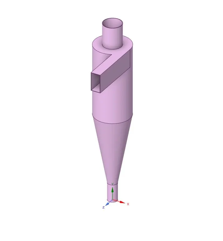
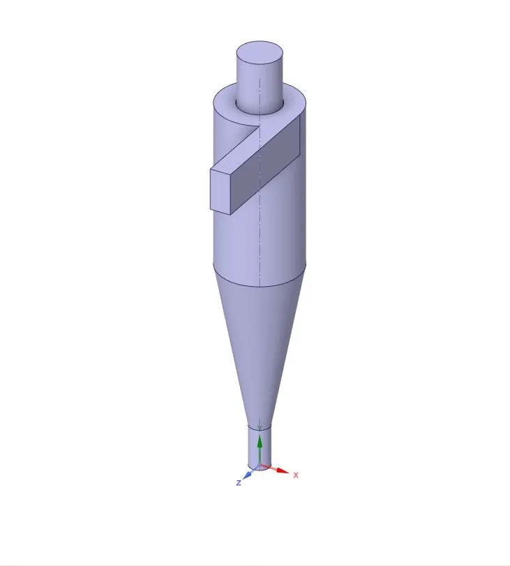
Step 2: From the geometry create a mesh
- Method = Cartesian method
- element size: 5mm
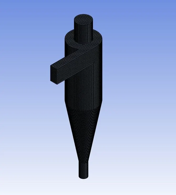
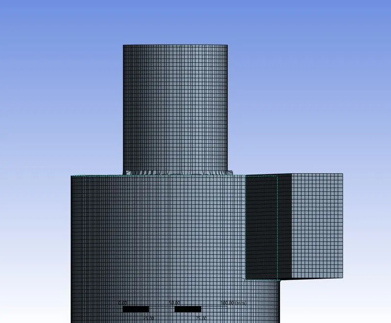
After generating the mesh, the number of nodes and elements is investigated using the statistics option. Then the mesh quality is checked by choosing the mesh matrices option in the quality section.
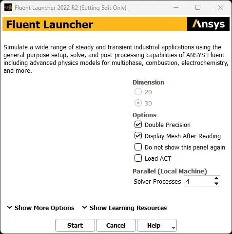
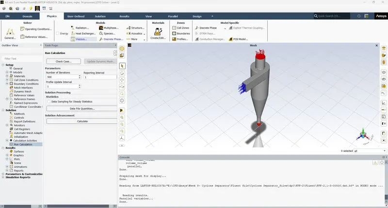
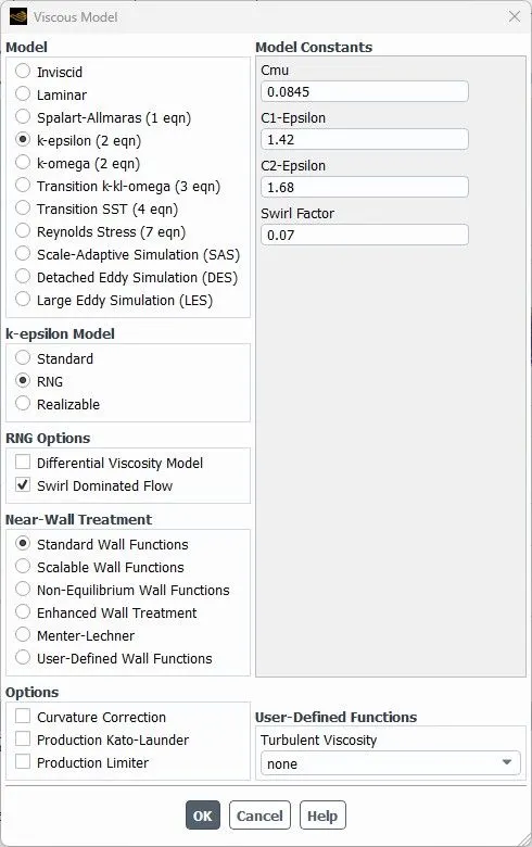
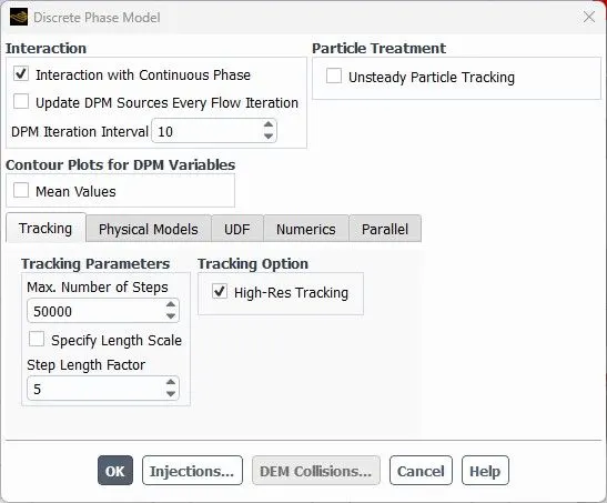
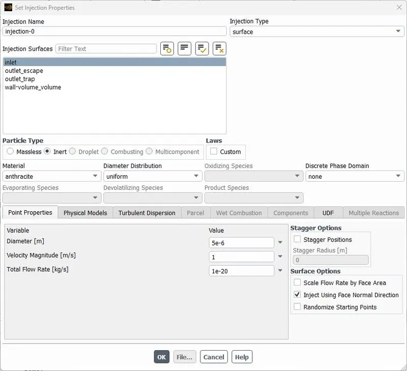
Step 3:In this step, the meshed geometric file has been imported to the fluent module and set the following conditions as follows in the fluent in solving the problem.
This procedure is followed in Ansys fluent
|
SOLVER TYPE |
Pressure based |
|
VELOCITY FORMULATION |
Absolute |
|
TIME |
Steady-state |
|
Gravity |
Applied in the negative y direction |
|
VISCOUS MODEL |
K epsilon swirl dominating the flow |
|
DPM |
Enabled |
|
MATERIAL |
Fluid: air Injection -anthracitete particles |
|
CELL ZONES |
Fluid flow |
|
Inlet |
velocity inlet 1m/s,2m/s and 5m/s |
| Outlet top | particle escape |
| Outlet bottom | Particle escape |
the hybrid scheme is used for the initialization
Results
Case 1
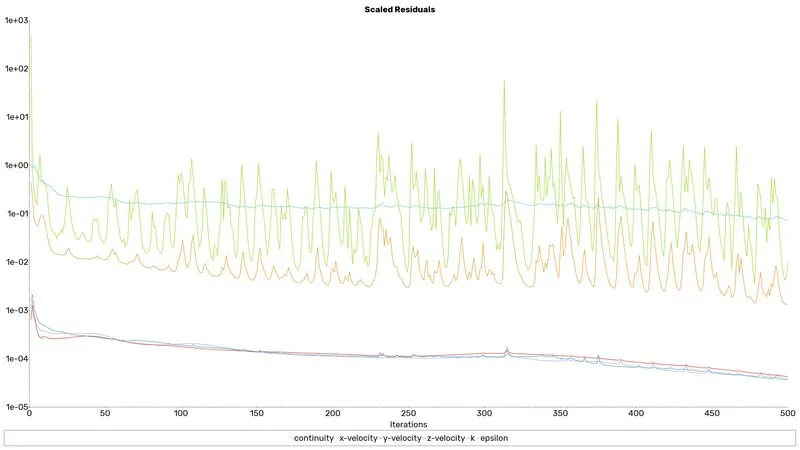
residuals plot
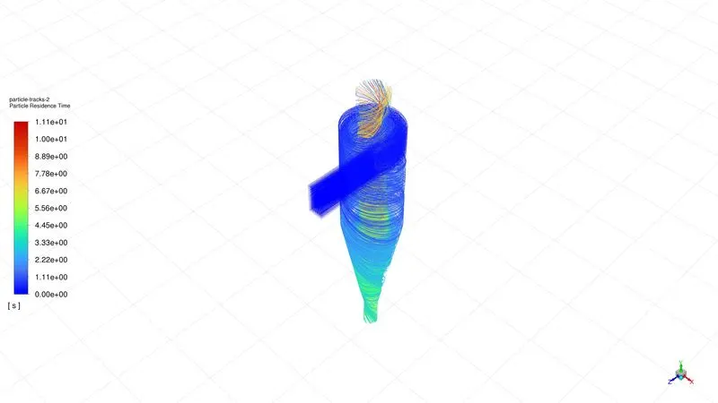
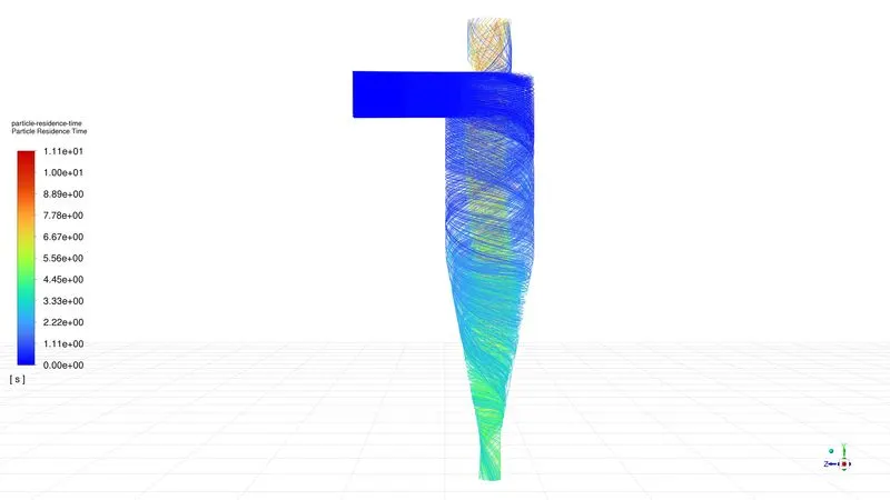
Particle tracking
Particle efficiency

`"separator Efficiency " eta=" particle Traped"/"Particle Tracked" * 100`
`eta=68.51`
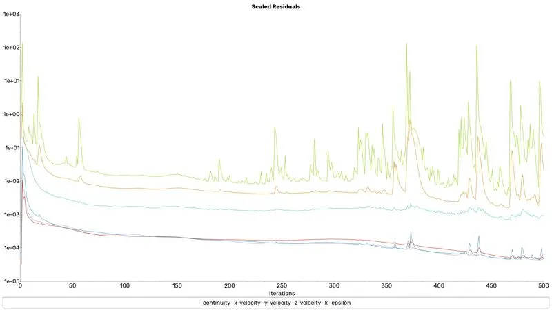
Case 2
residuals plot
Particle tracking
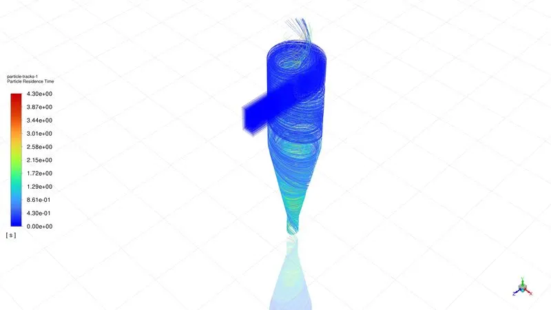
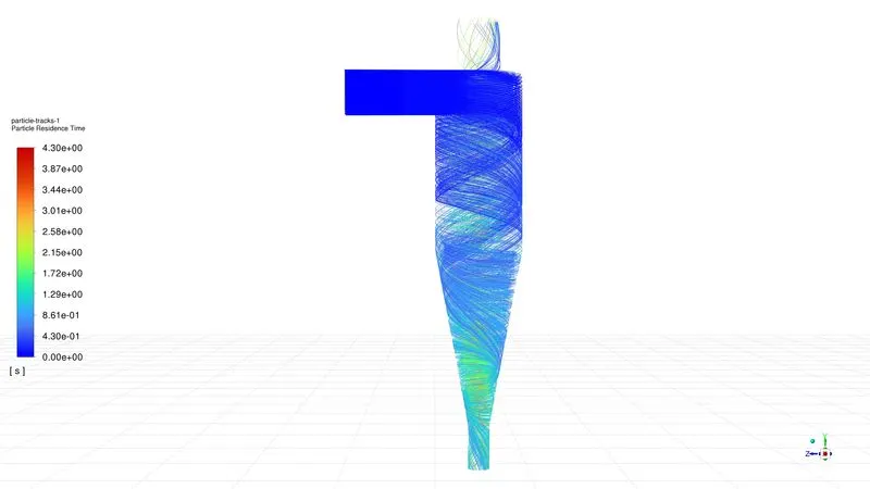
Particle efficiency

`"separator Efficiency " eta=" particle Traped"/"Particle Tracked"*100`
`eta=87.56`
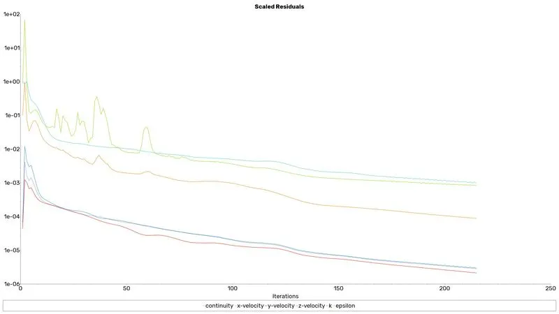
Case 3
residuals plot
Particle tracking
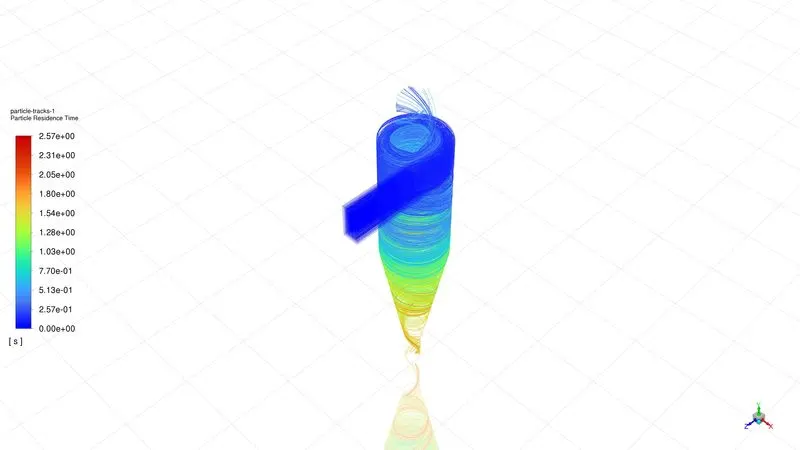
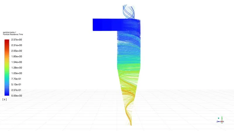
Particle efficiency

`"separator Efficiency " eta=" particle Traped"/"Particle Tracked"*100`
`eta=80.95`
Case 4
residuals plot
Particle tracking
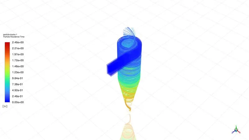
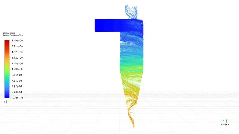
Particle efficiency

`"separator Efficiency " eta=" particle Traped"/"Particle Tracked"*100`
`eta=79.10`
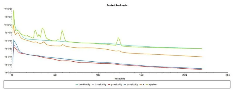
Case 5
residuals plot
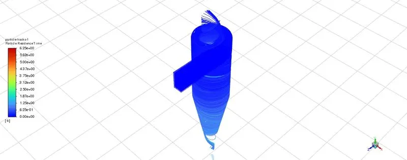
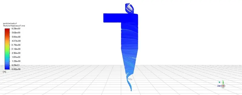
Particle tracking
Particle efficiency

`"separator Efficiency " eta=" particle Traped"/"Particle Tracked"*100`
`eta=74.07`
Solution discussion
The efficiency of the cyclone separator majorly depends on particle size when the size of the particle increases the efficiency of the operator also increases.
When the velocity of the flow increases the particle takes more time to settle down or takes more time to complete.
At high velocity, the particle starts circulating inside the separator and takes more time to settle down or we need to wait till the circulation of the particle is disturbed by another particle by creating an impact on its
| case | Number of particles tracked | Number of particles trapped | Number of particles escaped | Incomplete particle | efficiency |
| 1 (1m/s,5μm) | 378 | 259 | 119 | 0 | 68.51 |
| 2(3m/s,5μm) | 378 | 331 | 47 | 0 | 87.56 |
| 3(3m/s,3μm) | 378 | 306 | 72 | 0 | 80.95 |
| 4(3m/s,1μm) | 378 | 299 | 79 | 0 | 79.10 |
| 5(5m/s,5μm) | 378 | 280 | 70 | 28 | 74.07 |