Week 8 - Simulating Cyclone separator with Discrete Phase Modelling
AIM:To perform analysis on cyclone separator, calculate the separation efficiency and pressure drop and do for varying the particle diameter from 1 μm to 5 μm.
INTRODUCTION:
A cyclone separator is an economical device for removing the particulate solids from a fluid system. The induced centrifugal force is tangentially imparted on the wall of the cyclone cylinder. This force, with the density difference between the fluids and solid, increases the relative settling velocity.
THEORY:
Cyclone separators are generally able to remove somewhere between 50-99% of all particulate matter in flue gas. How well the cyclone separators are actually able to remove this matter depends largely on particle size. If there is a large amount of lighter particulate matter, less of these par0ticles are able to be separated out. Because of this, cyclone separators work best on flue gases that contain large amounts of big particulate matter.
1.Lapple model:
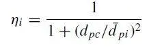
Lapple model was developed based on force balance without considering the flow resistance. Lapple assumed that a particle entering the cyclone is evenly distributed across the inlet opening. The particle that travels from inlet half width to the wall in the cyclone is collected with 50% efficiency. The semi empirical relationship developed by Lapple to calculate a 50% cut diameter.The efficiency of collection of any size of particle is given by :
2.Koch and litch model:
kotch and litch collection theory recognized the inherently turbulent nature of cyclones and the distribution of gas residence times within the cyclone. kotch and litch described the particle motion in the entry and collection regions with additional following assumptions:The tangential velocity of a particle is equal to the tan- gential velocity of the gas flow, i.e. there is no slip in the tangential direction between the particle and the gas.The tangential velocity is related to the radius of cyclone by: uR^n= constant.Grade efficiency

3.Li and Wang Model:
The Li and Wang model include particle bounce or re-entrainment and turbulent diffusion at the cyclone wall. A two-dimensional analytical expression of particle distribution in the cyclone is obtained.
The resultant expression of the collection efficiency for particle of any size is given as
E = 1 − exp{−lambda*theta(1)}
where
theta1 = (2*pie(S + L))/a
4. Iozia and Leith model
This model assumes that the particle carried by the vortex is controlled by centrifugal force and flow resistance. The collection efficiency is calculated from the below formula,
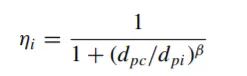
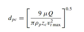
dpc is the 50% cut size given by barth model
SLOVING AND MODELLING APPROACH:
1. First i open the workbench and then i drag the anasys fluent into the work space. then i open then geometry on the popup and i open the spaceclaim and import the geometry into the spaceclaim.
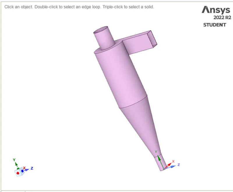
fig: Raw geometry.
2.then i used the option to extract volume to extract the inside volume of the cyclone separator.
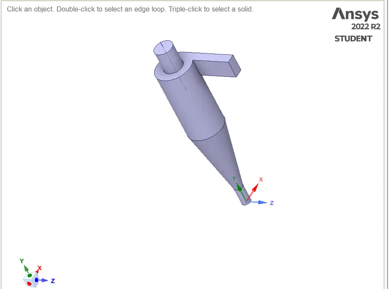
fig: volume extracted of the cyclone separator.
3.then i used the option suppress for physics not to use the wall geometry of the cyclone separator. then i open the meshing part.
4. here i generated the defult mesh then i used the option method in that i used the cartesian meshing that is the Structural meshing.
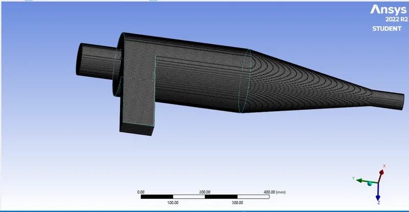
fig: meshed cyclone separator.
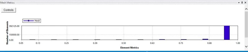
fig: mesh quality.
5. then i have given the name selection of the geometry like inlet,outlet trap and outlet-escape.
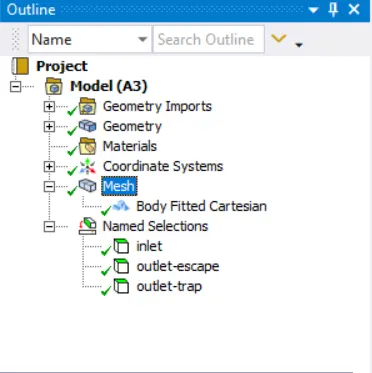
fig: meshing setup.
6. then i open the solver setup to solve the problem here i have given the gravity in y axis is -9.81 and i given the viscous model is k-epsilon RNG and swirl dominated flow.
7. then i given the discrete phase model in the i have selected the interaction with continuous phase then selected the injection to creat for the inlet of surface and i given the velocity in Z axis and diameter of the anthracite particle size and type of flow.
8.then i have given the boundary conditions like
Inlet and wall:- Reflect and set the inlet velocity
Outlet(Top):- Escape
Outlet(Bottom/dustbin) - Trap.
9.then solver method is standrad and the i initialization the sover the i run it for 300 iterations for all the cases.
CASE 1- particle size 5 μm and velocity of inlet 3m/sec.
CASE 2- particle size 1 μm and velocity of inlet 3m/sec.
CASE 3- particle size 3 μm and velocity of inlet 3m/sec.
CASE 4- particle size 5 μm and velocity of inlet 1m/sec.
CASE 5- particle size 5 μm and velocity of inlet 5m/sec.
OUTPUT:
CASE 1
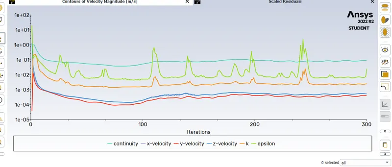
fig: Residual plot.
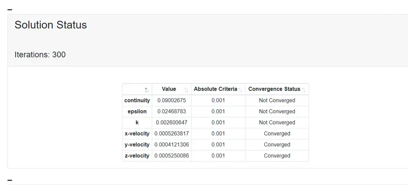
fig: converged and not converged
CASE 2
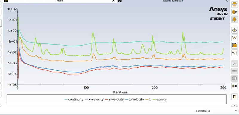
fig: Residual plot.
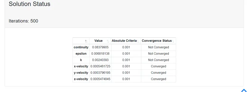
fig: coverged and not converged.
CASE 3
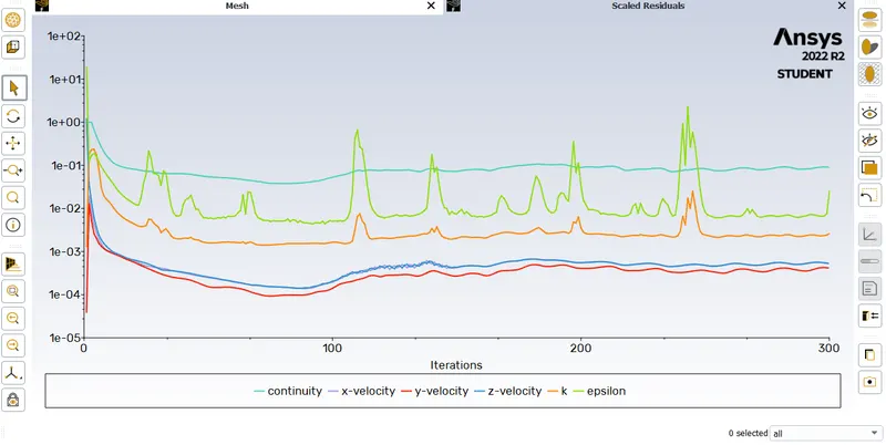
fig: Residual plot
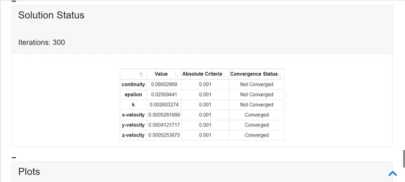
fig: converged and not converged.
CASE 4

fig: Resdual plot.
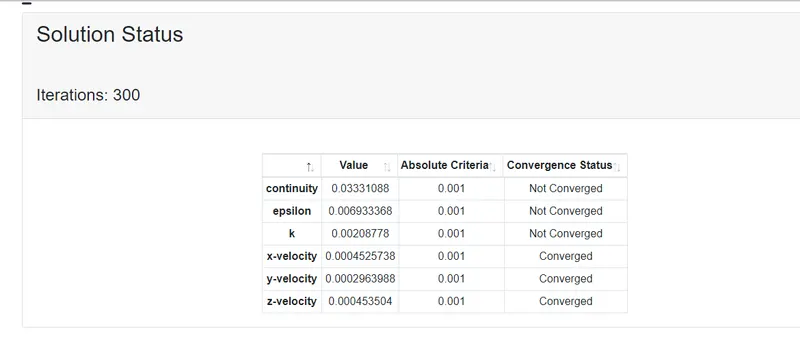
fig: converged and not converged
CASE 5
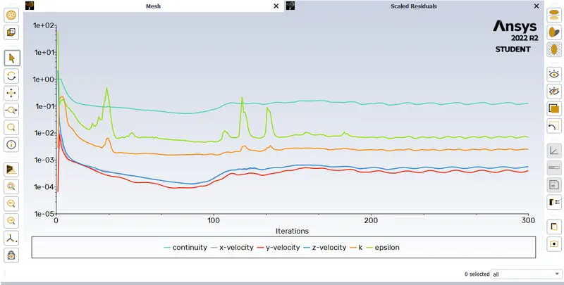
fig: Residual plot
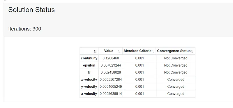
fig: converged and not converged.
RESULT:
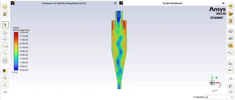
fig: velocity contour
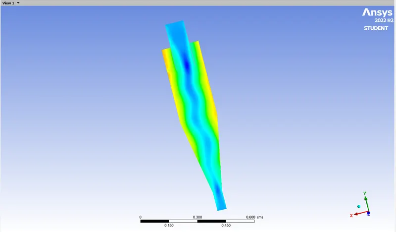
fig: pressure contour.
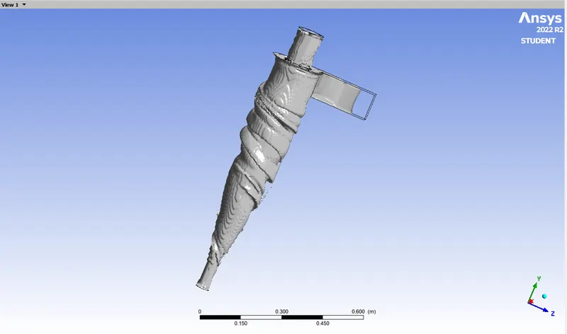
fig: vertex core region
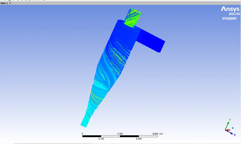
fig: anthracit particle time
case 2
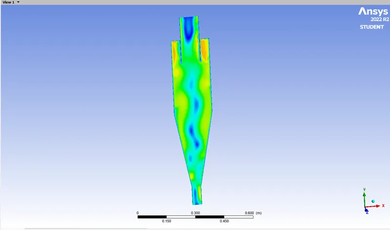
fig: pressure contour
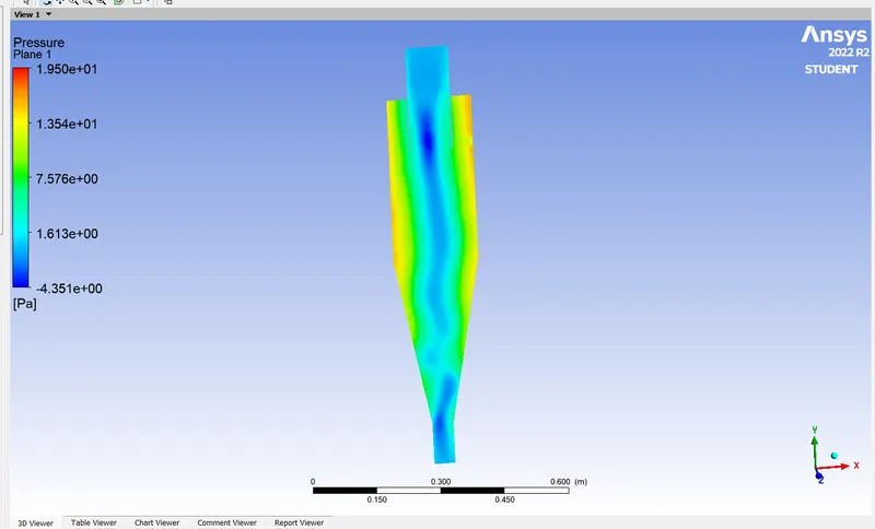
fig: pressure contour
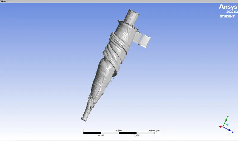
fig: vertex core region
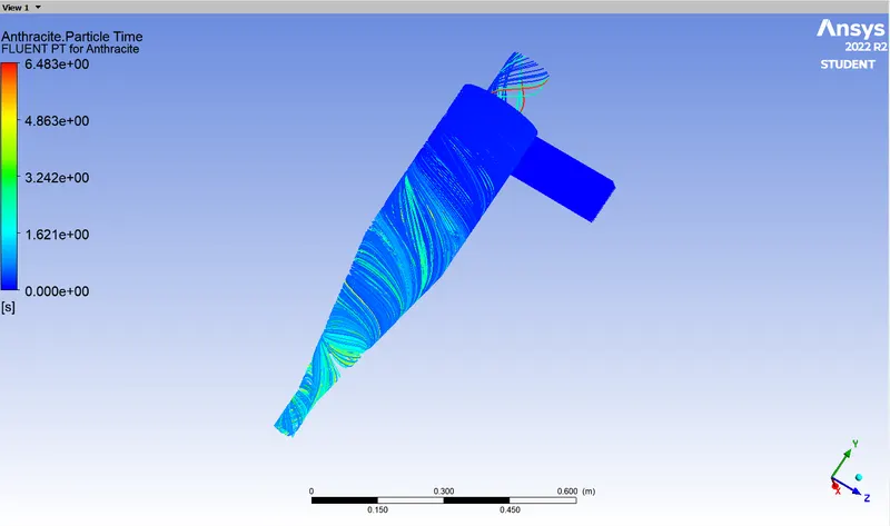
fig: anthracite particle time.
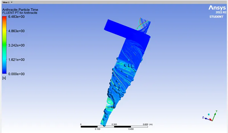
fig: anthracite particle time
CASE 3
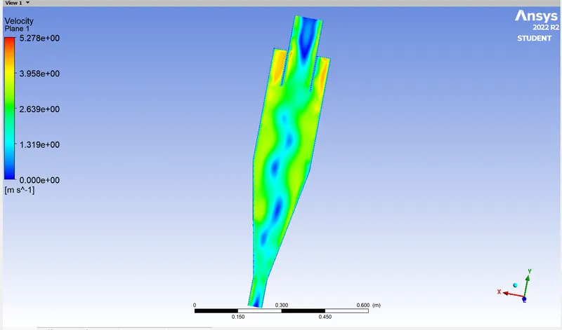
fig: velocity contour
fig: pressure contour
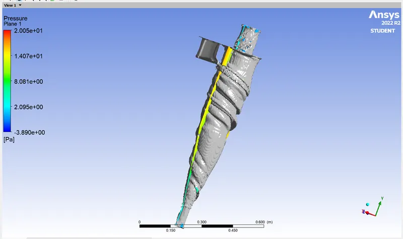
fig: vertex core region.
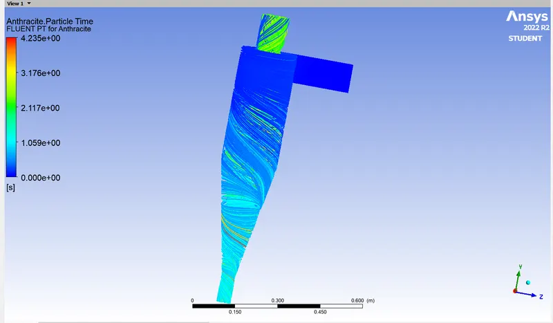
fig: anthracite particle time.
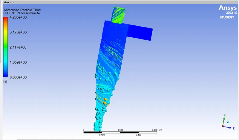
fig: anthracite particle time
CASE 4
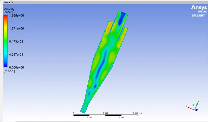
fig: velocity contour
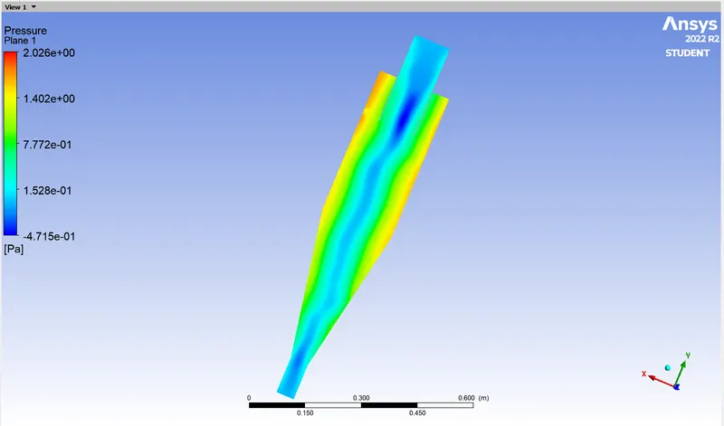
fig: pressure contour
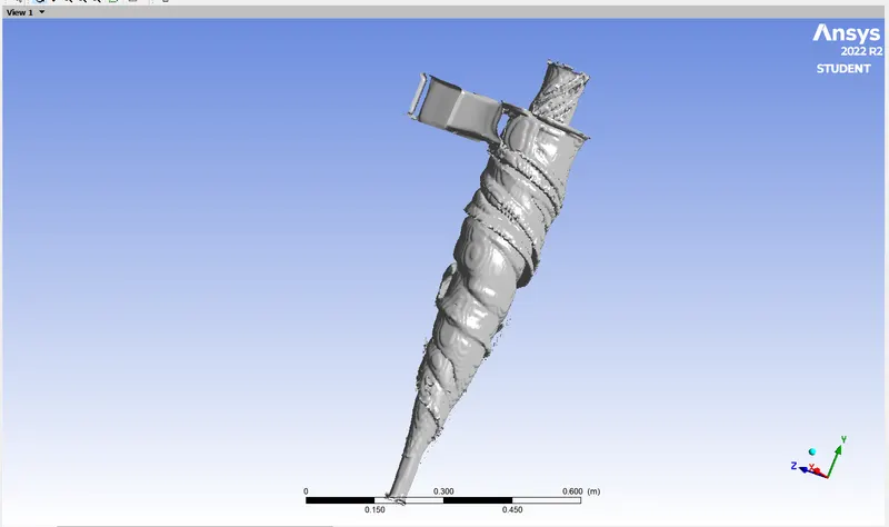
fig: vertex core region
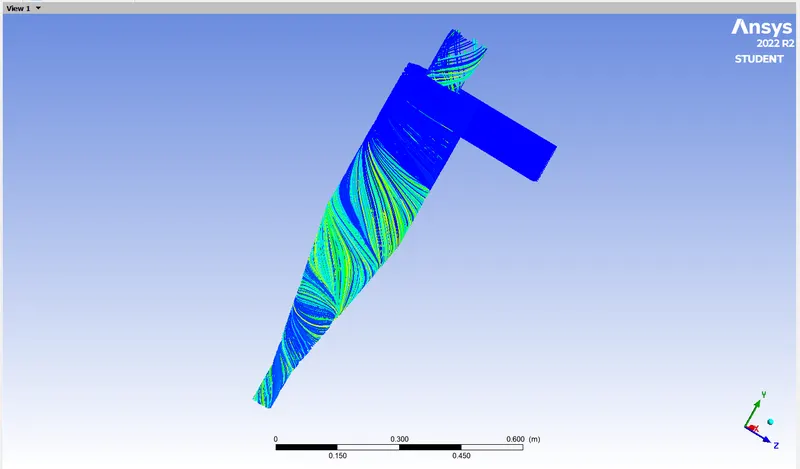
fig: anthracite particle region.
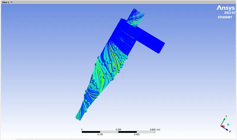
fig: anthracite particle time
CASE 5
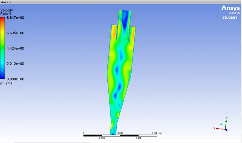
fig: velocity contour
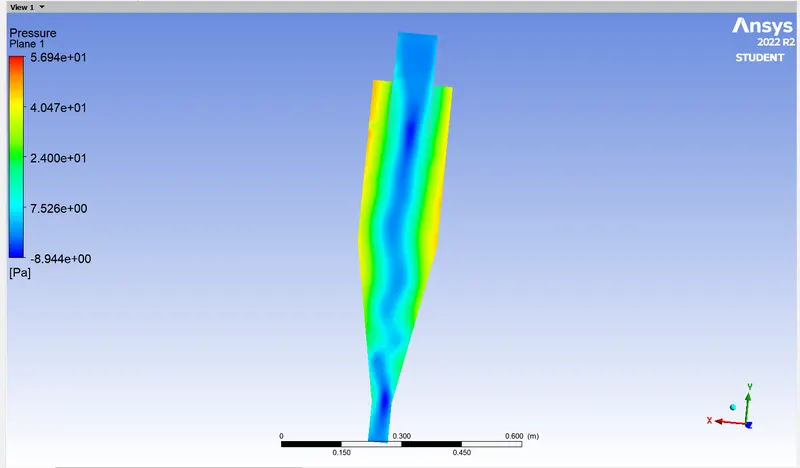
fig: pressure contour
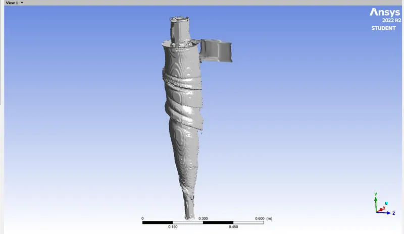
fig: vertex core region
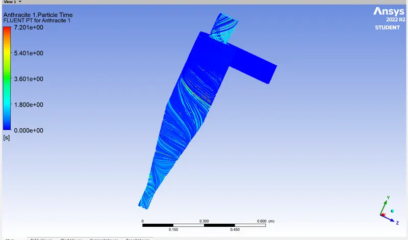
fig: anthracite particle time
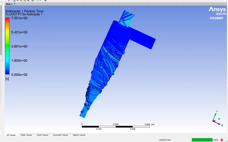
fig: anthracite particle time.
TABLE FOR ALL CASES:
| velocity (m/sec) | anthracite particle diameter (μm) | pressure drop (pa.) | efficiency % | |
| case 1 | 3m/sec | 5μm | 21.288 | 65.07% |
| case 2 | 3m/sec | 1μm | 20.563 | 84.92% |
| case 3 | 3m/sec | 3μm | 21.349 | 88.89% |
| case 4 | 1m/sec | 5μm | 2.244 | 60.31% |
| case 5 | 5m/sec | 5μm | 58.972 | 73.80% |
CONCLUSION:
here i conclude that the efficiency is mainly depends on the velocity and the anthracite particle diameter. if the velocity is low and the particle size is large then the efficiency is low, if the velocity is high and the particle size is small then the efficiency is more. the velocity is lows the pressure is high at the wallof the cyclone separator. the pressure drop is more because the velocity is increasing gradually.