Week 8 - Simulating Cyclone separator with Discrete Phase Modelling
- INTRODUCTION:jhfyf
- Aim:- To perform analysis on cyclone separator and calculate the separation efficiency and pressure drop.
- Objective:-
- To write a few words about any four empirical models used to calculate the cyclone separator efficiency.
- To perform an analysis on a given cyclone separator model by varying the particle diameter from 1 μm to 5 μm and calculate the separation efficiency in each case. Discuss the results. [Use both the velocity's as 3m/sec.]
- To perform an analysis on a given cyclone separator model by varying the particle velocity from 1 m/sec to 5 m/sec and calculate the separation efficiency and pressure drop in each case. Discuss the results. [Use particle diameter size as 5 μm for all cases & keep flow velocity same as particle velocity]
- Four Empirical Models used to calculate the efficiency & pressure drop are as follows:
- Iozia and Leith Model :
Iozia and Leith:logistic model is a modified version of Barth Model, which is developed based on force balance. The model assumes that a particle carried by the vortex endures 165 the influence of two forces: a centrifugal force, Z and a flow resistance, W. The collection efficiency ηi of particle diameter dpi can be calculaed from
ηi =1 /(1 + (dpc/dpi))^β
β is an expression for slope parameter derived based on the statistical analysis of experimental data of a cyclone with D = 5`μm`. - Li and Wang Model :
The Li and Wang model includes particle bounce or reentrainment and turbulent diffusion at the cyclone wall.The concentration distribution in a cyclone is given as: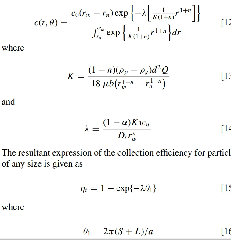
- Koch and Licht Model:Koch and Licht [2] collection theory recognized the inherently turbulent nature of cyclones and the distribution of gas
residence times within the cyclone. Koch and Licht describedparticle motion in the entry and collection regions with the additional following assumptions:
• The tangential velocity of a particle is equal to the tangential velocity of the gas flow, i.e. there is no slip in the
tangential direction between the particle and the gas.
• The tangential velocity is related to the radius of cyclone by:5 um.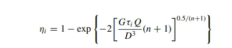
- Lapple Model
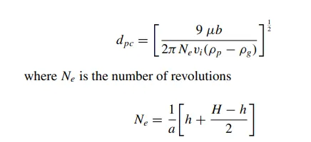
Lapple model was developed based on force balance without considering the flow resistance. Lapple assumed that a par215 ticle entering the cyclone is evenly distributed across the inletopening. The particle that travels from inlet half width to the wall in the cyclone is collected with 50% efficiency. The semi empirical relationship developed by Lapple to calculate a 50% cut diameter.
- PROCEDURE (Solving & Modelling approach)
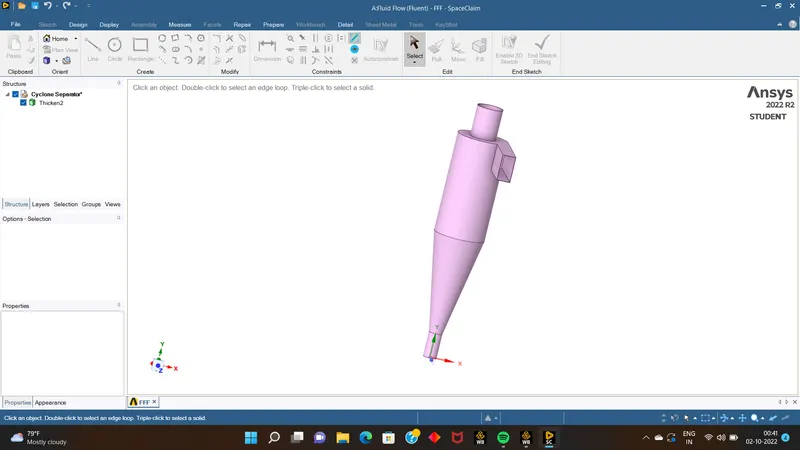
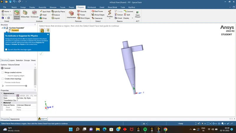
- firstly download the model from the source & from ANSAS FLUENT go to space claim & do the volume exclude from the tool & exit from space cliam.
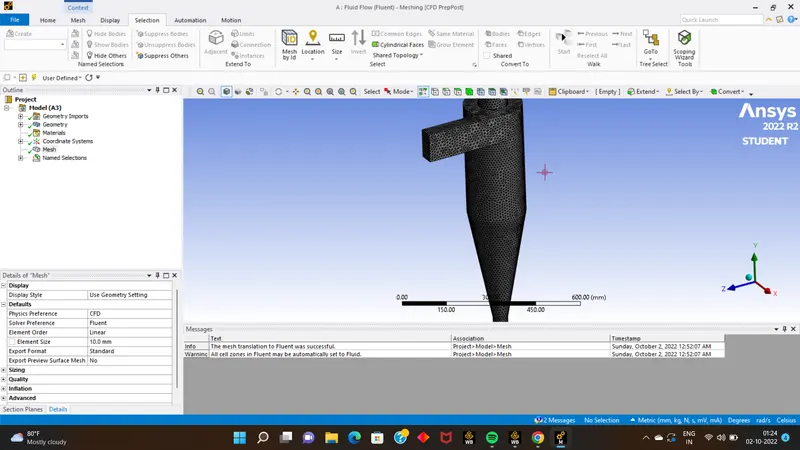
- now open the meshing part , mesh the model with targetlength 10 , & name the required respective surfaces as inlet,outlet1,outlet2.
- than close the meshing part & open the setup part.
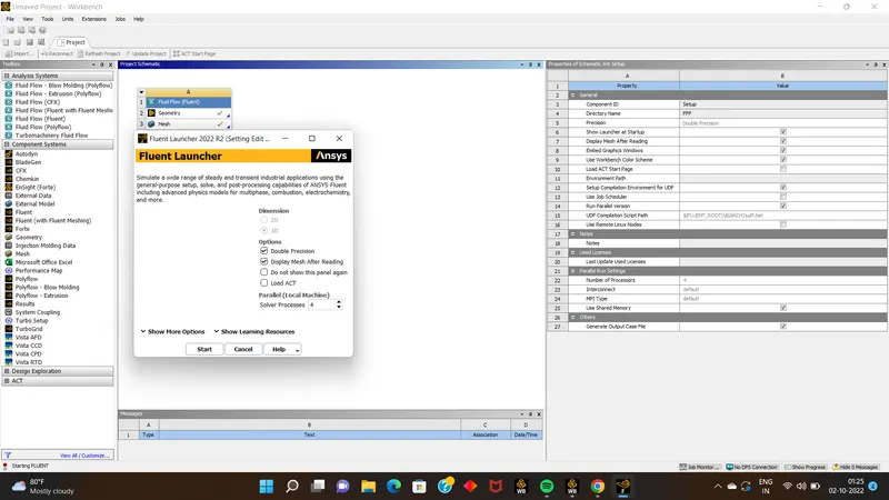
- than assign the required solver to solve the simulation, as shown below.
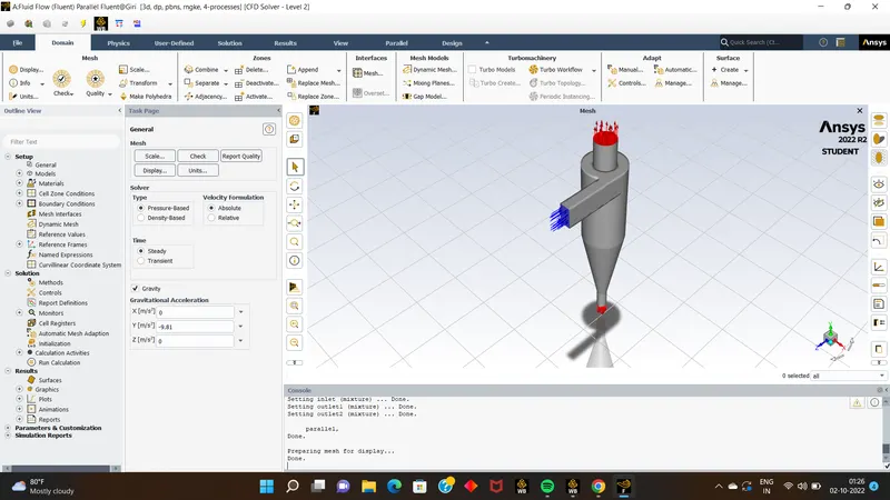
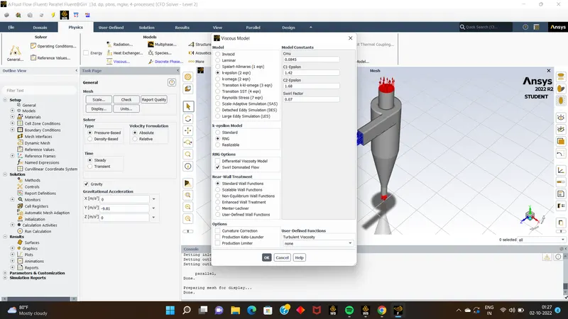
- Next open the Descret phase model,than unable the the required option as shown in below SS.
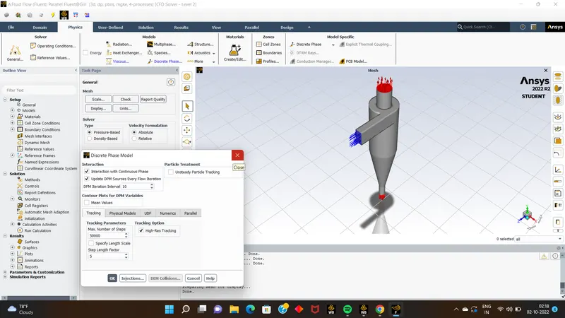
- than create the injection in DPM setup dilouge box only, give the required velocity & diameter for the inlet particle.
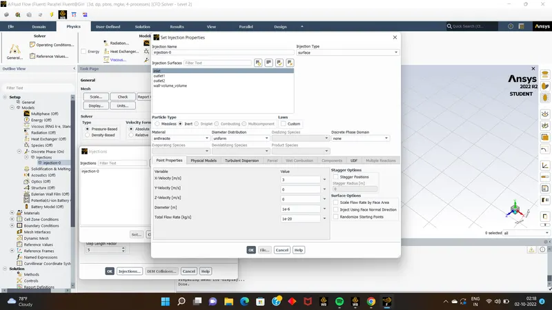
- for the first case lets give the diameter as 1e-6. & velocity as 3m/s.
- Than go to solution part > models & assign the turbulet kinetic energy & discipation rate as second order upwind.
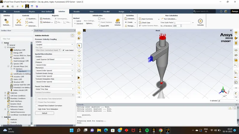
- than go for standard initalization > more options> compute from inlet.
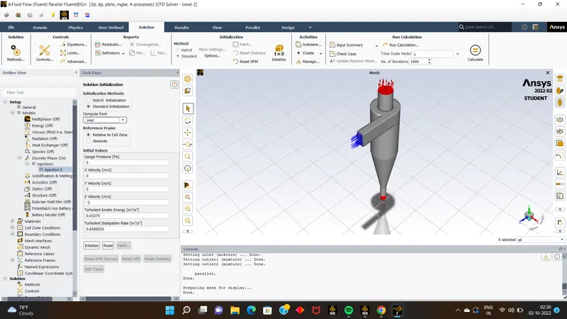
- than run the calculation for 1000 itrations. & than export the particle data history > browse it & save it & even we can write it .
- than Go for results part
- unable wall volume coloumn & go for render & enable the transperancy.
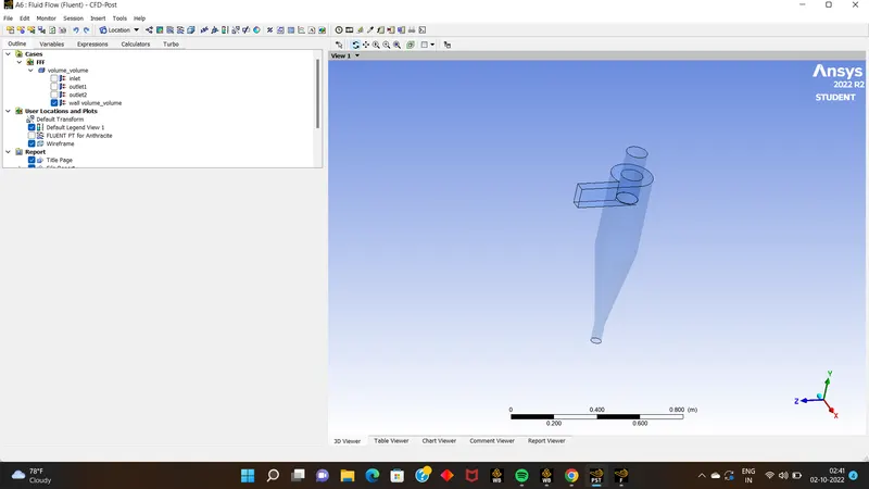
- than import the data which you have saved it before & double click on it ,and change the value of max track to 25 to 100,& change to colour to constant to variable of Antheracite particle time & click on apply to see the changes.
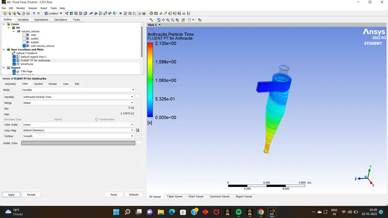
- than we can also look for the annimation movie how the particle travels through the path .
- Results: In this simulation we can observe that almost 200+ particles entered from inlet ,& all of them havee traped at outlet2 , none of them have escaped from the outlet1. so i think there is 100 % seperation effency in this case.
CASE 2:(particle diameter 3e-6)
again we need to repeat the same procedure,& during creating injection in DPM just we need to change the diameter to 3e-6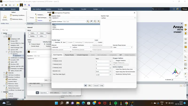
the results obtained were same as previous simulation no particles were escaped ,all were traped.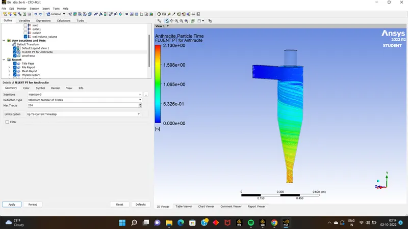
Case 3: (Now we will look for diameter 5e-6)
Repeat the same procedure as we done foor 1st &2nd,& observe the results.
in 3rd case we can see the difference that 3 particles have been escaped 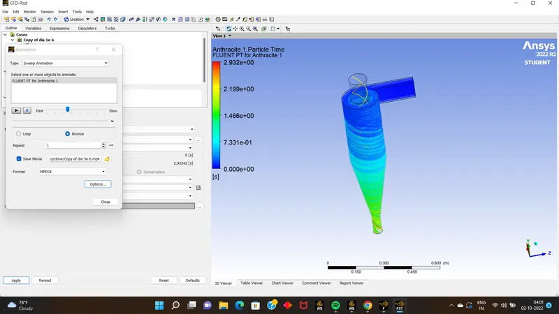
here the seperation efficiency was upto around 98.2 %, the formula used wwas s.e= 100*(1-Cv/Cp)
- CONCLUSION : here we can conclude such that as the particle diameter increases the seperation of particle from cyclone seperator., we can see when the dia was 1,3Um there was no seperation of particle,but when we increased the dia of particle to 5 we can see 98.2 seperation efficiency.
3 now we do simulation for constant diameter 5e-6 by varying particle velocity from 1to 5 m/s:
- case 1 : by simulating inlet particle velocity as 1m/s
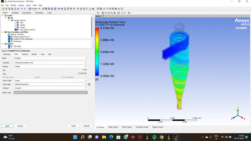
- here also the seperation efficiency is 100 becz no particle has escaped.
CASE 2: inlet particle velocity as 3 m/s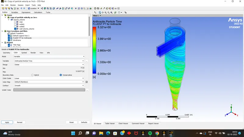
- there was change observed
CASE 3 : Inlet Velocity as 5 m/s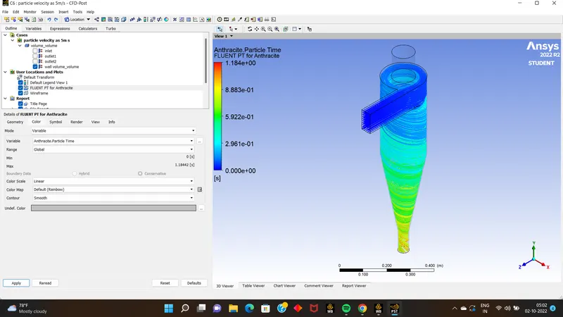
- here also the results were obtained was same as case 1,2
CONCLUSION:
from this simulation we can conclude that inlet particle velocity does not matter ,but particle diameter matters .