Week 2 Challenge : Surface meshing on a Pressure valve
- Aim : To check for the geometrical errors &perform Topology clean up accordingly & deploy meshing to the model with 3 different cases by changing target length.
- Objectives: To flow the step by step tools to achive the the aim 1 Topology Clean up, 2 assigning pid's to each part, 3 finally meshing to the model.
- Procedure :
- Get the model from the File>open>downloads>challange-2 pressure valve.
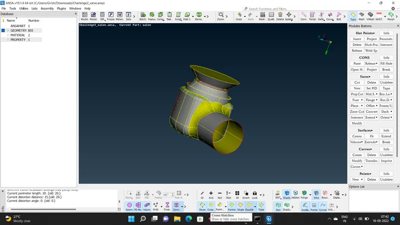
- After getting the model on screen turn on the cross hatches tool.
- Next we have to check the geometric errors,so go to check tool >check for geometry>A check manager dialouge occurs >select the required options to be checked & click on execute & some errors will be displayed & our task is to clear all the errors
- Errors will be single cons & crack errors that need to be cleared.
- Now to check the single cons errors click on the tools ,to remove cross hatches ,double cons marks &click on shadow mode of a model ,so now we can clearly see the number of single cons to be cleared .
- Now using the tool from Faces section> we need to clear the erroers & make the closed model by using tools like New , Fill Holes.
- when we click on tool New > a dialouge box appears with 4 options of surface type to add a new faces to the model namiely,1 exesting surface ,2 planner ,3 Fitted , 4 coons .
- After selecting any one of the options among 4,click the scrool button to preview the new surface at required face of the model & finally click ok to add face .
- Simillarly fill all the single cons & cracks, to clear all the errors.
- Next make the model closed by adding a new surface,where required by using same tool from new .
- And when you close the bottom surface of the model, a tripple con occurs which is not considerd as an error.
- Again follow the same step 3 to check the errors in the model if no errors found expect triple cons procced the further steps ,else repeat the clean up part for the model till no errors occurs.
- Next step is using tool Cut from the Faces section, cut the unrequired cons which will be disturbing the meshing part of the model,the cut cons will displayes the orange lines.
- Next step is from Tool Drawing style ,select PID from tool Draw Mode & Model colour changes to light brown.
- Than go to properties & a dialouge box appears & create a new PSHELL from the options & rename them parts name respectively.
- After creating New Shells,Assign them to there particular part by there names with each different colours to avoid confusions.
- Now to apply /assigning the shell to body ,you need to just select only outer surface,so Use the tool PID region ,so PID will be applied to only outer surface of the model.
- For assigning PIDs to the inner part exludes all the outer parts using Not tool & use the Lock tool So just inside parts will be visible and you can easilly assign the remaining PIDs for the inner parts of the model.
- Now unlock the lock tool & click on All tool to Retrive back whole model which will be assigned by PIDs .
- Now jump into the meshing part
- Now using the tool Length assign the required length to perimeter & macros .
- Still 2 more parameters to be assigned those are Mesh parameters, Quality cretria, In mesh parameters assign the desired target length & change the element type to tria,& In quality cretria assign the required options like maximum target length, minimum target length etc.
- Next come to Mesh Generation tool & select the spot mesh tool.
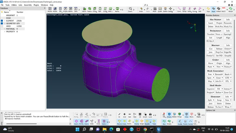
- Than select the faces of the model & click scroll button to deploy the mesh on selected surfaces ,& for inner parts Repeat the same procedure as we did for assigning the PIDs for inner surface of the model & deploy the meshing to inner surface of the model.
- reapeat the sames steps from 20 to achive the meshing of differnet target length to the model.
- Learning Outcomes :
- Learne to clean the Topology cleanup of the given model using best suitable tools.
- Assigning the PID's to the particular parts with respect to there names & different colour.
- To deploy the meshing for the whole model containg more than 1 part.
- Results :
- When target length =1mm, number of trias =209912
- When target length =3mm, number of tias =23926
- When target length =5mm, number of tias =8812
- Conclusions :
- As we done meshing for 3 target lengths the conclusions can be drawn from the above results is as follow , As target length goes on increases the number of trias will be decreased.
- As traget length increases the fine finish of the model cant be obtained as we can see in particular images.
- so to obtain the fine finishing of mesh small target length should be choosed.