Week 8 - Simulating Cyclone separator with Discrete Phase Modelling
OBJECTIVE:
We will be performing an analysis on a cyclone separator and calculating its separating efficiency and pressure drop. This analysis is focused on two parameters: Particle Diameter and Particle Velocity.
Two types of cases will be simulated:
- Varying particle size from 1 micron to 5 microns at constant velocity of 3 m/s
- Variable particle velocity from 1 m/s to 5 m/s at a constant particle diameter of 5 micron
We will compare the separating efficiency and pressure drop for all the cases.
INTRODUCTION AND THEORY:
Cyclone Separator: Cyclone separators, often known as cyclones, are dry scrubbers that employ the law of inertia to separate particles from exhaust gases. Cyclone separators are one of many tools used to reduce air pollution that is referred to as "pre-cleaners" since they often remove bigger particles. This avoids the need for later, more refined filtration techniques to handle larger, more abrasive particles.
Many empirical models have been designed to calculate Cyclone Efficiency:
- Iozia and Leith Model: The logistic model created by Iozia and Leith (1990) is a modified version of the Barth (1956) model and is based on force balance. According to the model, a particle being carried by a vortex is subject to a centrifugal force and a flow resistance.
- Li and Wang Model: The Li and Wang (1989) model incorporates turbulent diffusion near the cyclone wall and particle bounce or re-entrainment. It makes it possible to express the particle distribution in the cyclone analytically in two dimensions.
- Koch and Licht Model: Developed by Koch and Licht in 1977, identified both the distribution of gas residence periods within cyclones and the intrinsically turbulent nature of cyclones. Koch and Licht describe particle mobility in the entrance and collecting zones.
- Lapple Model: The force balance-based Lapple (1951) model was created without considering the flow resistance. Lapple made the supposition that a particle entering the cyclone is dispersed uniformly over the inlet hole. The particle is gathered in the cyclone with a 50% efficiency from the entrance half width to the wall.
GEOMETRY:
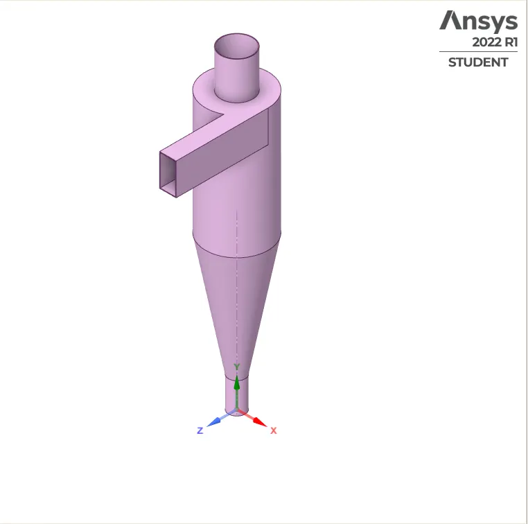
We have a 3D model of the Cyclone Separator:
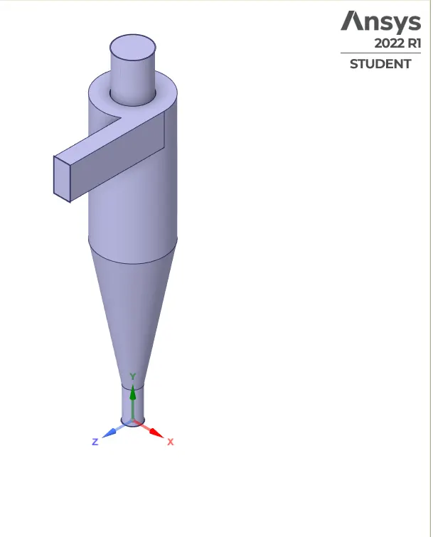
We will extract the volume from this model which will serve as our model for this simulation:
MESHING:
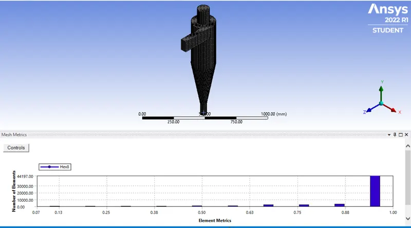
We will use cartesian mesh for this model, with an element size of 10 mm.
SETUP:
We use a pressure-based steady-state solver, with gravity enabled across the negative y-axis.
For Viscosity Model:
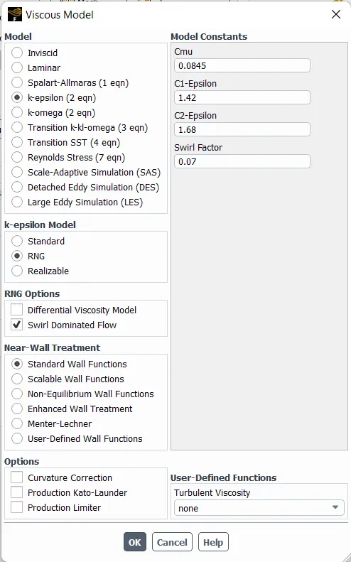
we are using the K-epsilon RNG model, which is great for swirling flow.
We also need to model the particles using the Discrete Phase Model(DPM):
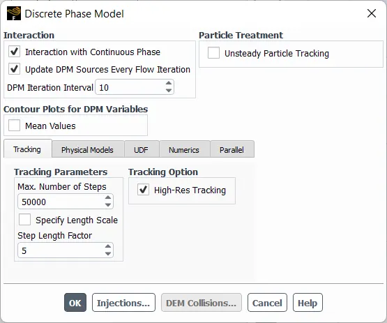
We will be using anthracite as the injection material, with varying velocity and particle size:
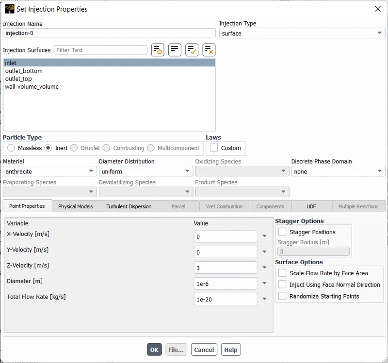
For boundary conditions, we will be varying velocity for the 2nd case and set it to 3m/s for the 1st case. As for DPM boundary conditions:
-
Inlet and wall:- Reflect
-
Outlet(Top):- Escape
-
Outlet(Bottom) - Trap
RESULTS:
CASE I: Varying Particle Diameter, V = 3 m/s:
1 micron:
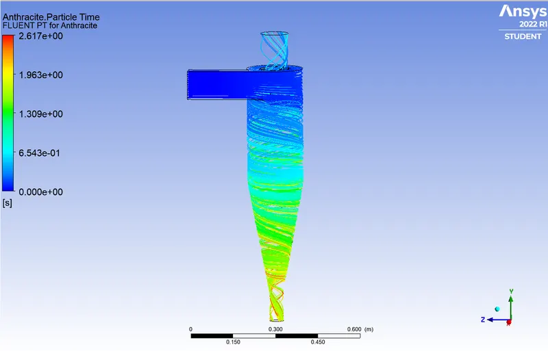

Separation Efficiency = (No. of Particles Trapped/ No. of Particles Tracked) * 100
= 66/91 * 100 `implies` 72.52 %.
2 micron:
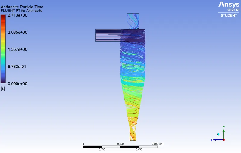

Separation Efficiency = 66/91 * 100 `implies` 72.52 %.
3 micron:
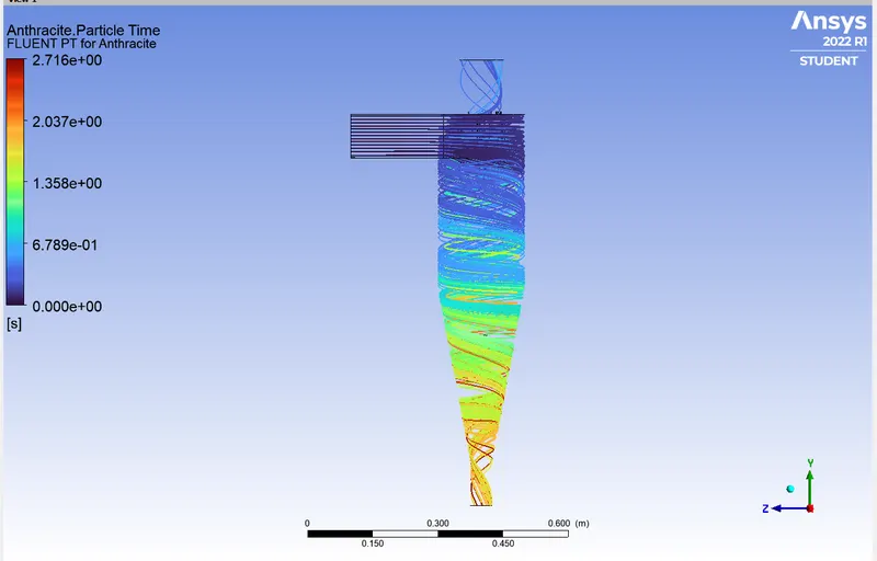

Separation Efficiency = 69/91 * 100 `implies` 75.82 %.
4 Micron:
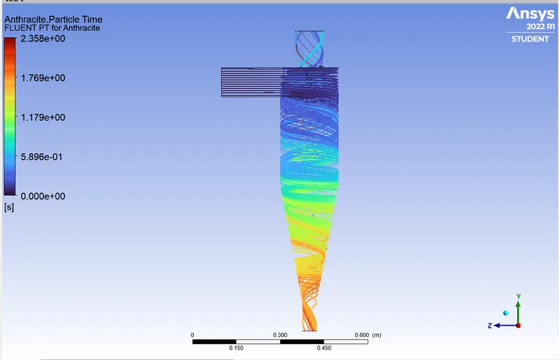

Separation Efficiency = 61/91 * 100 `implies` 67.03 %.
5 micron:
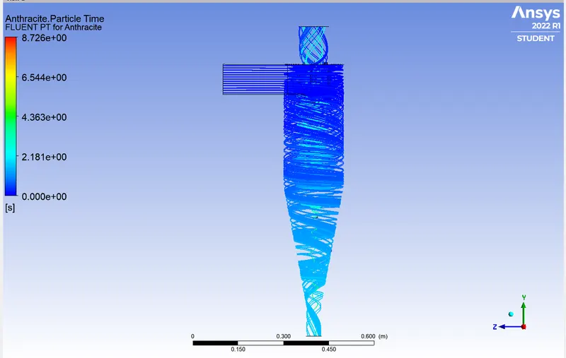

Separation Efficiency = 50/91 * 100 `implies` 54.94 %.
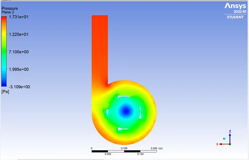
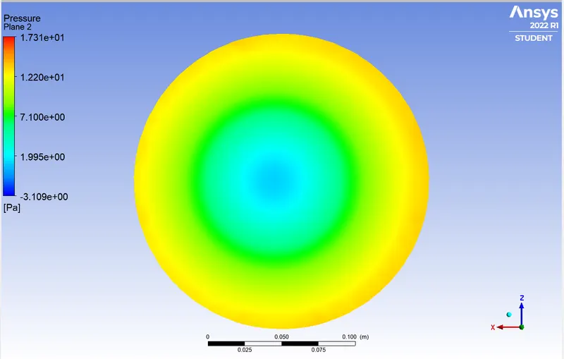
All the cases for varying diameter had a similar pressure profile:
Pressure Profile:
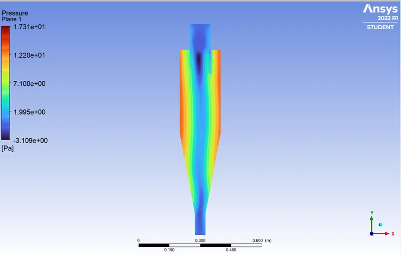
Total Pressure: 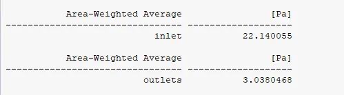
Pressure Drop = 22.14 - 3.03 `implies` 19.11 Pascal
CASE II - Varying Velocity, Particle Diameter = 5 micron:
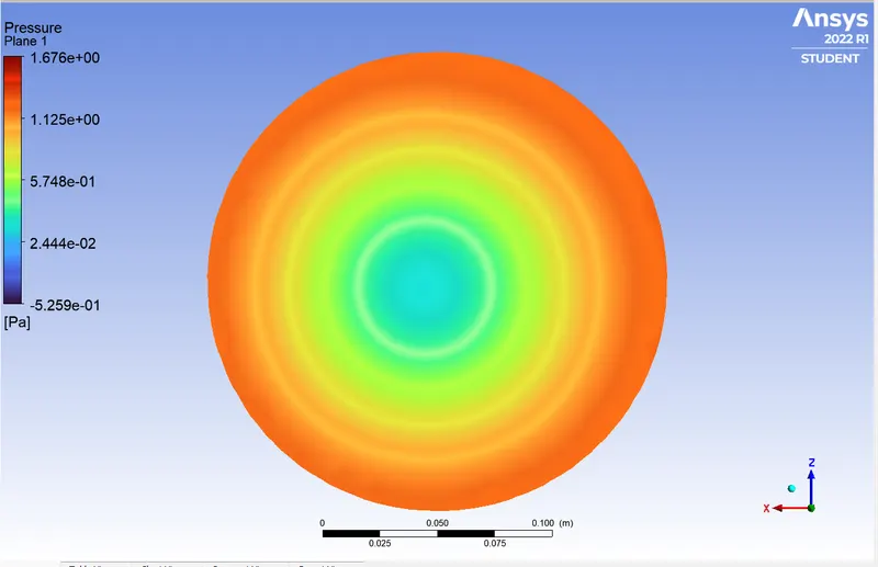
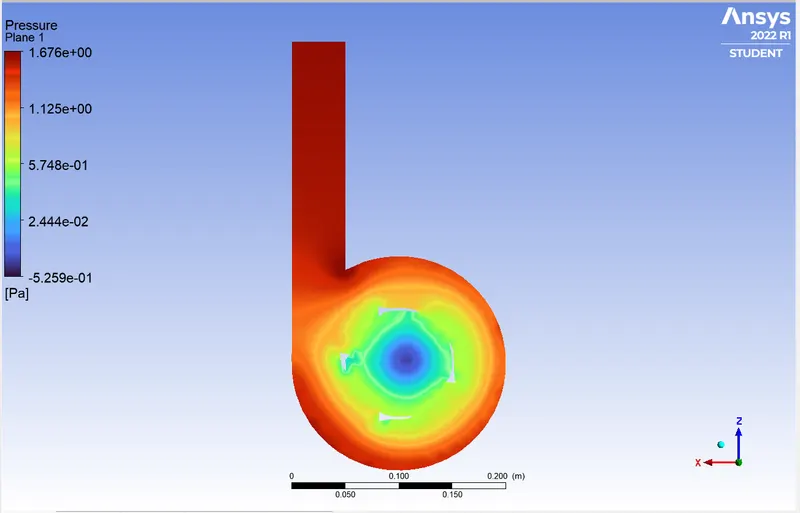
v = 1 m/s
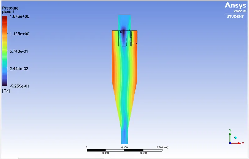
Total Pressure: 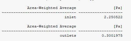
Pressure Drop = 2.25 - 0.3 `implies` 1.95 Pascal
DPM Tracking:
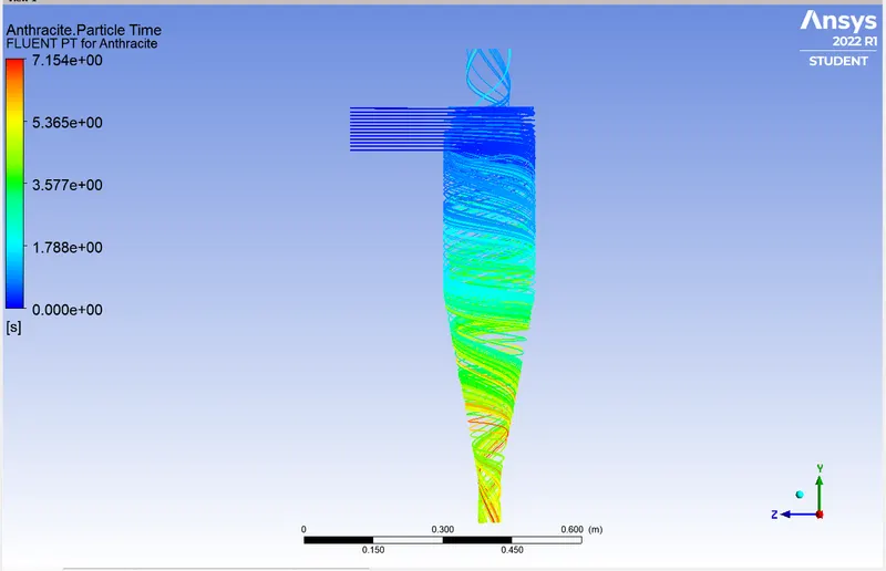

Separation Efficiency = 74/91 * 100 `implies` 81.31 %.
v = 2 m/s:
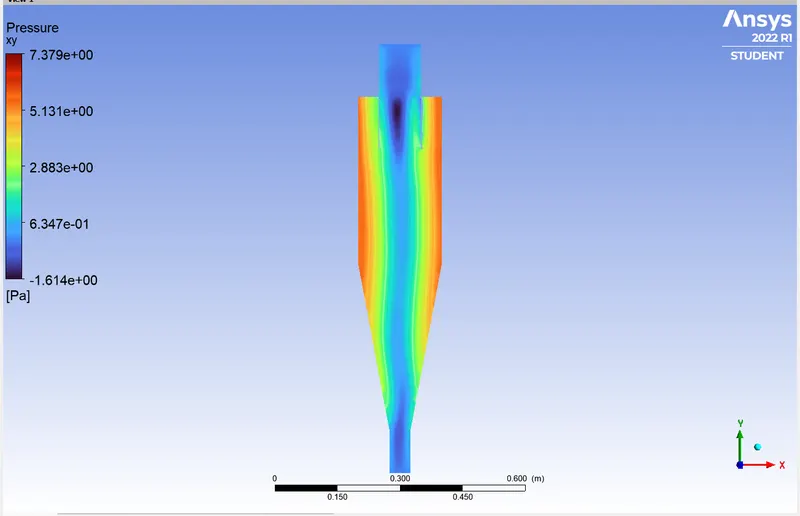
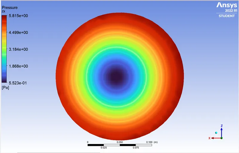
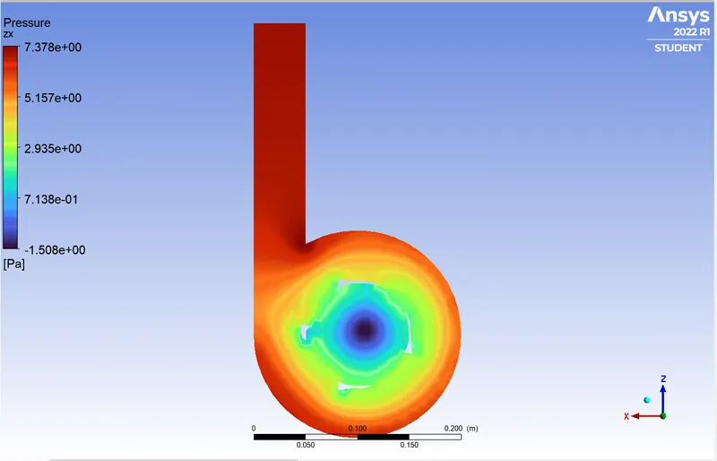
Pressure Profile:
Total Pressure = 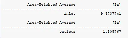
Pressure Drop = 9.57 - 1.3 `implies` 8.27 Pascal
DPM Tracking:
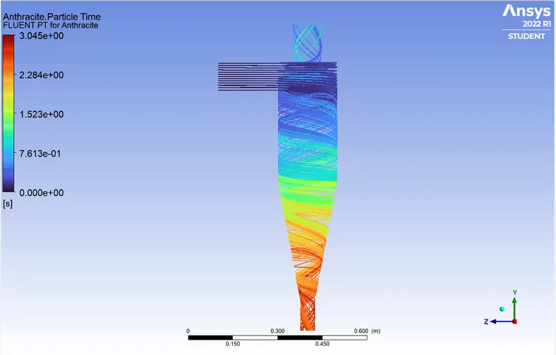

Separation Efficiency = 60/91 `implies` 65.93 %
v = 3 m/s:
Pressure Profile:
Total Pressure:
Pressure Drop = 22.14 - 3.03 `implies` 19.11 Pascal
DPM Tracking:
Separation Efficiency = 50/91 * 100 `implies` 54.94 %.
v = 4 m/s:
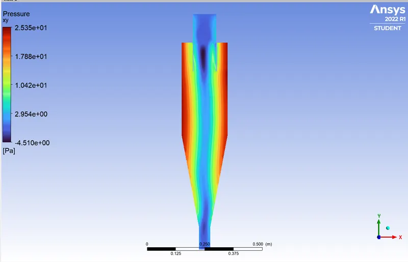
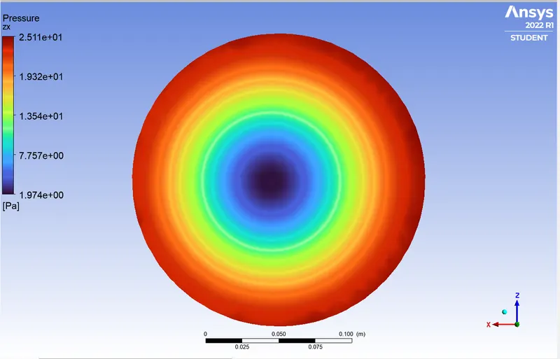
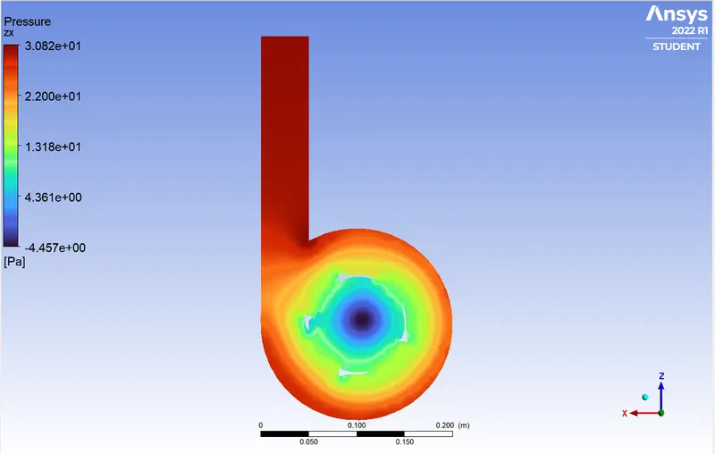
Total Pressure: 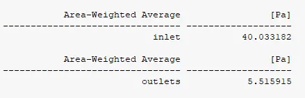
Pressure Drop = 40.03 - 5.51 `implies` 34.52 Pascal
DPM Tracking:
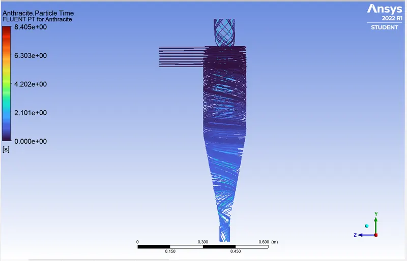

Separation Efficiency = 54/91 `implies` 59.93 %
v = 5 m/s
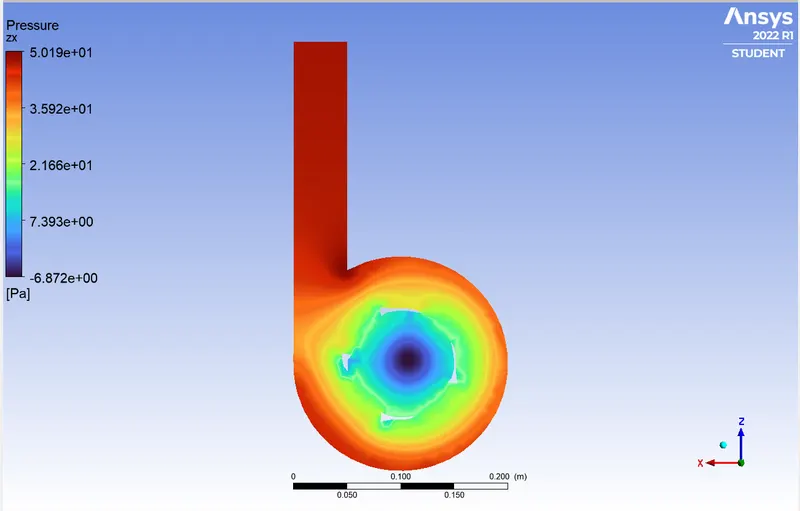
Pressure Profile:
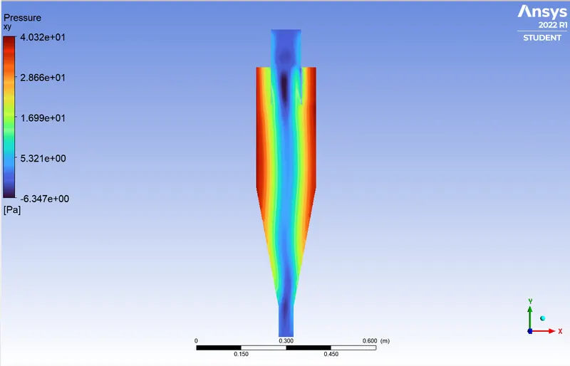
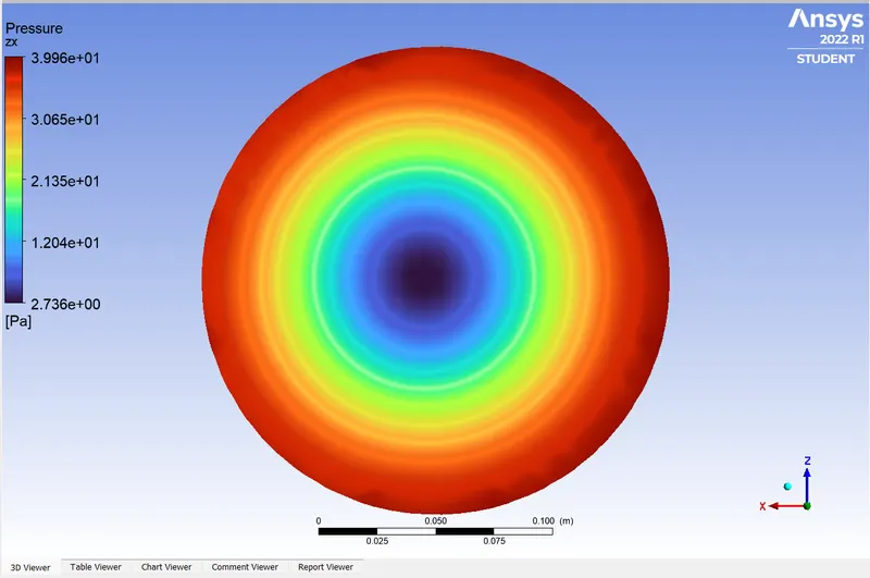
Total Pressure: 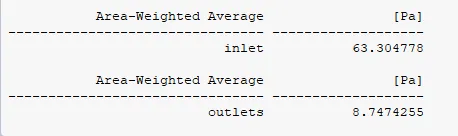
Pressure Drop = 63.30 - 8.74 `implies` 54.55 Pascal
DPM Tracking:
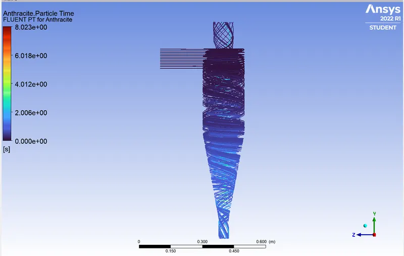

Separation Efficiency = 57/91 `implies` 62.63 %
CONCLUSION:
| Particle Size(µm) | Separation Efficiency (%) |
| 1 | 72.52 |
| 2 | 72.52 |
| 3 | 75.82 |
| 4 | 67.03 |
| 5 | 54.94 |
| Particle Size(µm) | Velocity(m/s) | Pressure Drop(Pascal) | Separation Efficiency (%) |
| 5 | 1 | 1.95 | 81.31 |
| 5 | 2 | 8.27 | 65.93 |
| 5 | 3 | 19.11 | 54.94 |
| 5 | 4 | 34.52 | 59.93 |
| 5 | 5 | 54.55 | 62.63 |
Following inferences can be drawn:
- There exists an optimum flow velocity for a particular particle size for which the efficiency is maximum.
- Particle Size doesn't affect the pressure drop.
- Near the wall region, where the outer vortex is formed, the pressure is higher. The creation of a low-pressure area at the centre of the cyclone separator as a result of higher pressure along the wall causes lighter particles to escape from the top outlet and heavier particles to gather at the bottom outlet.
- As we increase the velocity, the pressure drop increases and as a result heavier particles also escape by getting pulled in the central vortex due to high pressure gradient.
- However, after a certain threshold, the heavier particles start getting trapped again, this could be due to high kinetic energy of the particles due to high velocity, to comment on this further study with more velocity variation might be required