Week 8 - Simulating Cyclone separator with Discrete Phase Modelling
Aim:
To perform analysis on cyclone seperator and calculate the seperation efficiency and pressure drop.
Objective:
Our objective is to simulate for the given cyclone simulator model with anthrecine suspended particle in air medium. We simulate for the given fluid by varying the velocity from 1 m/s to 5 m/ and keeping the partical size as constant 5`mu`. And for other case we have the the velocity cinstant at 3 m/s and size changing from 1 `mu` to 5 `mu`.
Introduction:
DPM -
Discrete Phase Model is a subsection to Multiphase flows. A discrete phase model (DPM) is used when the aim is to investigate the behavior of the particles from a Lagrangian view and a discrete perspective. The difference between the Lagrangian and the Eulerian view is that fluid behavior in the Lagrangian view is examined based on particle tracking of a particulate flow; Whereas fluid behavior is considered in the Eulerian view based on the assumption of a finite volume element in the fluid flow path. Applications of DPM ,
- Calculation of the discrete phase trajectory using a Lagrangian formulation that includes the discrete phase inertia, hydrodynamic drag, and the force of gravity, for both steady and unsteady flows
- Prediction of the effects of turbulence on the dispersion of particles due to turbulent eddies present in the continuous phase
- Heating/cooling of the discrete phase
- Vaporization and boiling of liquid droplets
- Combusting particles, including volatile evolution and char combustion to simulate coal combustion
- Droplet breakup and coalescence
Cyclone Seperator -
Cyclone Seperator is a simplest device implemented for removing a suspended particles in any fluid only by means of vortex seperation. they creat what called centrifugation, a driving force behind the cyclone seperator is a centrifugal force and the difference between the specific gravity between the carrier fluid and the particle. In the cyclone created the air or gas containing the suspended particles is forced along its tangential axis ,a helical flow pattern is setup within the chamber. The centrifugal force causes the particles to migrate outside the chamber by falling to the bottom exit of the chamber and the clean air moves up and exits the chamber. Since this chamber is used to seperate finer particles the bigger particles are filtered before introducing to the chamber. Their simple design , low maintenance cost and low cost makes them as ideal pre-cleaners for more expensive control devices. Their collective effictivness can reach up to 99% for particles bigger than 5`mu`and could handel highly contaminated flows.
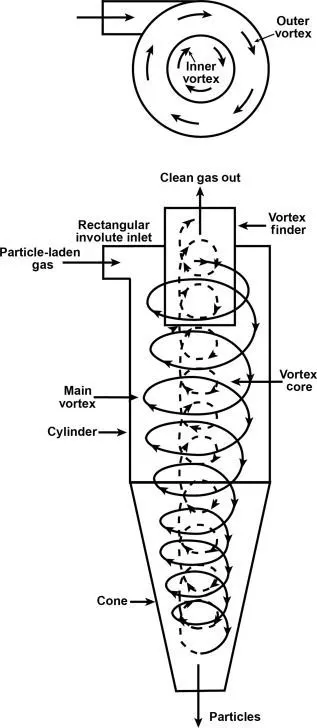
It is easy because this works bassically on the inertias of the fluid particals and the gravity. What happens is the heavier and lighter particles are seperated on basis of their inertia and mass. The lighter particals have more inertia and less mass compared to the heavier impurity particles suspended in it , the centrifugal force insid will create a spiral motion which carries these particles. The lighter particles follow the upward spiral flow and could easily be carried out of the chamber by the swirl whereas the heavier particles will be of more ineria and could not be easily carried away by the swirl and also being heavier the eventually fall out at the bottom of the chamber and exit. By this way the fluid is filtered. Their effectivness is what is important as an in-accurate prediction will lead to failed cyclone seperator. They are highly recomended for seperating particle size greater than 5`mu`. Therefore the efficiency of cyclone seperator depends on the size of partical,Flow rate,Pressure drop.The disadvantages are it cannot be trusted in seperating highily adhesive particles.Basic industrial usage will be in removal of coal dust in thermal powerplant.
1. Emperical models :
1. LAPPLE MODEL
This model was developed based on force balance without considering the flow resistance. Lapple assumed that a particle entering the cyclone is evenly distributed across the inlet opening. The particle that travels from inlet half width to the wall in the cyclone is collected with 50% efficiency. The 50% cut diameter is,
`dpc = [(9µb)/(2πNevi (ρp -ρg ))] ^(1/2)`
`Ne = (1/a)(h + ( H - h)/ 2 )`
`ηi = 1/( 1 + ((d pc) / (d pI))^ 2)`
Where,
Ne = No.of Revolutions
`n` = Efficiency of collection of particles
2. LI AND WANG MODEL :
This model includes particle bounce or re-entrainment and turbulent diffusion at the cyclone wall. A two-dimensional analytical expression of particle distribution in the cyclone is obtained. Li and Wang model was developed based on the following assumptions:
• The radial particle velocity and the radial concentration
profile are not constant, for uncollected particles within the
cyclones.
• Boundary conditions with the consideration of turbulent
diffusion coefficient and particle bounce re-entrainment on
the cyclone wall are:
`c(r, θ) =(c0(rw− rn) exp{−λ[1/(K (1+n))*r^(1+n)]})/(rn to rw int exp{[1/(K (1+n))*r^(1+n)]} dr`
`k = ((1-n)(ρp -ρg )d^2Q )/(18µb(rw ^(1-n) - rn^(1-n ))`
`λ = ((1-α)k*(Ww))/ ((Dr) rw^n))`
The resultant expression of the collection efficiency for particle of any size is given as,
`ηi = 1 - exp {-λθ1}`
and `θ1 = 2π (S + L) / a`
3. KOCH AND LICHT MODEL
This is a collection theory recognized the inherently turbulent nature of cyclones and the distribution of gas residence times within the cyclone. G is a factor related to the configuration of the cyclone, n is related to the vortex and τ is the relaxation term.
`ηi= 1 − exp{−2[(GτiQ)/(D^3)(n + 1)]^(0.5/(n+1))}`
and , G`= (8kc)/ ((ka)^2 (kb)^2)`
`n = 1 −{1 −((12D)^0.14)/(2.5) }{(T + 460)/530}`
`τi = (ρpd^ 2 pI)/( 18 µ)`
4. IOZIA AND LEITH MODEL
This model which is developed based on force balance. The model assumes that a particle carried by the vortex endures the influence of two forces: a centrifugal force, Z, and a flow resistance, W. Core length, zc , and core diameter, dc , are given as,
`zc = (H - S) - [(H-S)/((D / B) -1)] (((dc)/B) - 1) when ( dc > B)`
`zc = (H - S) when (dc< B)`
`dc = 0.47 ((ab)/ D^2)^ -0.25 ((De)/ D) ^1.4`
The collection efficiency ηi of particle diameter dpi can be calculated from,
`ηi = 1 /((1+((dpc) / (dpI)))^beta`
Procedure:
Geomentry:
We import the solifd model from the database into spaceclaim. Then we use prepere option to extract the volume where the fluid intrects.
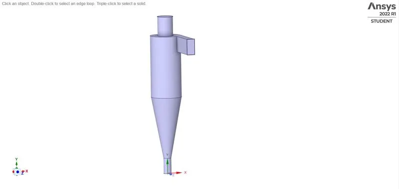
The dimentions of the model are as follows,
Inlet = 50 mm `*` 100 mm
Outlet Top = 100 mm
Outlet Bottom = 50 mm
Height of Cyclone Seperator = 1000 mm
Mesh:
Since the default mesh size is larger we decrease the mesh size to 10 mm. Also the Cartisian method is used for mesh distribution so that the mesh cells are uniform to the Global cartesian. It is adsived to decrease the mesh size as the no.of particles tracked by the solver depends on it . The smaller the mesh size the larger the no.of particles tracked from the inlet.
No.of Elements = 52388
Size = 10 mm
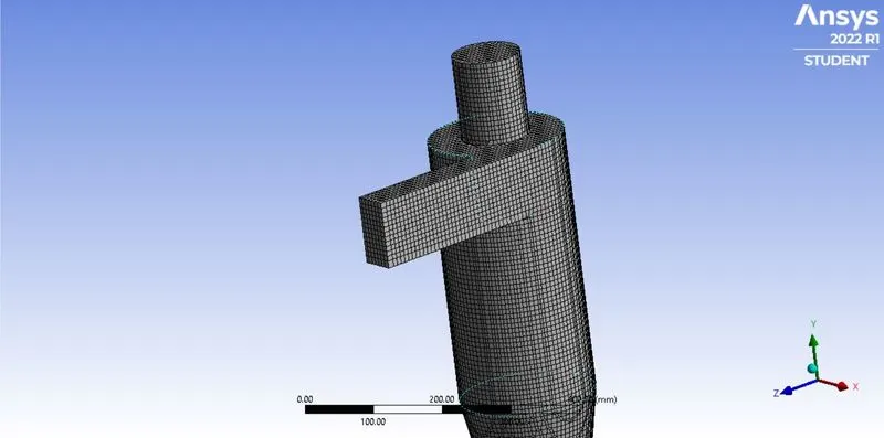
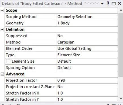
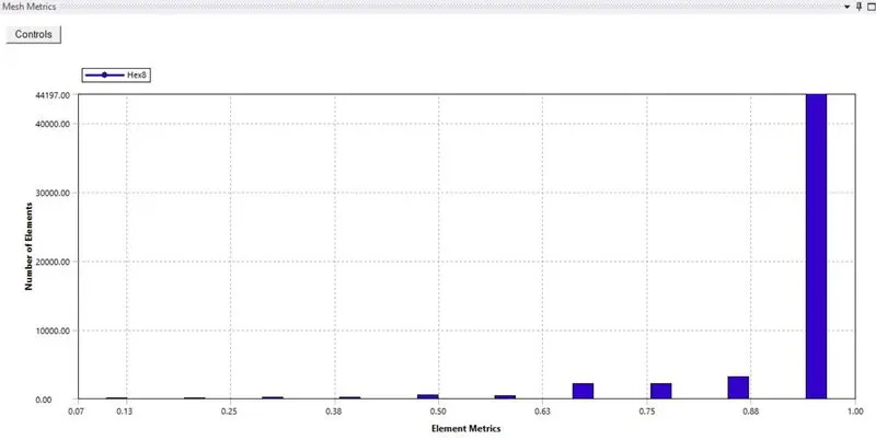
Minimum quality for this meshed model is 13%.
Setup:
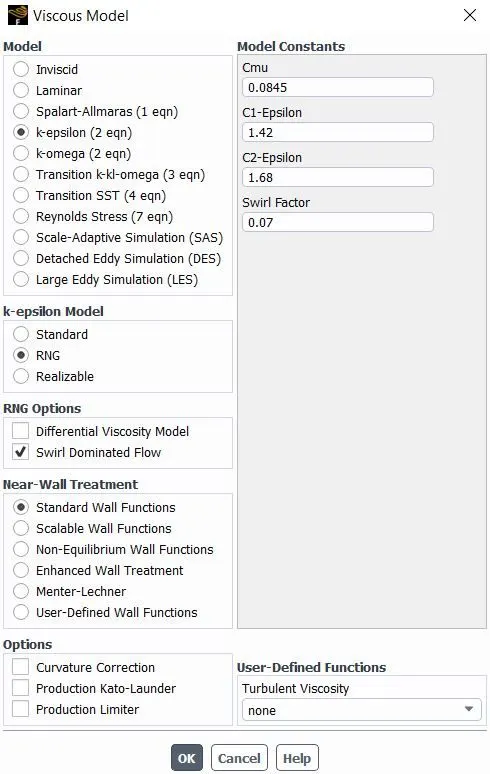
For setting up the model we first mention the gravity force which is important for partical seperation along -Y axis. For the setting up the model we use the k-epsilon model and we use RNG model under this. Since,the RNG approach, which is a mathematical technique that can be used to derive a turbulence model similar to the k-epsilon, results in a modified form of the epsilon equation which attempts to account for the different scales of motion through changes to the production term. Since swirl is involved we also check the swril condition.
Next to define for the Discrete Phase Model (DPM). There are two two types of flow ,
- Coupled flow - In this case the discrete flow influences the contnious phase.
- Un-Coupled flow - There will be no interactions with contnious phase.
In this model we choose Coupled flow. Then we check for the update DPM sources, so we can calculate the partical source terms at every itereations and it is necessary for unsteady flows. We give the Max. Number of timesteps so that we say the solver till the maximum steps the solver can track each particles inside the chamber. Sometimes the particels just re-circulates inside the chamber so we cna neglect when it surpasses this value.
Time Step = Specific length Scale / (Velocity of Discrete Phase * Velocity of Contnious Phase)
Time Step = 1/step length Factor
Therefore , larger the Specific length scale the accurate the solution.
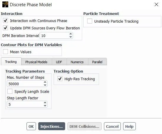
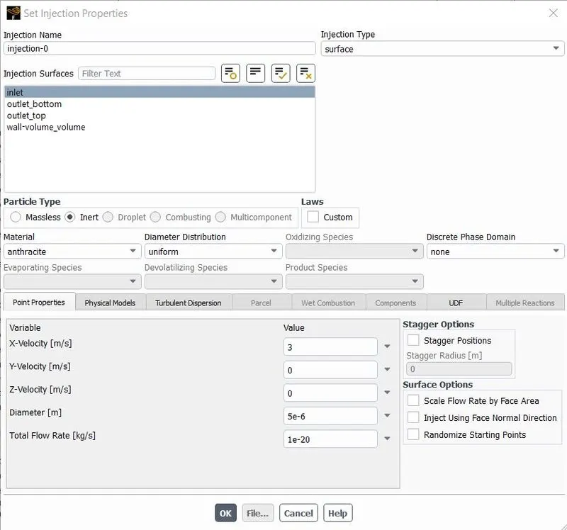
Further we create the new DPM under injection. We chose particle type as anthracite and selected as surface inlet , then we iterate the solution for different values of velocity and particle diameter.
We set the noundary conditions as below for the DPM criteria.
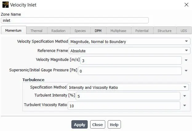
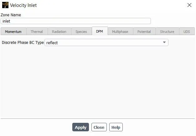
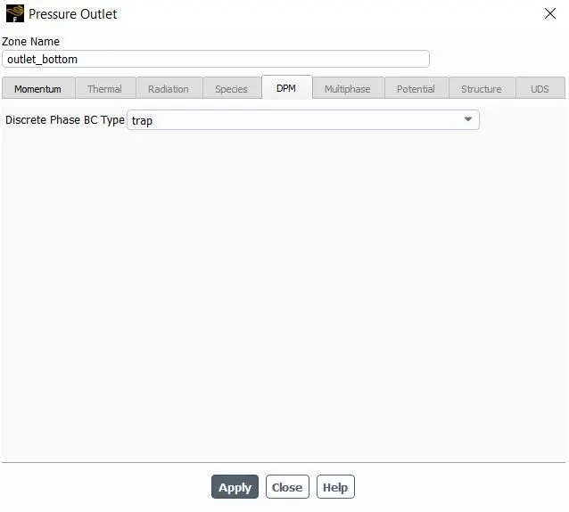
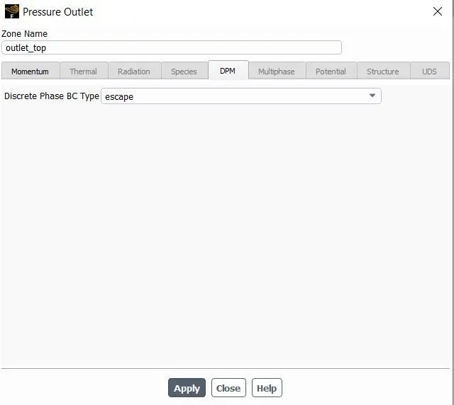
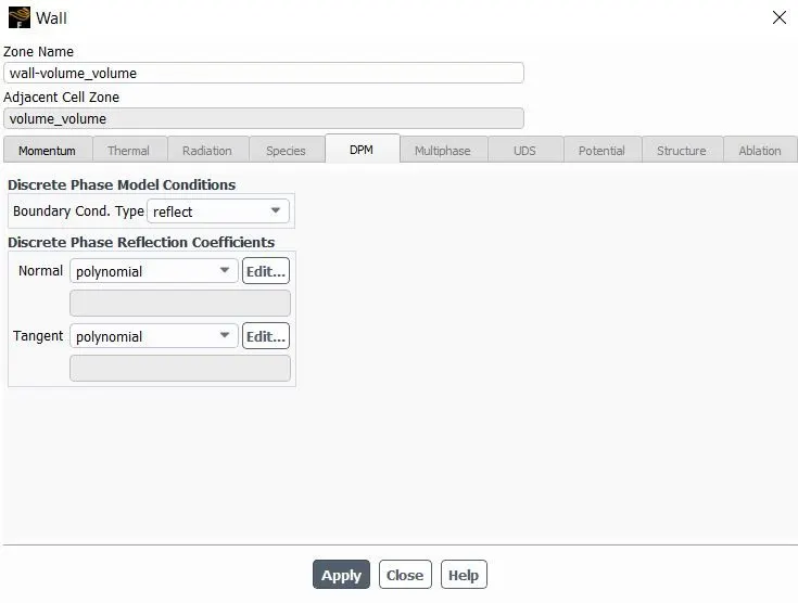
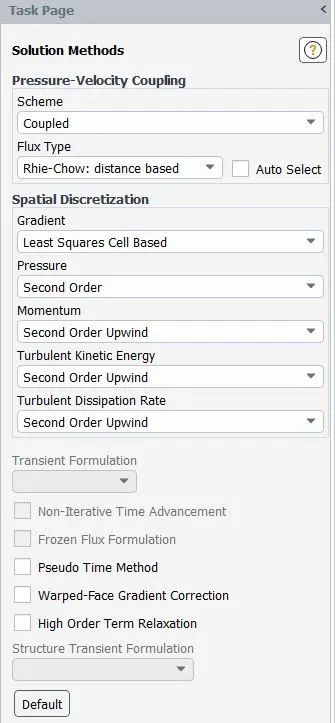
For Solution methods we choose COUPLED model and Second Order Upwind.
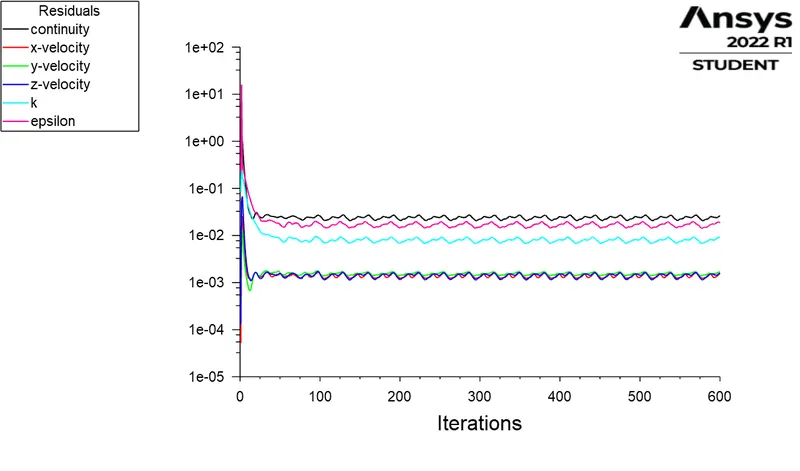
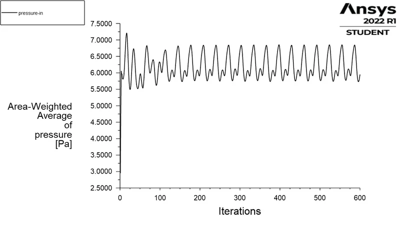
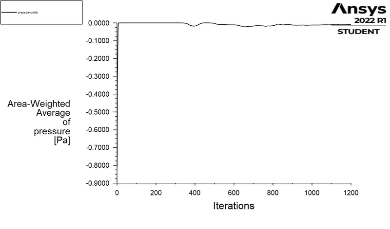
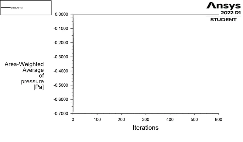
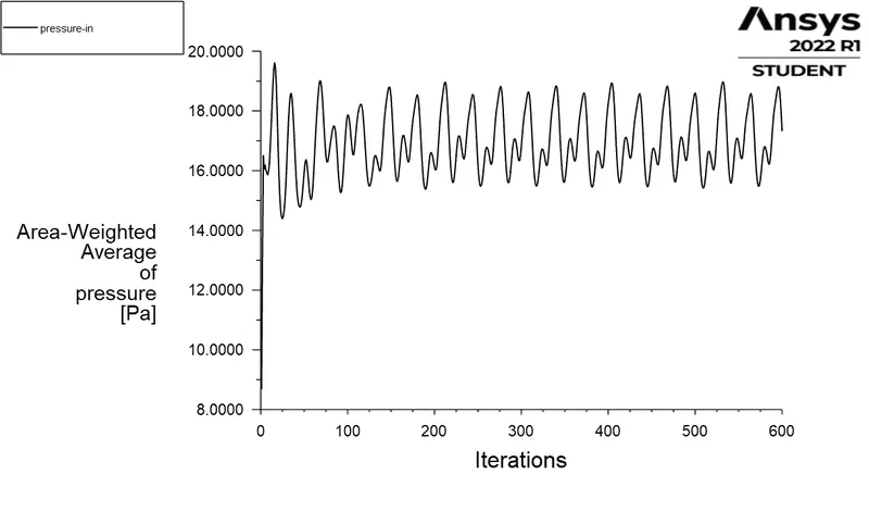
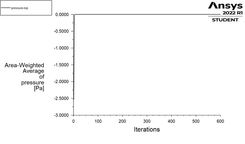
For calculating the pressure drop we created average pressure at inlet and outlet bottom and plotted the graph.
We choose standard inilization from inlet
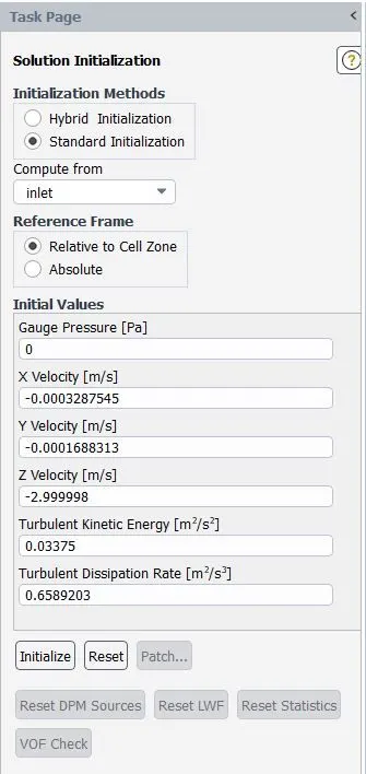
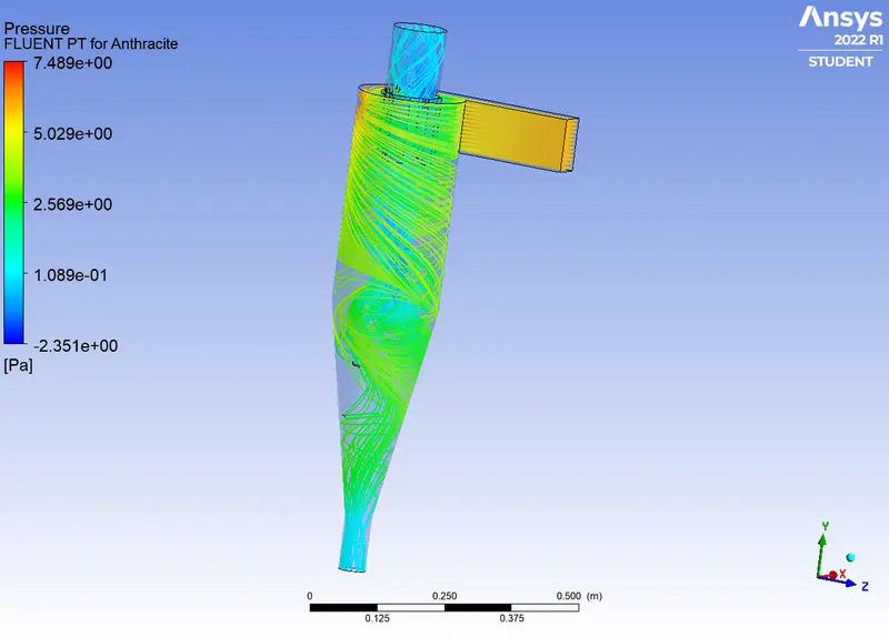
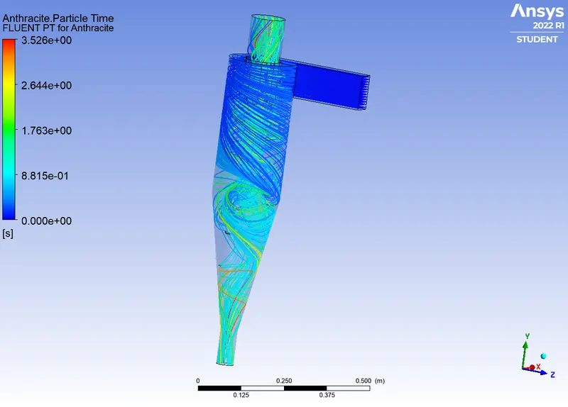
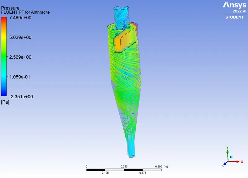
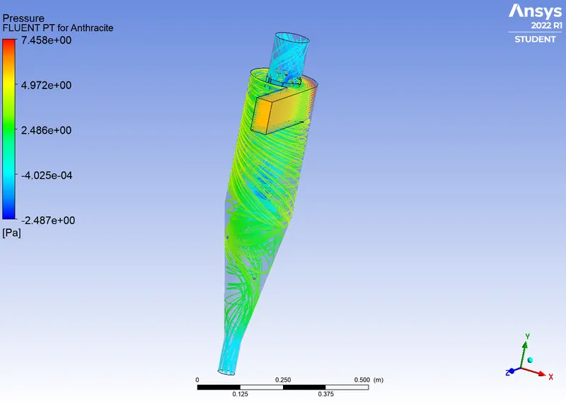
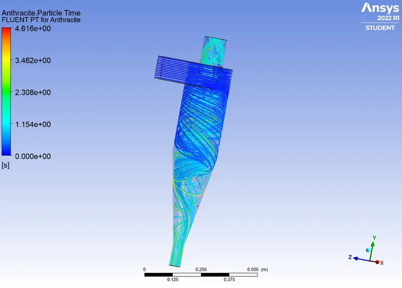
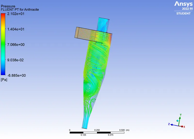
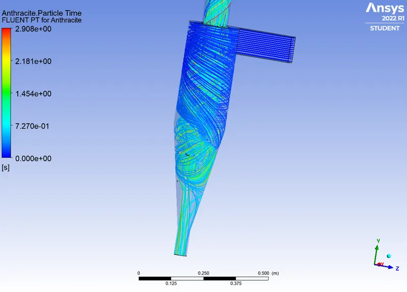
After the solution converged we Exported the solution partical data to CFD Post to visuavalize the results.
Results:
2.
Case 1 -
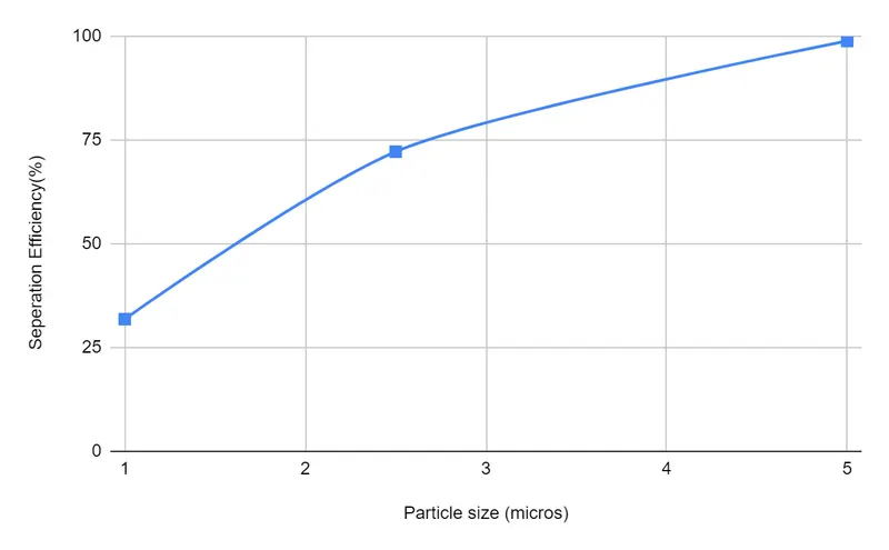
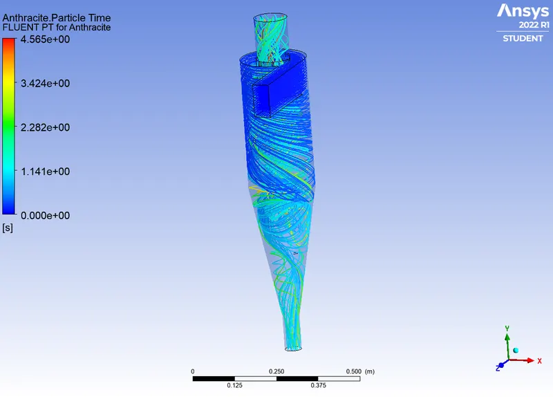
For partical size 1 `mu`, 2.5 `mu` and 5 `mu` and velocity of flow and partical at 3 m/s.
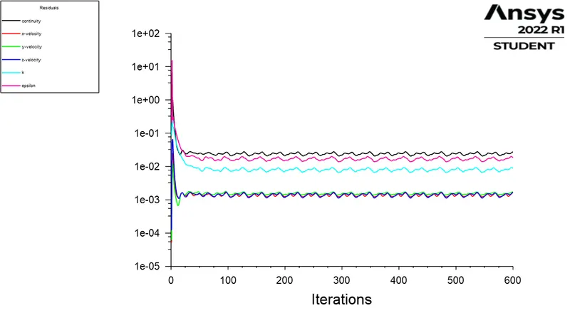
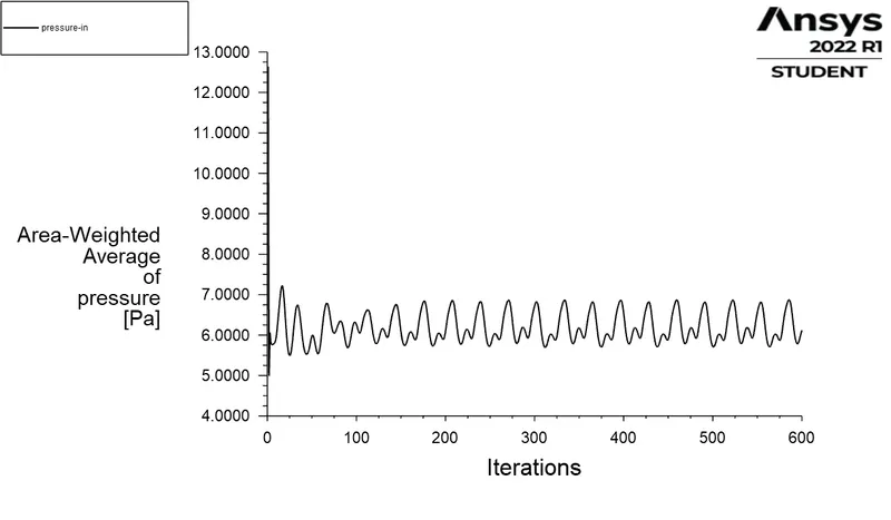
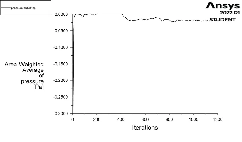
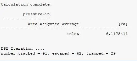
Pressure drop = [Pressure Inlet - Pressure Outlet ]
= 6.3241
Seperation Efficiency = (29/91) * 100
= 31.87 %
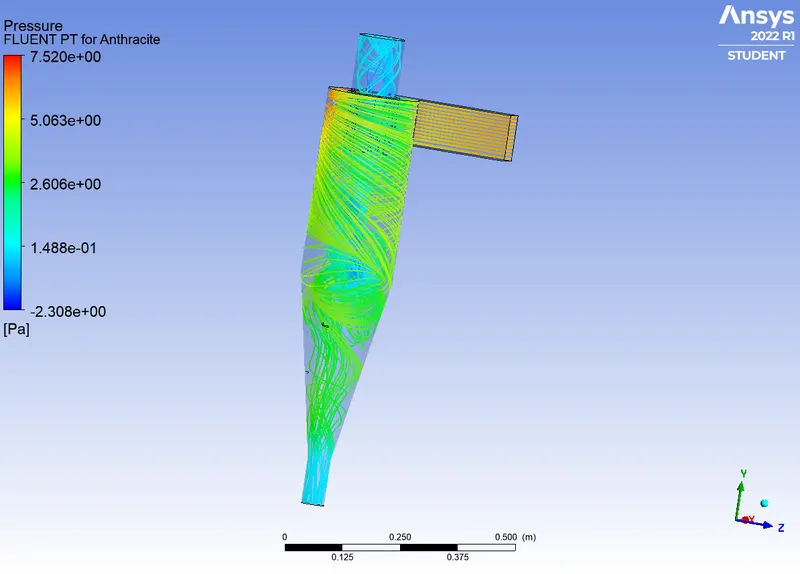
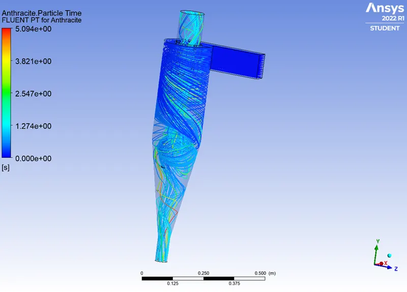
Case 2 -
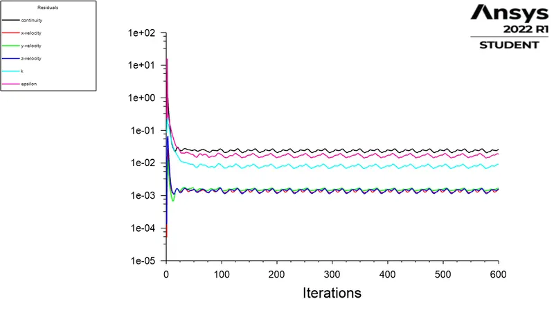
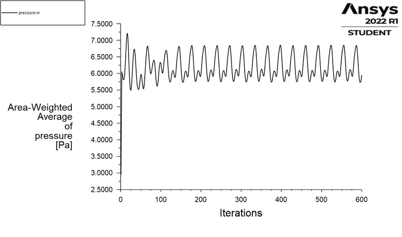
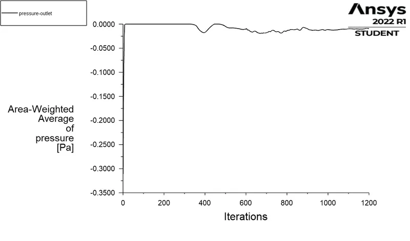
Pressure drop = [Pressure Inlet - Pressure Outlet ]
= 6.25386 pa
Seperation Efficiency = (29/91) * 100
= 31.87 %
Case 3 -
| S.No | Velocity (m/s) | Partical Size (`mu`) | Particles Tracked | Particles Trapped | Particles Escaped | Seperation Efficiency(%) | Pressure Drop (pa) |
| 1 | 3 | 1 | 91 | 29 | 62 | 31.86 | 6.3241 |
| 2 | 3 | 2.5 | 91 | 65 | 26 | 72.22 | 6.2538 |
| 3 | 3 | 5 | 91 | 90 | 1 | 98.90 | 6.2316 |
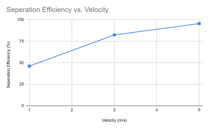
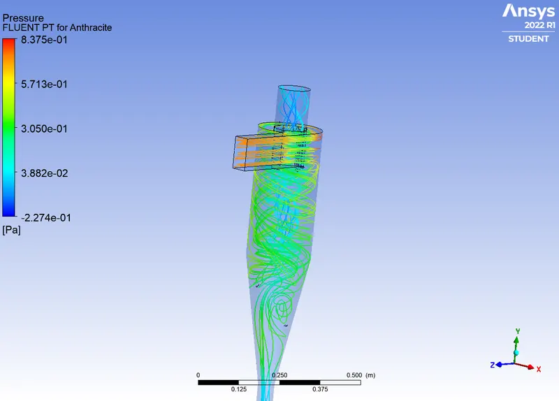
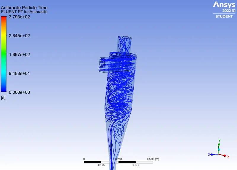
For the below case we have the condition of partical and flow velocity as 1 m/s, 2.5 m/s ,and 5 m/s with partical size 5 `mu`.
3.
Case 1-
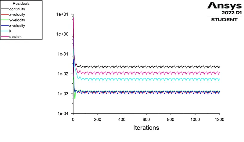
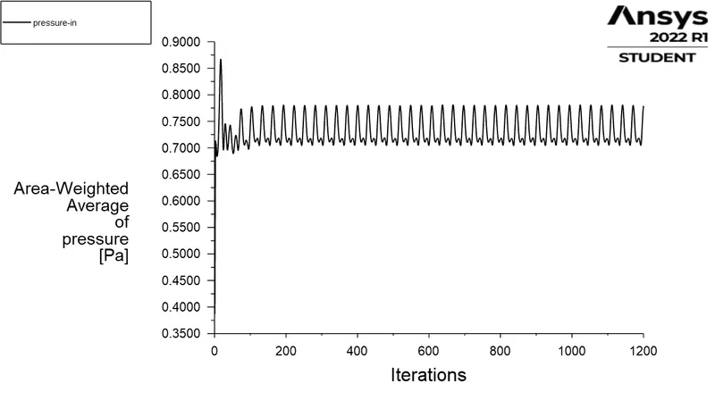
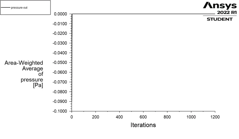
Case 2 -
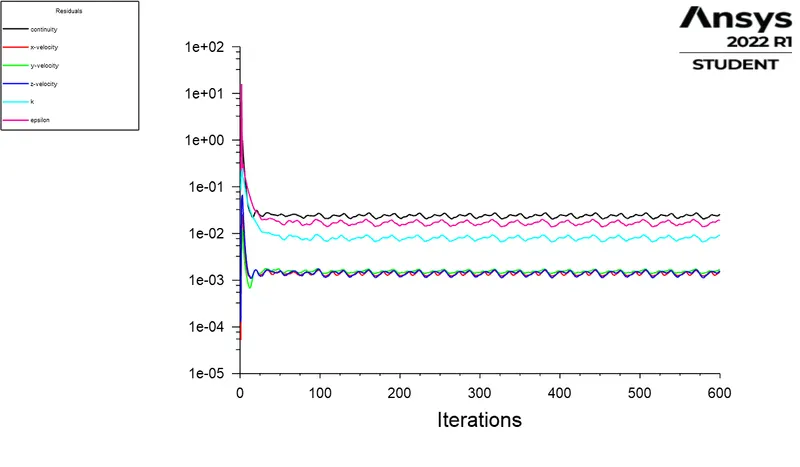
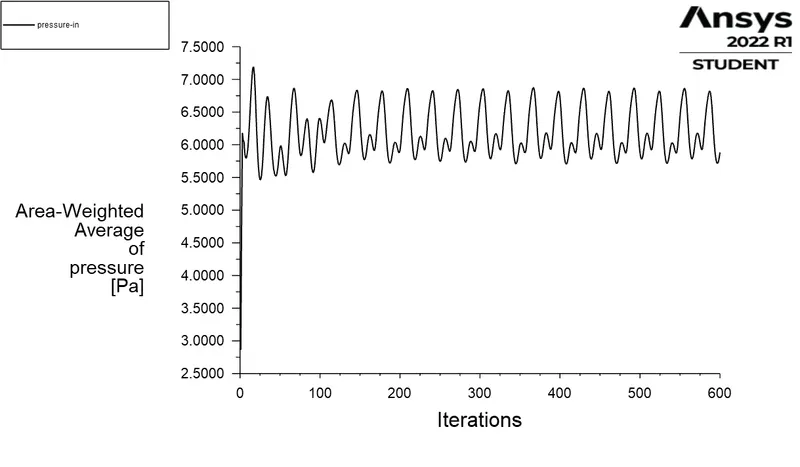
Case 3 -
| S.No | Velocity (m/s) | Partical Size (`mu`) | Particles Tracked | Particles Trapped | Particles Escaped | Seperation Efficiency (%) | Pressure Drop (pa) |
| 1 | 1 | 5 | 91 | 42 | 48 | 46.15 | 0.7362 |
| 2 | 3 | 5 | 91 | 75 | 16 | 82.41 | 6.1120 |
| 3 | 5 | 5 | 91 | 87 | 4 | 95.60 | 16.7235 |
Summary:
From the results and as discussed earlier the lighter particles gains energy in form of K.E and escapes at top and heavier particles escapes from the bottom. And to make this process easier we always knowm that a local low pressure region will be created at the center of the cyclone and this low pressure region acts as a carrier and sucks the lighter particles above. The total pressure drop is a reason of wall friction , energy dissipation by swirl. From the table we can fuurther plot the graph for better understanding on how varying parameters affects the efficeincy as it is crutial for the effectivness of the seperator. The below shown gtreph is for Different velocities and particle diameters respectively. As we can obseerve in both cases a near 100% efficiency is thus acheived. In the second graph we can clearly see the energy losses as the inlet velocity increases the pressure drop also increases. And as for the first table the pressure drop almost always remains the same so we can conclude that the change in particle diameter does not affect the pressure drop.