Simulating Cyclone separator with Discrete Phase Modelling
# Abstract:
Parameters affecting cyclone separator efficiency are studied by simulating the flow with varying particle size and varying inflow velocity. It is found that velocity & particle size has the most prominent[1-2] effect on efficiency hence only these two factors are examined in detail. The simulations are carried out with commercially available CFD tool ANSYS® Fluent® 2021 R2 Student version.
# Introduction:
A cyclone separator is used for separating particulate matter from gas streams. These devices are low cost & easy to maintain and hence are widely used in industrial processes.
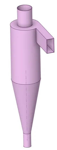
Cyclones separators are basically centrifugal separators, they consist of an upper cylindrical part referred to as the barrel and a lower conical part referred to as a cone. They simply transform the inertia force of gas-particle flows to a centrifugal force by means of a vortex generated in the cyclone body. The particulate matter is caught in a cyclone away from the center and eventually falls down into the collecting bin attached to the bottom outlet. The clean gas escapes through the top outlet.
# Emperical models used for cyclone efficiency:
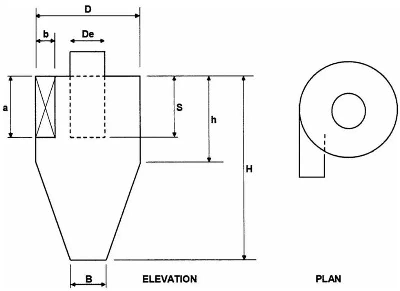
Tangential cyclone configuration
Iozia and Leith Model
This model is developed based on force balance. The model assumes that a particle carried by the vortex endures the influence of two forces: a centrifugal force, Z, and flow resistance, W. The collection efficiency `eta_i` of particle diameter `d_("pi")` can be calculated from
`eta_i = 1/(1+(d_(pc)//d_("pi")))`
`beta` is an expression for slope parameter derived based on the
statistical analysis of experimental data of a cyclone.
Li and Wang Model
The Li and Wang [3] model include particle bounce or re-entrainment and turbulent diffusion at the cyclone wall. A two-dimensional analytical expression of particle distribution in the cyclone is obtained. Li and Wang's model was developed based on the following assumptions:
- The radial particle velocity and the radial concentration profile are not constant for uncollected particles within the cyclone.
- Boundary conditions with the consideration of turbulent diffusion coefficient and particle bounce re-entrainment on the cyclone wall are:
`c = c_0," at " theta=0`
`D_r(del c)/(delr)= (1-alpha)wc," at "r=D//2`
- The tangential velocity is related to the radius of cyclone by: `u R^n =` constant
The concentration distribution in a cyclone is given as:
`c(r,theta)=( c_0(r_w-r_n)exp{-lambda[1/(K(1+n))r^(1+n)] }) /( int_(r_n)^(r_w) exp{1/(K(1+n))r^(1+n) } dr)`
where,
`K = ((1-eta)(rho_p-rho_g)d^2Q)/ (18mub(r_w^(1-n) -r_n^(1-n) )`
and
`lambda=((1-alpha)Kw_w )/ ( D_r r_w^n )`
The resultant expression of the collection efficiency for particle
of any size is given as,
`eta_i = 1-exp{-lambdatheta_1}`
where
`theta_1=2pi(S+L)//a`
Koch and Licht Model
Koch and Licht's collection theory recognized the inherently turbulent nature of cyclones and the distribution of gas residence times within the cyclone. Koch and Licht described particle motion in the entry and collection regions with the additional following assumptions:
- The tangential velocity of a particle is equal to the tangential velocity of the gas flow, i.e. there is no slip in the
the tangential direction between the particle and the gas. - The tangential velocity is related to the radius of the cyclone by: `u R^n =` constant.
A force balance and an equation on the particles collection yields
the grade efficiency `eta_i`,
`eta_i = 1- exp {-2[( Gtau_iQ )/D^3 (n+1)]^(0.5//(n+1))}`
where
`G = (8K_c)/(K_a^2K_b^2)`
`n = 1-{ 1-(12D)^0.14/2.5}{ (T+460)/530 }^0.3`
`tau_i=(rho_pd_("pi")^2)/(18mu)`
G is a factor related to the configuration of the cyclone, n is
related to the vortex and τ is the relaxation term.
Lapple Model
Lapple model was developed based on force balance without considering the flow resistance. Lapple assumed that a particle entering the cyclone is evenly distributed across the inlet opening. The particle that travels from the inlet half-width to the wall in the cyclone is collected with 50% efficiency. The semi-empirical relationship developed by Lapple to calculate a 50% cut diameter, `d_(pc)`, is
`d_(pc)=[ (9mub)/(2piN_ev_i(rho_p-rho_g))) ]^(1/2)`
where Ne is the number of revolutions
`N_e=1/a[h+(H-h/2)]`
The efficiency of collection for any size of particle is given by
`eta_i = 1/(1+(d_(pc)//bard_("pi") )^2)`
# Computational domain:
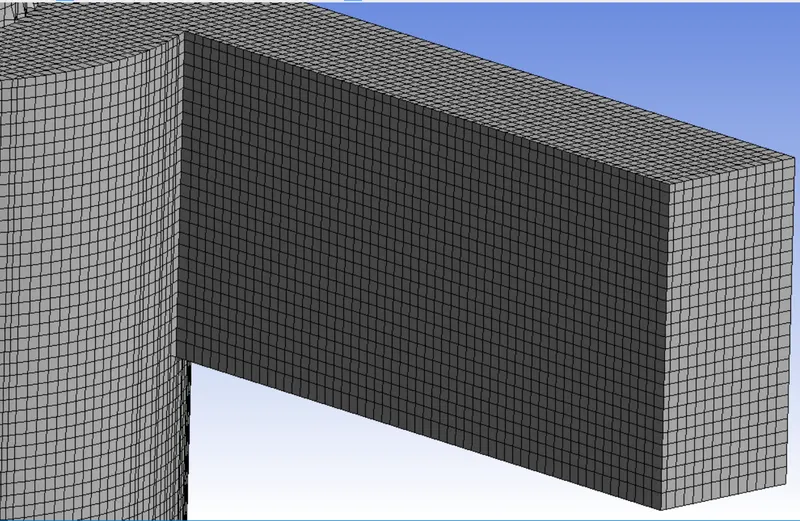
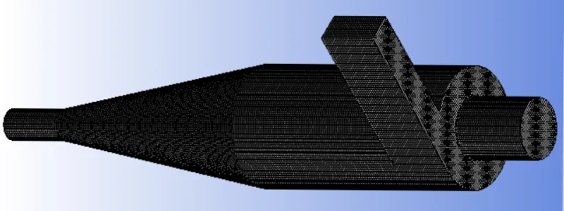
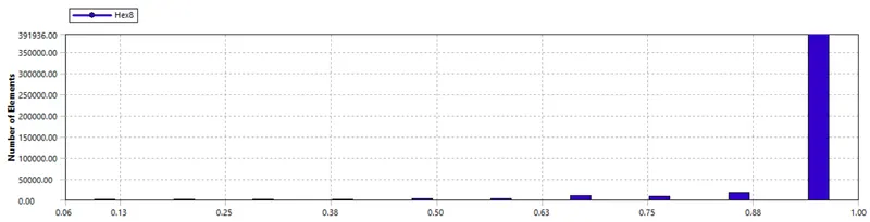
- For accurate flow prediction, the high-quality Cartesian mesh is used. The mesh is fine with an element size of 5mm as shown below.
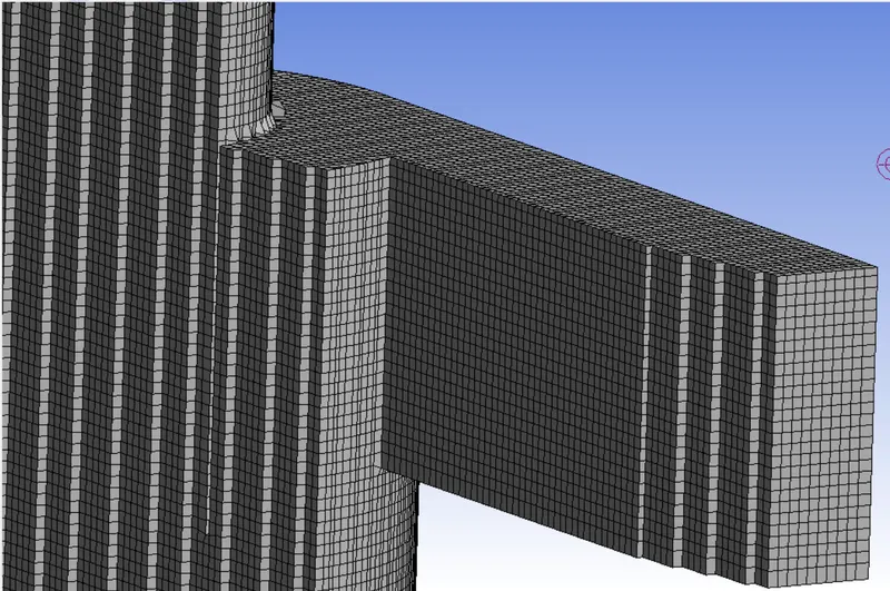
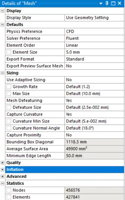
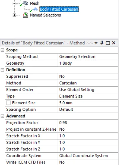
- The other mesh settings are as below.
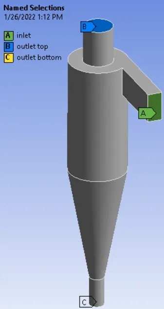
Named selections
Named selections are made so that fluent can apply wall Boundary conditions on these surfaces.
# Numerical model:
Turbulence model:
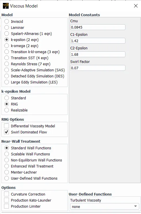
For reduced computational effort RANS-based RNG `k-epsilon` turbulence model is used with standard wall functions for near-wall modeling. This method is derived using a statistical method RNG (Re Normalization Group) and is found to be accurate for swirling flows.
Discrete Phase model:
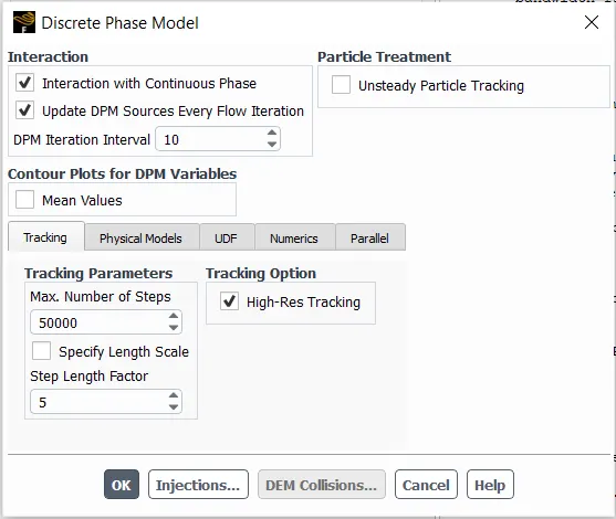
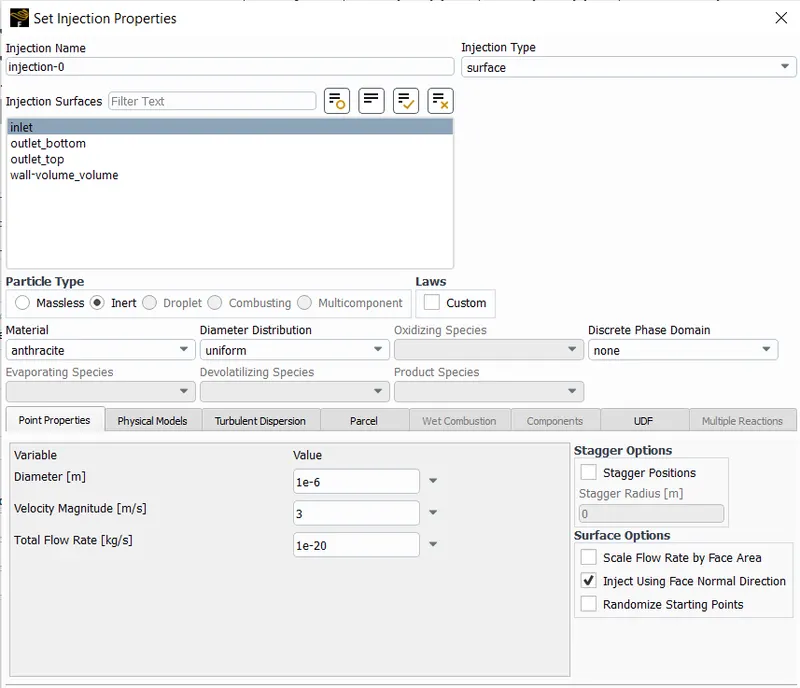
DPM is used for modeling particulate matter in the flow. The particles are injected normally to the inlet face at flow velocity. Since cyclone separators are mainly used to clean the inflow gas the particulate nature is kept inert.
Solution method:
The solution procedure is iterative and is based on coupled scheme for Pressure-Velocity coupling. The discretization is `2^(nd)` order for pressure and `2^(nd)` order upwind for other variables. The gradient is computed using the Rhie-Chow distance-based method. Commercially available CFD tool ANSYS® Fluent® 2021 R2 Student version is used which has a limit of 512,000 cells in the mesh.
# Boundary Conditions:
| Boundary | Momentum B.C. | DPM B.C. |
| Inlet | Velocity inlet, normal to face | Reflect |
| Top outlet | constant pressure outlet | escape |
| Bottom outlet | constant pressure outlet | trap |
| Cyclone walls | Wall, no-slip | - |
# Solver settings:
• The mach no. of flow (5/343= 0.014) is less than 0.3 hence steady-state pressure-based solver is used with gravity enabled (-9.81 m//s^s in Ydir)
• RNG `k-epsilon` model with standard wall treatment is used for capturing turbulence.
• DPM is used and particulate velocity is kept the same as flow velocity (defined in inlet boundary).
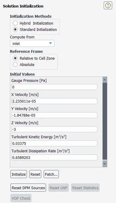
• The simulations were done for 600 iterations after standard initialization.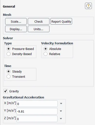
# Results (for `3 m//s` flow & `5 mu m` particles):
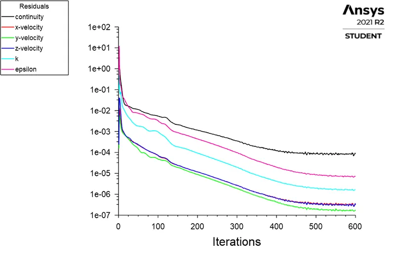
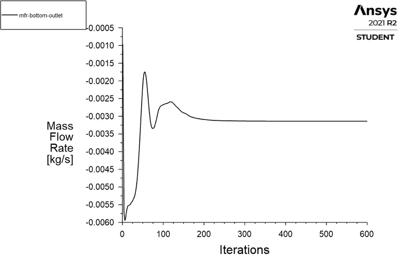
- It can be seen that the mass flow rate converges after about 250 iterations and residuals stop dropping after around 500-550 iterations hence all simulations were done with 600 iterations.
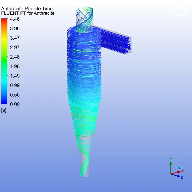
- The particulate flow is also shown. It can be seen that not all particles are trapped as some escape through the upper outlet.
- The results from DPM are also shown.
- The convergence plots and particle trajectory are similar for all other cases hence only DPM results are reported in the next section with pressure contours for cases with varying velocity.

# Post-Processing:
Pressures contours for the constant particulate size of `5 mum`.
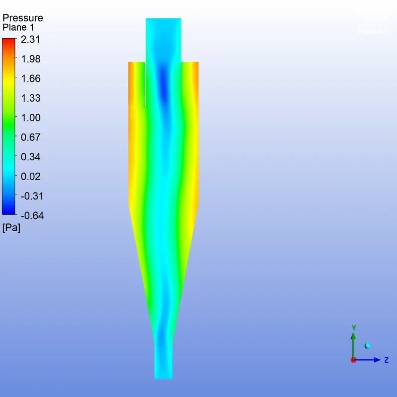
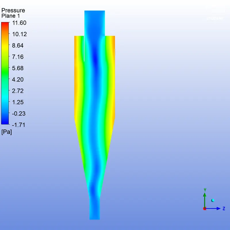
(v = 1 `m//s`) (v = 2 `m//s`)
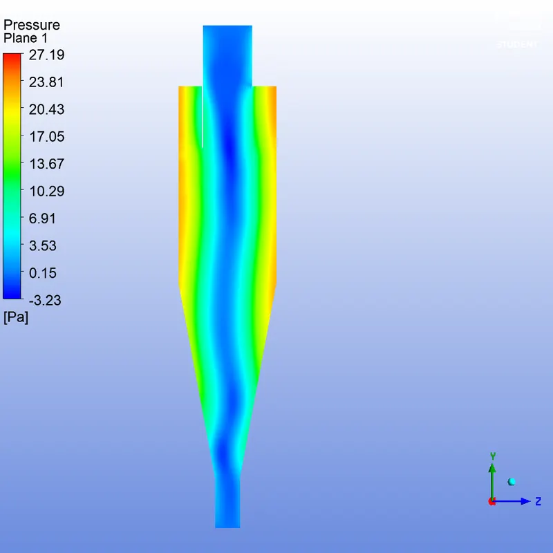
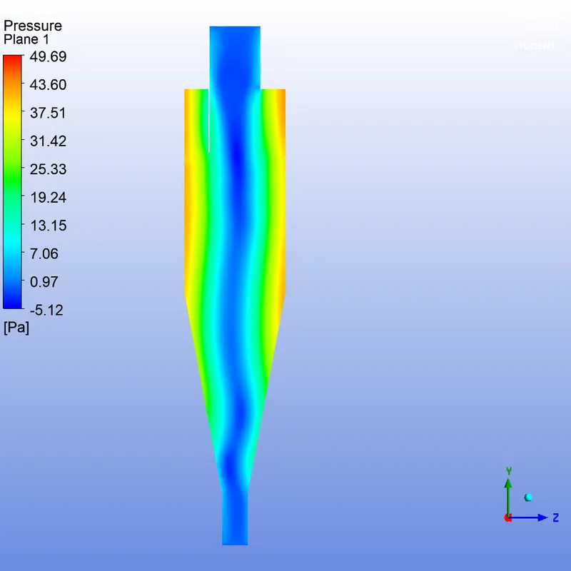
(v = 3 `m//s`) (v = 4 `m//s`)
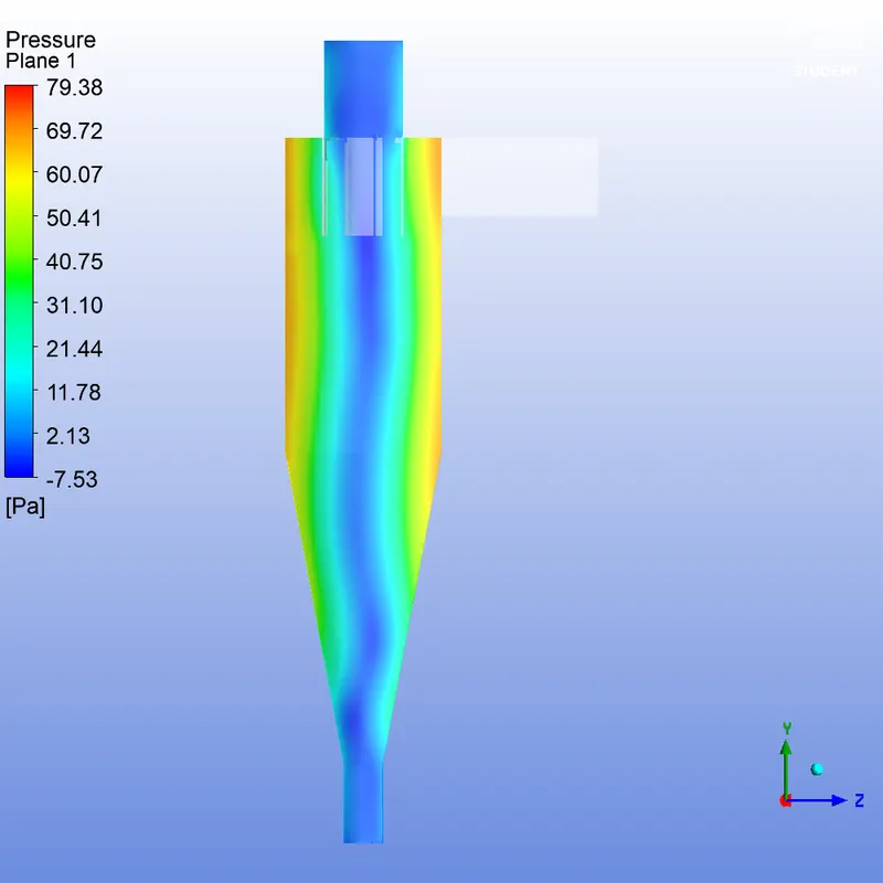
(v = 5 `m//s`)
# Results:
The table below summarizes the simulation results.
| Flow Velocity (`m//s`) | Particle size (`mum`) | Particle inflow | Particles trapped | Efficiency (%) |
| 3 | 1 | 378 | 229 | 60.58 |
| 2 | 378 | 258 | 68.25 | |
| 3 | 378 | 294 | 77.78 | |
| 4 | 378 | 303 | 80.16 | |
| 5 | 378 | 306 | 80.95 |
| Flow Velocity (`m//s`) | Particle size (`mum`) | Particle inflow | Particles trapped | Efficiency (%) |
Pressure drop (Pa) (inlet - bottom outlet) |
| 1 | 5 | 378 | 291 | 76.98 | 2.275 |
| 2 | 378 | 307 | 81.21 | 11.34 | |
| 3 | 378 | 306 | 80.95 | 26.19 | |
| 4 | 378 | 311 | 82.28 | 47.76 | |
| 5 | 378 | 317 | 83.86 | 76.19 |
# Inferences:
- It can be seen that separator efficiency increases with particle size. This is because heavier particles have more inertia & separate easily from the vortex core at the center. The gravity pull is also higher.
- The separator efficiency also increases with flow velocity however, after a certain velocity it seems that the increase in efficiency is not significant.
- Also, the pressure drop increases with velocity so it is better to have a slightly lower efficiency than a significantly higher pressure drop unless the process demands it.
References:
- B. Wang, D.L. Xu, K.W. Chu, A.B. Yu, Numerical study of gas-solid flow in a cyclone separator, Applied Mathematical Modelling,
Volume 30, Issue 11,2006,Pages 1326-1342,ISSN 0307-904XVolume 30, Issue 11,2006,Pages 1326-1342,ISSN 0307-904X. - Gimbun, Jolius & Luqman Chuah, Abdullah & Choong, TSY & Fakhru'l-Razi, A.. (2005). A CFD Study on the Prediction of Cyclone Collection Efficiency. International Journal for Computational Methods in Engineering Science and Mechanics. 6. 161-168. 10.1080/15502280590923649.
- ANSYS Documentation