Flow simulation over a backward facing step in OpenFOAM
# The case :
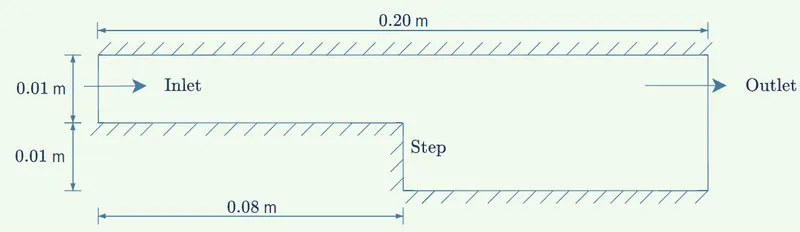
We are going to simulate transient variations in the laminar flow of an incompressible, viscous fluid through a 2D backwards-facing step. Water is chosen as the incompressible fluid which flows from left to right in the setup shown in fig.(1). Also, we are going to use a non-graded mesh and a graded mesh (grading factor 0.2 near walls) for simulation.
We will set up our case files using OpenFOAM-2012 tutorial Cavity located in,
opt/OpenFOAM/OpenFOAM-v2012/tutorials/incompressible/icoFoam/cavity/by modifying Cavity case files. This is so because the cavity tutorial simulates the transient laminar flow of an incompressible, viscous, Newtonian fluid in a 2D cavity which is the same for our case except that our geometry & mesh are different.
Due to this similarity, we need to modify only some Cavity case files applicable to our case. This makes setting up the case files quick and less tedious. Keeping in mind the future use of tutorial Cavity we will make its copy in our working folder ($FOAM_RUN/bfs) and then apply modifications in the copy so that the original Cavity folder remains intact. To do this, we will use cp command as follows,

# Geometry & Mesh Generation:
Geometry:-
`fig.(1)`
The geometry of the setup is shown in fig.(1). For clarity, the image shows only the side view because the z-dimension is small (`0.001` m) & is not significant as the simulation is 2D.
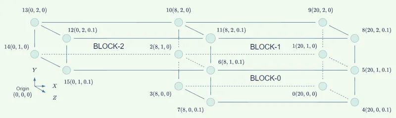
We will divide the geometry into three blocks (numbered 0-1) and number the vertices as shown in fig.(2).
`fig.(2)`
It is possible to use only two blocks for mesh generation but more blocks provide better control over the mesh.
Procedure for Mesh generation (setup-1:No mesh grading):-
- Go to the working folder directory and open blockMeshDict in the system folder with the preferred editor. We will use Notepad++ here (alias np),

- Set scale to 0.01 so that we can use integer values for vertices.
scale 0.01; - Now modify the vertices section by typing the entries 0-15 in order as shown,
vertices ( (20 0 0) //0 (20 1 0) //1 (8 1 0) //2 (8 0 0) //3 (20 0 0.1) //4 (20 1 0.1) //5 (8 1 0.1) //6 (8 0 0.1) //7 (20 2 0.1) //8 (20 2 0) //9 (8 2 0) //10 (8 2 0.1) //11 (0 2 0.1) //12 (0 2 0) //13 (0 1 0) //14 (0 1 0.1) //15 ); - For the first setup, we will generate blocks with no grading factor (i.e. 1). So we modify the blocks section as,
blocks ( hex (3 0 1 2 7 4 5 6) (120 20 1) simpleGrading (1 1 1) hex (2 1 9 10 6 5 8 11) (120 20 1) simpleGrading (1 1 1) hex (14 2 10 13 15 6 11 12) (80 20 1) simpleGrading (1 1 1) );Each block of the geometry is defined by 8 vertices, one at each corner of a hexahedron.
Each face needs to be defined such that the normal (by right-hand rule) from the face points to the other face in block or in outward direction if the face is at boundary & defined last. For instance, while defining BLOCK-0, the back face (3 0 1 2) points to the front face (7 4 5 6) and the front face points outward.
The second parentheses define the number of grid points along X, Y & Z directions and the third parentheses defines grading along X, Y & Z direction which for non-graded mesh will be kept as (1 1 1).
- Since we have straight edges we will leave the edges section empty. We will comment out the boundary section and then generate our mesh using blockMesh command as follows,

- On successful creation of mesh (no FOAM FATAL ERRORS) we can use touch command to store our mesh in mesh.foam file,

- We can browse to this file in paraview browser and then click apply to load the .foam file. On selecting "surface with edges" from the toolbar & 2D view we get the desired mesh,

Procedure for Mesh generation (setup-2 :Mesh grading = 0.2):-
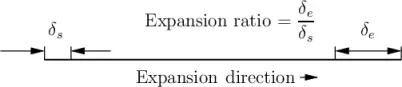
Mesh grading: It is the cell expansion ratios for each direction in the block. It enables the mesh to be graded, or refined, in specified directions. The ratio is that of the width of the end cell `delta_e` along one edge of a block to the width of the start cell `delta_s` along that edge, as shown in Fig.(3).
`fig.(3)`
- Steps 1-3 will be the same as discussed above but we will save the data in a different file.

- We will define the blocks using the same numerical order in hex as in step 4 above but, we will use grading for portions of blocks near walls.
blocks ( hex (3 0 1 2 7 4 5 6) (120 20 1) simpleGrading ( 5 // x-direction expansion ratio ( (0.2 0.3 5) // 20% y-dir, 30% cells, expansion = 5 (0.6 0.4 1) // 60% y-dir, 40% cells, expansion = 1 (0.2 0.3 0.2) // 20% y-dir, 30% cells, expansion = 0.2 (1/5) ) 1 // z-direction expansion ratio ) hex (2 1 9 10 6 5 8 11) (120 20 1) simpleGrading ( 5 // x-direction expansion ratio ( (0.2 0.3 5) // 20% y-dir, 30% cells, expansion = 5 (0.6 0.4 1) // 60% y-dir, 40% cells, expansion = 1 (0.2 0.3 0.2) // 20% y-dir, 30% cells, expansion = 0.2 (1/5) ) 1 // z-direction expansion ratio ) hex (14 2 10 13 15 6 11 12) (80 20 1) simpleGrading ( 0.2 // x-direction expansion ratio ( (0.2 0.3 5) // 20% y-dir, 30% cells, expansion = 5 (0.6 0.4 1) // 60% y-dir, 40% cells, expansion = 1 (0.2 0.3 0.2) // 20% y-dir, 30% cells, expansion = 0.2 (1/5) ) 1 // z-direction expansion ratio ) );For grading along X we simply type 0.2 or 5 as appropriate for finer mesh near the wall.
For grading along Y, replace 1 with the list shown above. In this list, we divide the block along Y into 3 parts containing 20%, 60% & 20% volume for portions near the upper wall, between walls & near the lower wall respectively. This is done by inserting fractional values at the first position in sub-lists. Next, we distribute the number of grid points along with Y (20) between these three parts as 30%,40% & 30% respectively. For this, we insert fractional values at second positions in sub-lists. It is not necessary that grid points along Y be distributed so that the sum of fractions is 1. They can be distributed in any way. - Since we have straight edges we will leave the edges section empty. We will comment out the boundary section and then generate our mesh using blockMesh command as follows,

- On successful creation of mesh (no FOAM FATAL ERRORS) we can use touch command to store our mesh in mesh.foam file,

- We can browse to this file in paraview browser and then click apply to load the .foam file. On selecting "surface with edges" from the toolbar & 2D view we get the desired mesh,

# Setting boundary & initial conditions:
Boundary Conditions:-
The boundary conditions of our mesh is also defined in blockMechDict. In the boundary section, we define all the surface
patches where we want to apply boundary conditions. in our case, the flow enters through the inlet face, experiences no-slip wall boundary condition and then leaves through the outlet face.
So in the boundary section, we first define patch name (depends on user), define a base type to patch and then list the faces on which we want to apply the patch.
For inlet and outlet appropriate base type in "patch". For fixedWalls base type "wall" sets noSlip boundary condition and 2D flow doesn't interact with front & back faces so, appropriate base type for them will be "empty".
boundary
(
	inlet                  //Patch Name = "inlet"
    {
        type patch;        //Base type = "patch"
        faces
        (
            (14 13 12 15)  //List of faces in the patch = "(14 13 12 15)"
        );
    }

	outlet
    {
        type patch;
        faces
        (
			(1 9 8 5)
			(0 1 5 4)
        );
    }

	fixedWalls
    {
        type wall;
        faces
        (
            (15 6 2 14)
            (12 11 10 13)
			(11 8 9 10)
			(7 4 0 3)
			(2 6 7 3)
        );
    }

    frontAndBack
    {
        type empty;
        faces
        (
            (15 6 11 12)
			(6 5 8 11)
			(7 4 5 6)

			(14 2 10 13)
            (2 1 9 10)
            (3 0 1 2)
        );
    }
);
# Initial Conditions :
Transport properties:-
The constant folder contains transport properties that should be defined before simulation. We will set transport model as "Newtonian" & define kinematic viscosity as `1.004" x "10^(-6)" "m^2//s` ,
/*--------------------------------*- C++ -*----------------------------------*
| =========                 |                                                 |
| \      /  F ield         | OpenFOAM: The Open Source CFD Toolbox           |
|  \    /   O peration     | Version:  v2012                                 |
|   \  /    A nd           | Website:  www.openfoam.com                      |
|    \/     M anipulation  |                                                 |
*---------------------------------------------------------------------------*/
FoamFile
{
    version     2.0;
    format      ascii;
    class       dictionary;
    location    "constant";
    object      transportProperties;
}
// * * * * * * * * * * * * * * * * * * * * * * * * * * * * * * * * * * * * * //

transportModel  Newtonian;

nu             [ 0 2 -1 0 0 0 0 ] 1.004E-6;


// ************************************************************************* //
U (velocity vector) :-
Initial conditions of U are located in 0/U. The inflow to domain should be laminar so velocity component along X-direction should be,
`nu_(water) = 1.004" x "10^-6" "m^2//s" at NTP."`
`(R_e)_(water) = 2200" for laminar flow."`
`(U_X)_("initial") = (R_e.nu)/L = ((2200 )(1.004" x "10^(-6)))/0.01 = 0.2209" "m//s^2`
So in inlet patch we will set base type as "fixedValue" and numerical value as "(0.2209 0 0)" .
For fixedWalls base type "noSlip" and velocity will be zero their.
For oultlet, streamwise velocity gradient should be zero (for constant pressure) so, the base type for outlet will zeroGradient.
FrontAndBack patch doesn't interact with fluid in case of 2D flow so we will set its base type as "empty".
The U (velocity vector) file should be modified as shown,
/*--------------------------------*- C++ -*----------------------------------*
| =========                 |                                                 |
| \      /  F ield         | OpenFOAM: The Open Source CFD Toolbox           |
|  \    /   O peration     | Version:  v2012                                 |
|   \  /    A nd           | Website:  www.openfoam.com                      |
|    \/     M anipulation  |                                                 |
*---------------------------------------------------------------------------*/
FoamFile
{
    version     2.0;
    format      ascii;
    class       volVectorField;
    object      U;
}
// * * * * * * * * * * * * * * * * * * * * * * * * * * * * * * * * * * * * * //

dimensions      [0 1 -1 0 0 0 0];

internalField   uniform (0 0 0);

boundaryField
{
    inlet
    {
        type            fixedValue;
        value           uniform (0.2209 0 0);
    }

	outlet
    {
        type            zeroGradient;
    }

	fixedWalls
    {
        type            noSlip;
		value           uniform (0 0 0);
    }

    frontAndBack
    {
        type            empty;
    }
}

// ************************************************************************* //
p (pressure):-
Initial conditions of U are located in 0/U. All the incompressible solvers implemented in OpenFOAM, use the modified pressure, that is,
`p = P/rho" with units "m^2//s^2`
This pressure will be multiplied with density during post-processing to get actual pressure in Pa.
At inlet and outlet patches the pressure gradient remains 0 so, their base type is set as "zeroGradient".
Also at fixedWalls patch pressure gradient is 0 so, the base type will be "zeroGradient".
Again frontAndBack patch doesn't interact with a 2D flow so, its base type will be "empty".
The p (pressure) file should be modified as shown,
/*--------------------------------*- C++ -*----------------------------------*
| =========                 |                                                 |
| \      /  F ield         | OpenFOAM: The Open Source CFD Toolbox           |
|  \    /   O peration     | Version:  v2012                                 |
|   \  /    A nd           | Website:  www.openfoam.com                      |
|    \/     M anipulation  |                                                 |
*---------------------------------------------------------------------------*/
FoamFile
{
    version     2.0;
    format      ascii;
    class       volScalarField;
    object      p;
}
// * * * * * * * * * * * * * * * * * * * * * * * * * * * * * * * * * * * * * //

dimensions      [0 2 -2 0 0 0 0];

internalField   uniform 0;

boundaryField
{
    inlet
    {
        type            zeroGradient;
    }

	outlet
    {
        type            fixedValue;
        value           uniform 0;
    }

    fixedWalls
    {
        type            zeroGradient;
    }

    frontAndBack
    {
        type            empty;
    }
}

// ************************************************************************* //
# Solving & Simulation:
For solving & simulation, we need to open controlDict file located in system/controlDict. This file controls simulation start time, end time, time step size, write interval, etc. In other words, it controls how the simulation runs and the interval at which time directories are stored. Our solver is icoFoam and the simulation runs from 0 to 2 sec. write interval & time step sizes are modified as per the mesh grading.
(setup-1: non-graded mesh) :-
/*--------------------------------*- C++ -*----------------------------------*
| =========                 |                                                 |
| \      /  F ield         | OpenFOAM: The Open Source CFD Toolbox           |
|  \    /   O peration     | Version:  v2012                                 |
|   \  /    A nd           | Website:  www.openfoam.com                      |
|    \/     M anipulation  |                                                 |
*---------------------------------------------------------------------------*/
FoamFile
{
    version     2.0;
    format      ascii;
    class       dictionary;
    location    "system";
    object      controlDict;
}
// * * * * * * * * * * * * * * * * * * * * * * * * * * * * * * * * * * * * * //

application     icoFoam;

startFrom       startTime;

startTime       0;

stopAt          endTime;

endTime         2; //0.5;

deltaT          0.004;

writeControl    timeStep;

writeInterval   5; // This will store time directory every 5th timestep
                      // or every (5x0.004=) 0.02 sec in simulation file

purgeWrite      0;

writeFormat     ascii;

writePrecision  6;

writeCompression off;

timeFormat      general;

timePrecision   6;

runTimeModifiable true;


// ************************************************************************* //
(setup-2: graded mesh) :-
/*--------------------------------*- C++ -*----------------------------------*
| =========                 |                                                 |
| \      /  F ield         | OpenFOAM: The Open Source CFD Toolbox           |
|  \    /   O peration     | Version:  v2012                                 |
|   \  /    A nd           | Website:  www.openfoam.com                      |
|    \/     M anipulation  |                                                 |
*---------------------------------------------------------------------------*/
FoamFile
{
    version     2.0;
    format      ascii;
    class       dictionary;
    location    "system";
    object      controlDict;
}
// * * * * * * * * * * * * * * * * * * * * * * * * * * * * * * * * * * * * * //

application     icoFoam;

startFrom       startTime;

startTime       0;

stopAt          endTime;

endTime         2;

deltaT          0.001;

writeControl    timeStep;

writeInterval   20; // This will store time directory every 20th timestep
                      // or every (20x0.001=) 0.02 sec in simulation file

purgeWrite      0;

writeFormat     ascii;

writePrecision  6;

writeCompression off;

timeFormat      general;

timePrecision   6;

runTimeModifiable true;


// ************************************************************************* //
# Post-processing & Outputs:
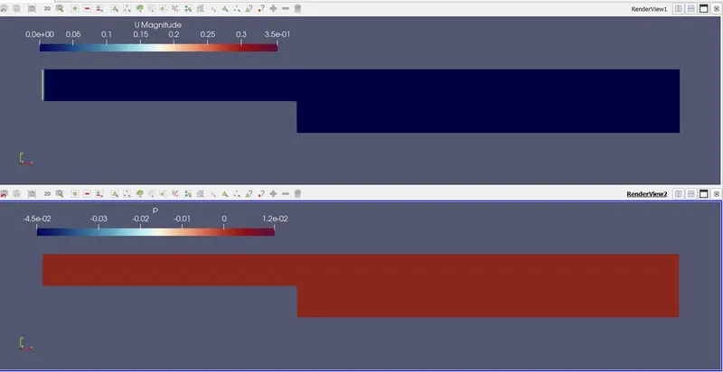
SETUP-1 (non-graded mesh) :-
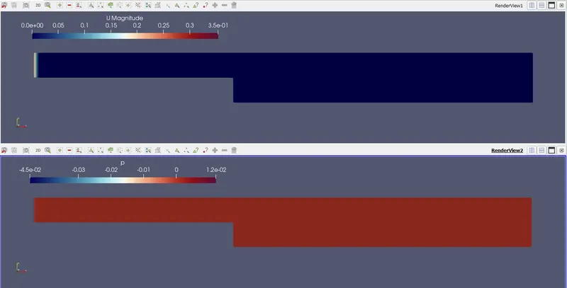
Velocity and pressure distribution at simulation time 0 sec.
SETUP-2 (Graded mesh) :-
Velocity and pressure distribution at simulation time 0 sec.
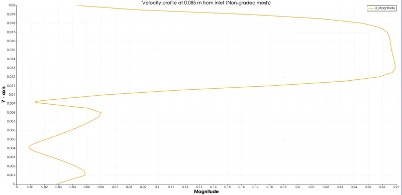
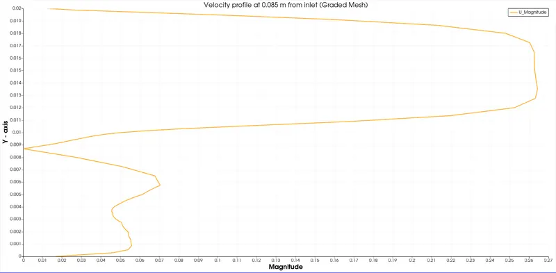
Velocity distribution at 0.085 m from inlet:-
# Obseravations :
- It is seen that the velocity profile near the wall is less jaggy in the case of graded mesh. This is because finer mesh near walls provides more no. of grid points which increase the accuracy of simulation near walls.
- Similar outputs are produced with or without grading the mesh but graded mesh provides much accurate results near walls for the same no. of total grid points.
# Conclusion :
- It is clear by now that grading the mesh is necessary to improve accuracy near critical areas without increasing computational load much.
- Also without grading all the mesh regions will need to be refined leading to unnecessary computation load.