Week 8 - Simulating Cyclone separator with Discrete Phase Modelling
AIM: To perform analysis on cyclone separator and calculate the separation efficiency and pressure drop with discrete phase
modelling.
OBJECTIVE
- To write a few words about any four empirical models used to calculate the cyclone separator efficiency.
- To perform an analysis on a given cyclone separator model by varying the particle diameter from `1mum` to 5`mum` and calculate separation efficiency in each case.Discuss the results.
- To perform an analysis on a given cyclone separator model by varying the particle velocity from 1m/s to 5m/s and calculate the separation efficiency and pressure drop in each case.Discuss the results.
INTRODUCTION
- This work presents a computational fluid dynamics calculation to predict the separation efficiency of cyclone separator and its effect on variation of inlet flow velocity and particle diameter.
- Cyclone separator devices produces a centrifugal forces that is generated by vortex air (higher speed rotating)flow inside the container to separate the particulate from carrier gas, air or liquid.
- The top end is wider than bottom part and air flows in helical pattern from top end to bottom end.
- The more denser particle in the rotating stream have more inertia and strike the wall, then fall to the bottom part and are removed.
- The air is introduced tangentially into the cyclone separator with an inlet velocity Vin, as the carrier gas stream and particle enters into the container, the particle is subjected to drag,centrifugal and boyant forces.
- The bouyant forces also play major role in separating the lower density particle.
- The centrifugal force pushes the particle to the wall(outer flow region) and the drag force pushes the particles to cyclone center(inner flow region).
- When the centrifugal force acting on the particle is greater than drag force,the particles are trapped into the cyclone dust container.
- It is desired for more centrifugal force to act on particle than drag force in an accordance with that the shape of the cyclone separator is considered.
Application
- Large scale cyclones are used in saw mills to remove saw dust from extracted air.
- Used in oil refineries to separate oil and gas.
- These are used in industrial and home kitchen ventillation for separating grease from exhaust air.
- Reduce emission from industrial and manufacturing processes.
Empirical Models
There are some empirical models to find out the separation efficiency.
- Li and Wang model
- This model includes particle re-entrainment and turbulent diffusion at the cyclone wall.It is developed based on following assumptions:
- The radial particle velocity and the radial concentration profile are not constant for uncollected particles within the cyclone.
- The tangential velocity is related to the radius of cyclone by uR^n=constant
2. Koch and Licht Model:
- This model assumes the inherentlyturbulent nature of cyclone and the distribution of gas residence times within the cyclone.
- Koch and Litch describes the particle motion in entrance and collection region with following assumption:
(a) The tangential velocity of the particle is equal to the tangential velocity of the gas flow.(no slip in the tangential direction btween
the particle and the gas).
(b) The tangential velocity is related to the radius of the cyclone by UR^n=constant .
3. Iozia and Leith Model:
- This model assumes that a particle carried by the vortex is enflunced by two forces: (a) Centrifugal force (b) flow resistance
- Developed an improved method to predict cyclone aerodynamic cut diameter(d50) d50:particle size collected with 50% eff.
The efficiency of particle dia (dp) can be calculated from `eta_i=1/(1+((dp_(c))/(d50))^(beta)`
4. Lapple Model :
- It was developed based on Force balance without considering the flow resistance.
- The particles which travel beyond half width of inlet towards the wall are collected with 50% efficiency.
- There is no consideration for type of different shape of inlet.
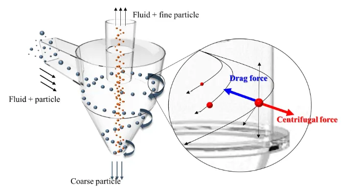
Fig.1 Separation Technique
- Discrete phase modelling: It is used when the aim is to investigate the behaviour of the particles from a lagrangian view.The fluid behaviour in lagrangian view is examined on basis of particle tracking of a particle of fluid flow.
- In DPM, there are two phases namely Continuous phase and Discrete phase .
Discrete phase: smaller particle interacting with continuous phase
continuous phase : fluid flowing within the fluid volume.
SOLVING AND MODELLING APPROACH
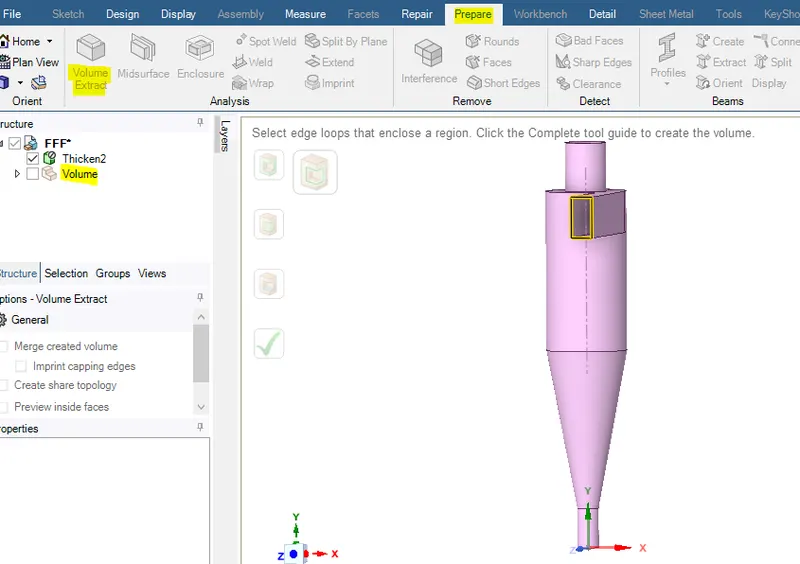
Fig.2 Fuid volume extract
- First of all import the geometry in space claim and then extract the fluid volume.
- Fluid volume is extracted by selecting the inner edges of inlet and outlet section of the geometry.
- Then supress the geometry for physics ans enable only the fluid volume for further analysis.
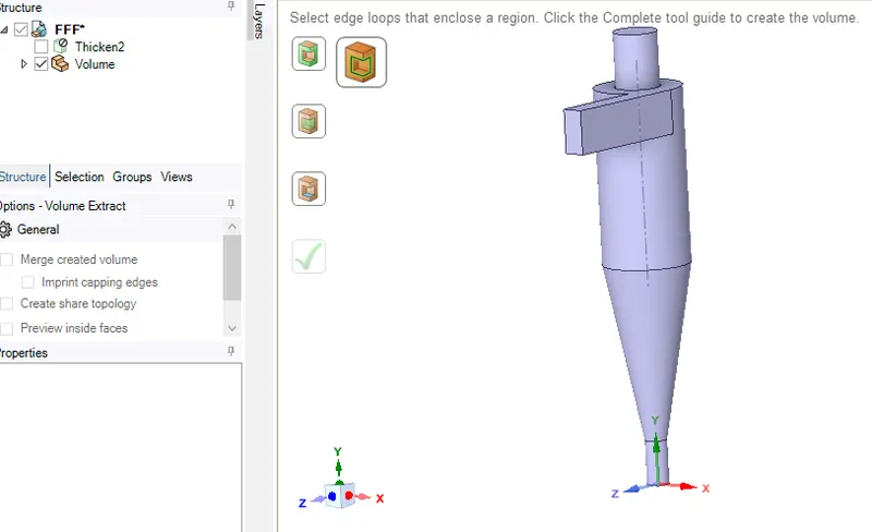
Fig.3 Fluid volume
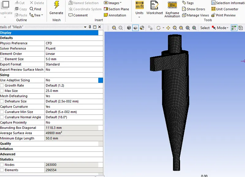
Fig.4 Structured mesh(Hex dominant)
- Hexahedral mesh is used for this geometry, in order to get structured mesh.
PREPROCESSING AND SOLVER SETTING
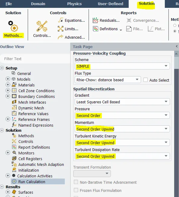
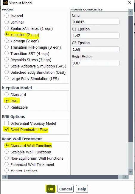
Fig.5 Solution method set up
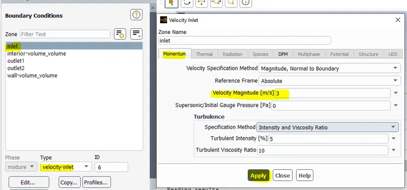
Fig.6 Inlet boundary condition
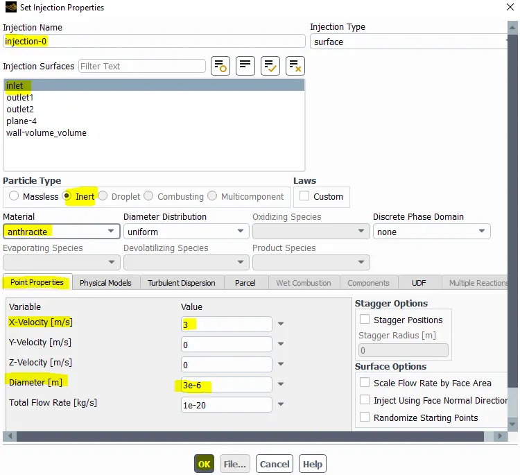
Fig.7 Setting up injection properties
- The injection properties such as particle velocity and diameter is given according to the analysis point of view.The diameter is varied in our case study,so it is being edited in this section.
General setting
Solver type: Pressure Based
Time: Steady
Gravity: -9.81 ( in Y direction)
Viscous model : K-epsilon
K-epsilon: RNG ,swirl dominated flow
Near wall treatment: standard wall finctions
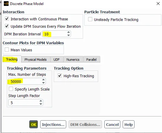
Fig.8 Setting up tracking parameter and DPM iteration
- Enable the interaction with continuous phase: this is coupled flow.
- Then updating the DPM at every 10 iteration interval.
- Here, maximum number of steps is 50000. It is maximum number of time step to track a single particle trajectory, beyond that it will not track that particle.
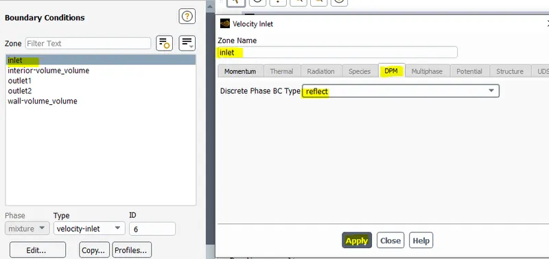
Fig.9 Setting up Discrete phase boundary condition
- Dicrete phase boundary condition: Inlet = reflect
outlet1=escape
outlet2= Trap
RESULTS
CASE 1(a)
Particle diameter = 1`mum`
inlet velocity =3m/s
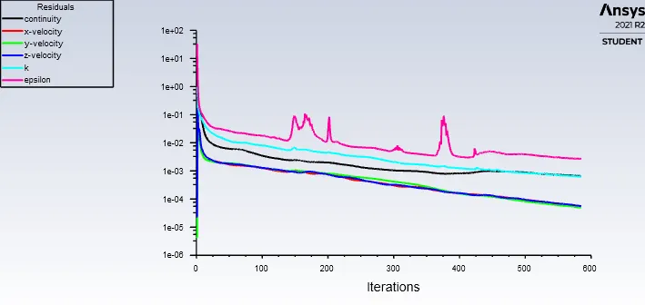
Fig.10 Residual
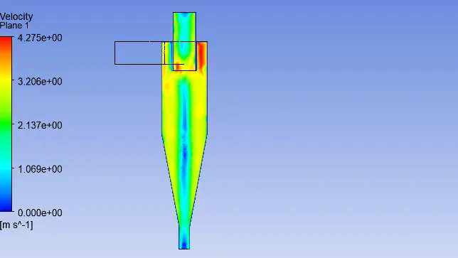
Fig.11 Plane showing velocity magnitude
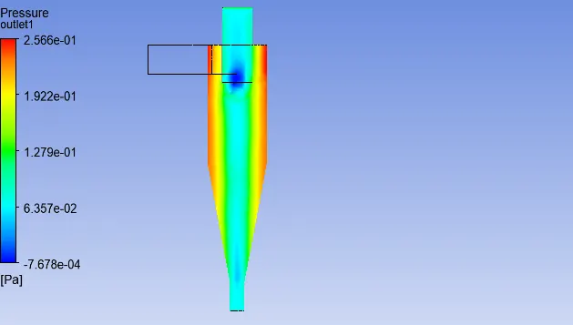
Fig.12 Plane showing pressure magnitude
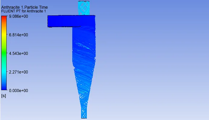
Fig.13 Antracite particle time
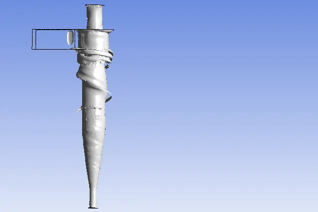
Fig.14 Vortex core
CASE 1(b)
particle diameter= 3`mum`
Flow velocity = 3m/s
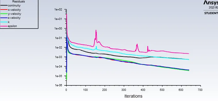
Fig.15 Residual vs iteration
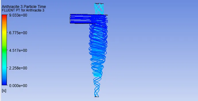
Fig.16 Particle time
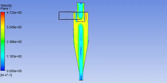
Fig.17 Plane showing velocity magnitude
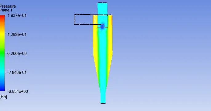
Fig.18 Plane showing pressure magnitude
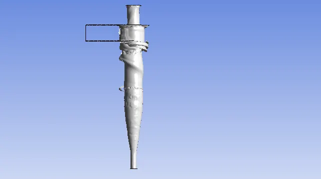
Fig.19 Vortex core
CASE 1(C)
Particle diameter=5`mum`
inlet velocity = 3m/s
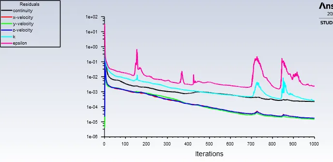
Fig.20 Residual vs iteration
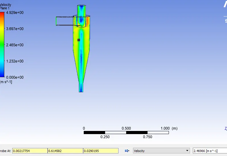
Fig.21 Plane showing velocity magnitude
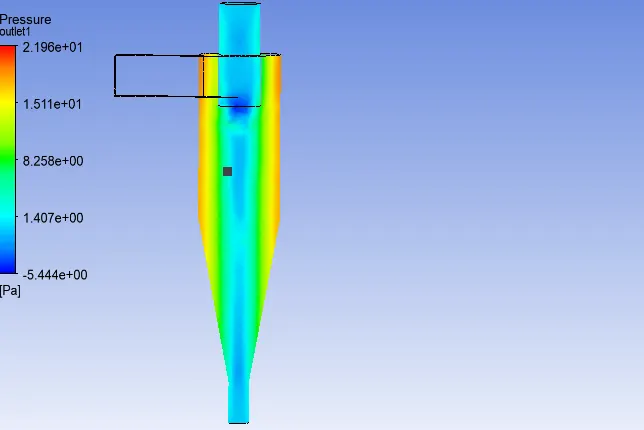
Fig.22 Plane showing pressure magnitude
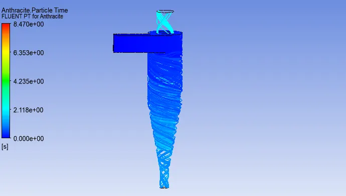
Fig.23 Particle time
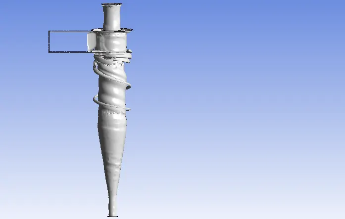
Fig.24 Vortex
CASE 2(a)
Particle diameter: 5`mum`
Flow velocity : 1m/s
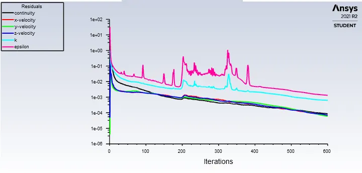
Fig.25
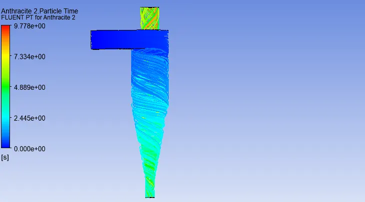
Fig.26 Particle time
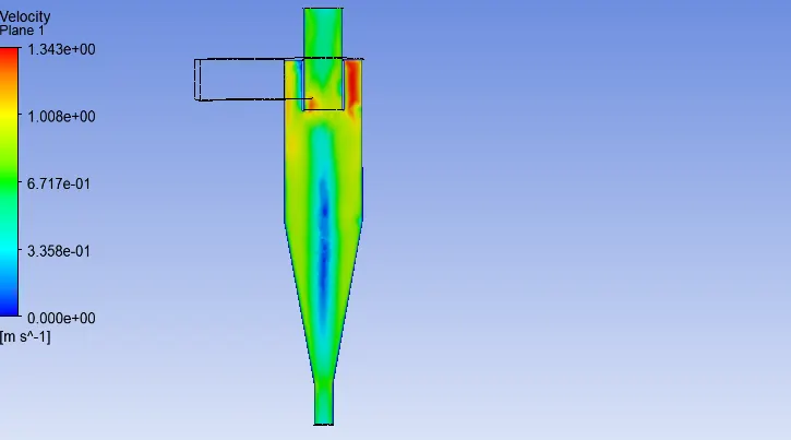
Fig.27 Plane showing velocity magnitude
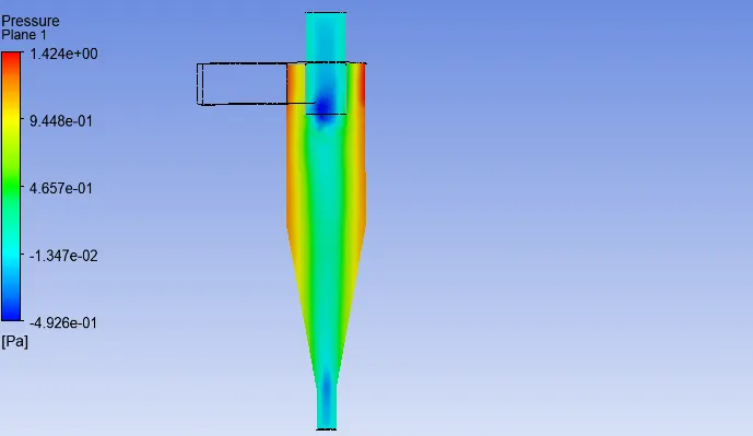
Fig.28 Plane showing pressure magnitude
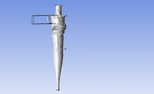
Fig.29 Vortex core
CASE 2(b)
Particle diameter = 5`mum`
Flow velocity = 2m/s
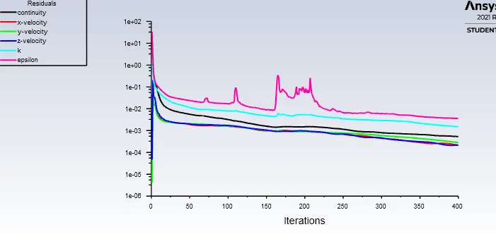
Fig.30 Residual vs iteration
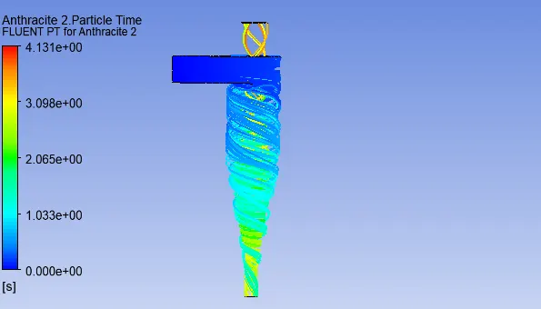
Fig.31 Particle time
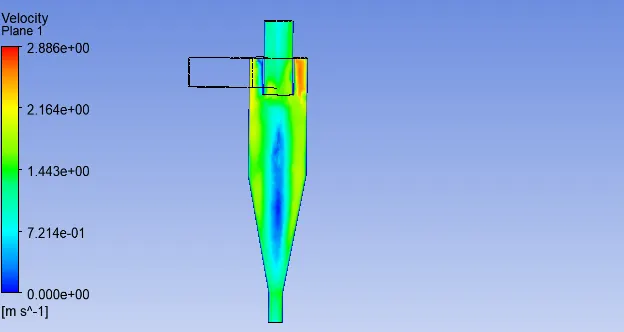
Fig.32 Plane showing velocity magnitude
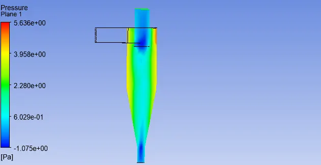
Fig.33 Plane showing pressure magnitude
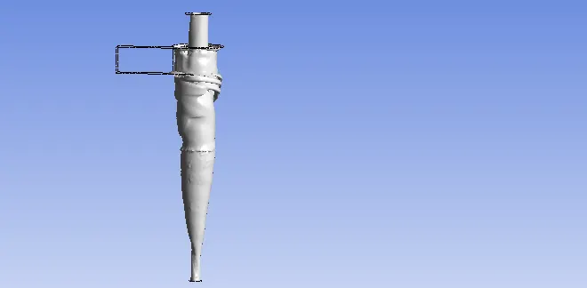
Fig.34 Vortex core
CASE 2(c)
Particle diameter = 5`mum`
Flow velocity = 5m/s
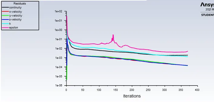
Fig.35 Residual vs iteration
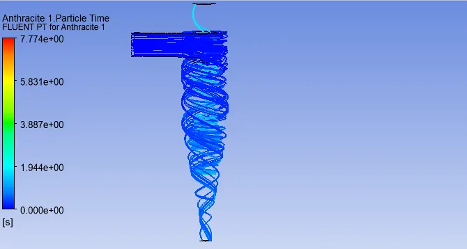
Fig.36 Particle time
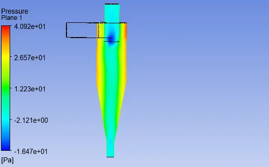
Fig.37 Plane showing pressure magnitude
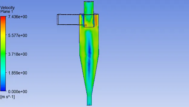
Fig.38 Plane showing velocity magnitude
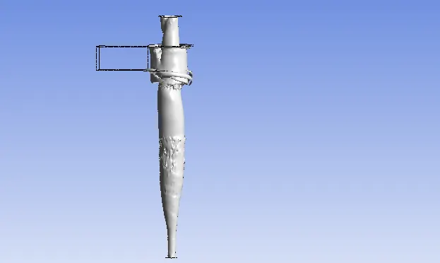
Fig.39 Vortex core
TABLE
| Particle diameter | Flow velocity | separation efficiency | iteration | MFR(kg/s) |
| 1 `mum` | 3m/s | 40% | 600 | 0.0183 |
| 3 `mum` | 3m/s | 45% | 700 | 0.0183 |
| 5 `mum` | 3m/s | 83% | 1000 | 0.0183 |
- Here we increased the particle size from 1`mum` to 5`mum` keeping the inlet velocity of both particle and fluid as 3m/s. The separation efficiency is found to be increased .
- The separation efficiency is maximum for diameter greater than 3`mum`.The maximum is noted as 83% and minimum for particle size 1`mum` as 40%.
- As the particle size decreases ,the role of gravity and inertia does not impact much on eficiency.
- Thus ,the drag force is greater than centrifugal force causing the separation less economy.
| Velocity(m/s) | Particle Diameter | separation efficiency | iteration | Mass flow rate(kg/s) |
| 1 | 5`mum` | 47% | 600 | 0.00612 |
| 2 | 5`mum` | 77% | 400 | 0.0122 |
| 5 | 5`mum` | 81% | 400 | 0.0306 |
- In this case, we are varying the inlet velocity of both particle and fluid stream from 1m/s to 5m/s keeping the particle size constant.
- The eficiency is found to be increase as we are increasing the inlet velocity.
- As the velocity increases , it is creating a suction pull at the middle of the cyclone container( lower pressure).So the inner vortex is effectively collecting the less denser particle and heavier particle is thrown to the wall and collected at the bottom.
| particle dia | Flow velocity(m/s) | Press. inlet(Pa) | Press.outlet(Pa) | pressure Drop(Pa) |
| 5`mum` | 3 | 21.96 | 0.06179 | 21.96-0.06179=21.89 |
| `3mum` | 3 | 18.41 | -0.067 | 18.41+0.067=18.477 |
| 1`mum` | 3 | 17.55 | -0.0439 | 17.55+0.0439=17.593 |
- Here we are finding the pressure drop between inlet and outlet of cyclone separator.It is inferred that by keeping the velocity same for varying the particle size, the pressure drop remains almost same.
- However, the pressure drop is maximum for large particle size followed by smaller particle sie.The maximum pressure drop is being 21.89Pa and minimum is 17.593Pa.
| Flow velocity(m/s) | Particle Diameter | Pressure Inlet(Pa) | Pressure Outlet(Pa) | Pressure Drop.(Pa) |
| 1 | 5`mum` | 1.614 | 0 | 1.614-0=1.614 |
| 2 | 5`mum` | 5.635 | 0.088 | 5.635-0.088=5.547 |
| 5 | 5`mum` | 38.57 | 0.497 | 38.57-0.497=38.07 |
- In this case,we are keping the particle size constant and inlet velocity is varied as shown in table.There is minimum pressure drop for lower velocity and maximum for higher velocity.
- For maximum velocity ,there is maximum pressure pressure drop at core region of cyclone separator.
- separation efficiency = particles trapped / particles tracked
| particle tracked | particle escaped | particle trapped | separation eff. |
particle diameter `mum` |
Flow velocity (m/s) |
| 200 | 60 | 75 | 75/200= 40% | 1 | 3 |
| 200 | 86 | 92 | 92/200= 46% | 3 | 3 |
| 200 | 25 | 166 | 166/200= 83% | 5 | 3 |
| 200 | 107 | 93 | 93/200= 47% | 5 | 1 |
| 200 | 47 | 153 | 153/200= 77% | 5 | 2 |
| 200 | 27 | 151 | 151/200=75% | 5 | 5 |
- The separation efficiency obtained for all case is in betwen 50 % to 80% respectively.The values are taken at some particular iteration
CONCLUSION
- The separation efficiency increase as we are increasing the inlet velocity and particle size respectively.
- Maximum pressure drop is obtained for maximum inlet velocity.
- The centrifugal force dominates over resistance force( drag force) as the velocity increases.
FUTURE STUDY
- To simulate flows with Reynolds stress model.
- Different inlet shape dimension.
REFERENCE
- Park,D.,Sang Go,J.,'Design of cyclone separator critical diameter model based on Machine learning and CFD '.
- Wang,B.,XU,D.L.,'Numerical study of gas-solid flow in a cyclone separator,2006,'Applied mathematical Modelling.
- Gimbun,J.,Chuah,A.,Fakhru I-Razi,A., 'A CFD study on prediction od cyclone collection efficiency',2005,'International journal for Computational methods in engineering science and mechanics.