Week 8 - Simulating Cyclone separator with Discrete Phase Modelling
Aim:- To perform analysis on cyclone separator and calculate the separation efficiency and pressure drop.
Objective:-
- To write a few words about any four empirical models used to calculate the cyclone separator efficiency.
- Part A: To perform an analysis on a given cyclone separator model by varying the particle diameter from 1 μm to 5 μm and calculate the separation efficiency in each case. Discuss the results. [Use both the velocity's as 3m/sec.]
- Part B: To perform an analysis on a given cyclone separator model by varying the particle velocity from 1 m/sec to 5 m/sec and calculate the separation efficiency and pressure drop in each case. Discuss the results. [Use particle diameter size as 5 μm for all cases & keep flow velocity same as particle velocity]
Boundary Conditions:-
- Inlet and wall - Reflect
- Outlet of Top - Escape
- Outlet of bottom - Trap
Theory:-
- Introduction:-
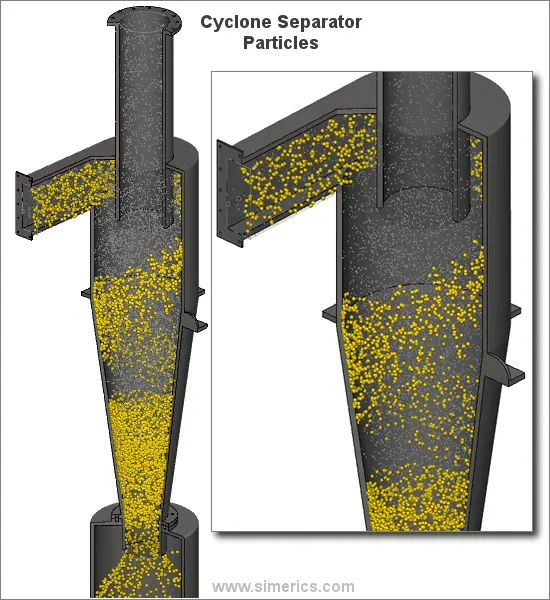
Cyclones are devices that employ a centrifugal force generated by a spinning gas stream to separate particles from the carrier gas. Their simple design, low maintenance costs, and adaptability to a wide range of operating conditions such as sizes and flow rates make cyclones one of the most widely used particle removal devices. By using suitable materials and methods of construction, cyclones may be adapted for use in extreme operating conditions: high temperature, high pressure, and corrosive gases. Cyclones are important particle removal devices in both engineering and process operations.
- Removed components from Cyclone Seperators
1. Dust Particles 2. Partices: Abrasive, Corosive, Adhesive, Explosive.
 v
v 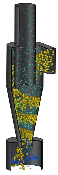
- Working Principle:-
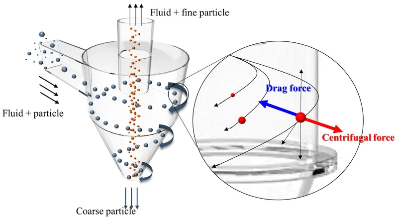
Cyclone separator utilizes cyclone centrifugal force to separate granules from the air. As the above picture, granules containing air firstly enter the inner cyclone separating area of the hopper through inlet. In this area, direction of air is changed from direct entering to down-run with spiral rotating along the screw (as solid line). The high-density dust particles are dragged to hopper lining by centrifugal force. With the air rotating along the screw and the entering of cone part, spiral airflow inside the hopper flows to the center as hopper diameter reduced. In lessened centrifugal force, granules are exhausted along inside hopper to the outlet. However the secondary vortex flow will be formed when airflow reaches the ending part of the cone hopper and will be expelled via upper exhausting pipe of the cone part.
- Pressure Loss
There are varies proportions and styles of the cyclone separator, which generate different pressure losses. Usually, pressure loss of the cyclone separator is about 50~200mmAq.
When cyclone separator is used in positive pressure conveying system, with the large conveying pressure, even there’s much pressure loss of the cyclone separator, it just makes a little influence on the conveying effect. We generally attach more attention to the separation effect.
In negative pressure conveying system, the air-source equipment usually has low suction pressure, the less pressure loss of cyclone separator, the better. In designing of the cyclone separator, it should estimate its pressure loss precisely, and calculate the output pressure of the air-source equipment.
- Separation Effectiveness
Ordinarily, the cyclone separator is applicable to separate the non-viscous, non fiber dry dust greater than 1-3 micrometers. By accurate calculation and appropriate technological structure, it can get supreme separation effect eventually. For large size granules, the separating rate can reach above 97%. The granule in smaller size or is more light, the more difficult to separate effectively.
Cyclone separators are generally able to remove somewhere between 50-99% of all particulate matter in flue gas. How well the cyclone separators are actually able to remove this matter depends largely on particle size. If there is a large amount of lighter particulate matter, less of these par0ticles are able to be separated out. Because of this, cyclone separators work best on flue gases that contain large amounts of big particulate matter.
- Variants
1. High throughput Cyclones have Diameter >1.5 m and suitable for seperating particles 20m or larger.
2. High efficiency Cyclones have a diamter 0.4 to 1.5m and It can be used to sperated particles 10m or larger.
3. Cyclones with diameter between 0.005 to 0.3 m are no longer used Independently but are constructed into Multi- cyclones. In this case Inflow of gas doesn't take place tangentially but axially, after which gas is made to spiral via splitter blades. A multi-cyclone require's gas to be well distributed across the smaller cyclones. If there is insufficient distribution, this may lead to gas back-flow and blockages.
-
Advantages and Disadvantages
There are many advantages associated with cyclone separators, some of these include:
- Cheap to purchase.
- Low maintenance.
- Suitable for high temperatures.
- Suitable for liquid mists.
- Do not require much space.
Some disadvantages are associated with cyclone separators, but these disadvantages can be reduced in severity if the correct separator is selected for the correct application. Disadvantages may include:
- Increased operating costs associated with the pressure drop (assuming large pressure drop).
- Inefficient when handling small/fine particles.
- Not suitable for ‘sticky’ substances.
An inaccuracy in cyclone efficiency prediction may result in an inefficient design of cyclone separators. Models to predict the behaviour of cyclones are usually empirical.
1.1 IOZIA AND LEITH MODEL
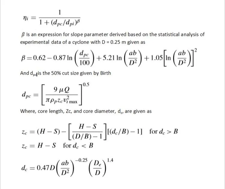
Iozia and Leith (1990) logistic model is a modified version of Barth (1956) model which is developed based on force balance. The model assumes that a particle carried by the vortex endures the influence of two forces: a centrifugal force, Z, and a flow resistance, W. The addition made by Iozia and Leith on the original Barth (1956) model are the core length zc and slope parameter β
expression which is derived based on the statistical analysis of experimental data of cyclone with D = 0.25 m. The collection efficiency ηi of particle diameter dpi can be calculated from
1.2 LI AND WANG MODEL
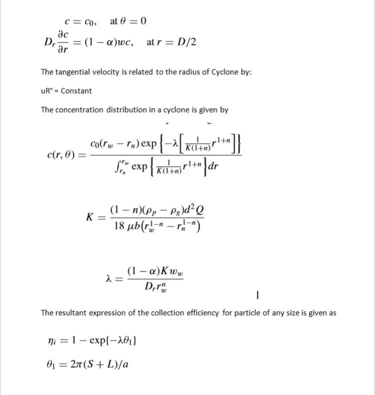
The Li and Wang (1989) model includes particle bounce or re-entrainment and turbulent diffusion at the cyclone wall. A two-dimensional analytical expression of particle distribution in the cyclone is obtained. Li and Wang model was developed based on the following assumptions:
• The radial particle velocity and the radial concentration profile are not constant, for uncollected particles within the
cyclones.
• Boundary conditions with the consideration of turbulent diffusion coefficient and particle bounce re-entrainment on
the cyclone wall are:
1.3 KOCHI AND LICHT MODEL
Koch and Licht (1977) collection theory recognized the inherently turbulent nature of cyclones and the distribution of gas residence times within the cyclone. Koch and Licht describe particle motion in the entry and collection regions with the additional following assumptions:
• The tangential velocity of a particle is equal to the tangential velocity of the gas flow, i.e. there is no slip in the tangential
direction between the particle and the gas.
• The tangential velocity is related to the radius of cyclone by: uRn = constant. A force balance and an equation on the particles collection yields the grade efficiency ηi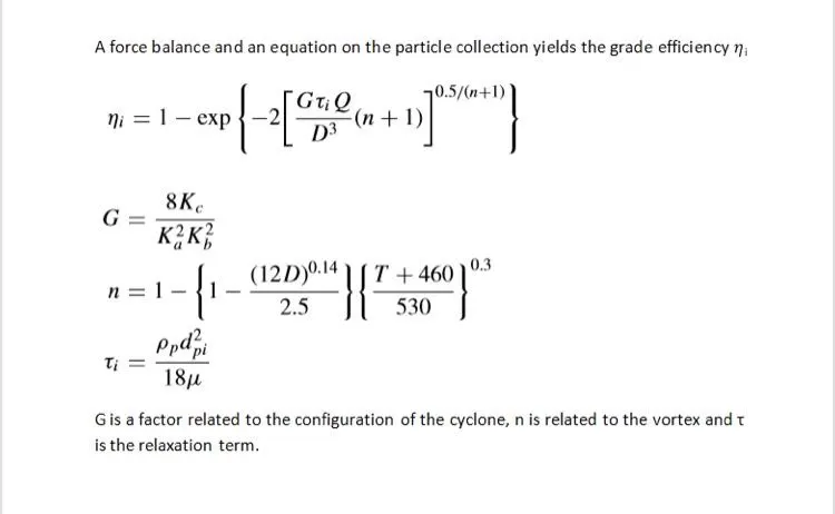
1.4 LAPPLE MODEL
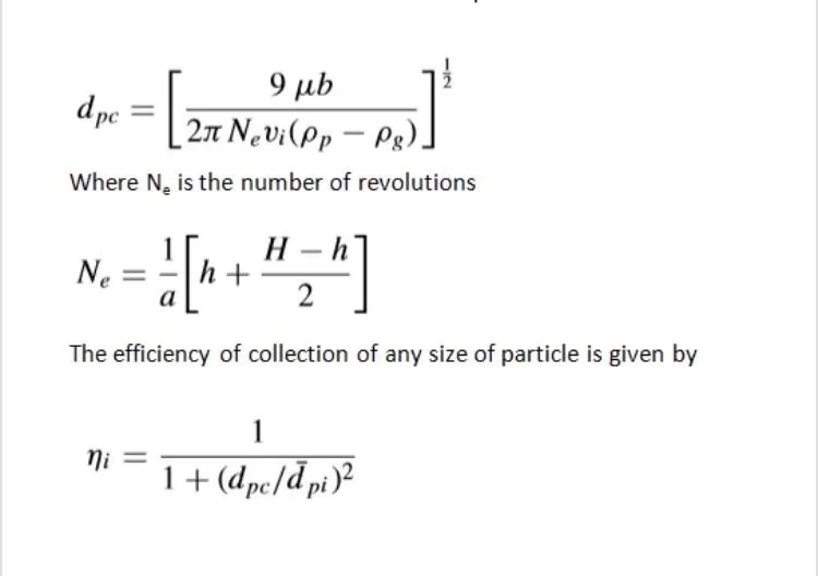
Lapple (1951) model was developed based on force balance without considering the flow resistance. Lapple assumed that a particle entering the cyclone is evenly distributed across the inlet opening. The particle that travels from inlet half width to the wall in the cyclone is collected with 50% efficiency. The semi empirical relationship developed by Lapple (1951) to calculate a 50% cut diameter, dpc, is
Applications:-
- Chemical and Petrochemical Processes.
- Industrial, Metallurgical and Power Generation.
- Food and Pharmaceutical.
- Cement Industries.
----------------------------------------------------------------------------------------------------------------------------------------------
Modelling Approach:-
For this analysis we use the Cyclone Separator which provide a method of removing particular matter from air or other gas streams at low cost and low maintenance. For this case we use the Discrete phase Modelling (DPM) Setup in the Ansys Fluent for the simulation.
There are 2 phases as given Below:
- Continuous Phase: It consists of Fluid flowing within the Fluid Volume.
- Discrete Phase: It consists of smaller particles interacting with continous Phase and It also exchange momentum, mass and energy with fluid phase or continous phase.
In the Discrete Phase Modelling (DPM) we have two ways to carried out DPM
- Uncoupled-flow: In this type of flow, Discrete Phase will not interact with the continous Phase.
- Coupled-flow: It will influence the flow of continous phase.
For, this analysis we have used the coupled-flow in DPM to get accurate results.
The collection efficiency of cyclones varies as a function of density, particle size and cyclone design. Cyclone efficiency will generally increase with increases in particle size and/or density; inlet duct velocity; cyclone body length; number of gas revolutions in the cyclone; ratio of cyclone body diameter to gas exit diameter; inlet dust loading; smoothness of the cyclone inner wall. To check the effect on the Separation efficiency we will perform an analysis on given Cyclone model in two different manners.
- By varrying Particle diameter: from 1 μm to 5 μm.
- By varrying Particle Velocities: from 1m/s to 5m/s.
For Part A we will the cases, of varrying Particle diameter:
- A1
- A2
- A3
- A4
- A5
For Part B we will the cases, of varrying Particle Velocities:
- B1
- B2
- B3
- B4
- B5
----------------------------------------------------------------------------------------------------------------------------------------------
Solving Approach:-
Geometry:
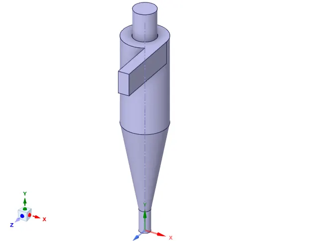
- Import the Geometry in Fluent spaceclaim, named as Cyclone Separator.stp
- Then Extract the Fluid Volume by selecting the inner edges at Inlet and Outlet's of the geometry.
- After that Hide the Geometry and Supress it for Physics.
- save the Fluid Volume for further Processes.
Meshing:-
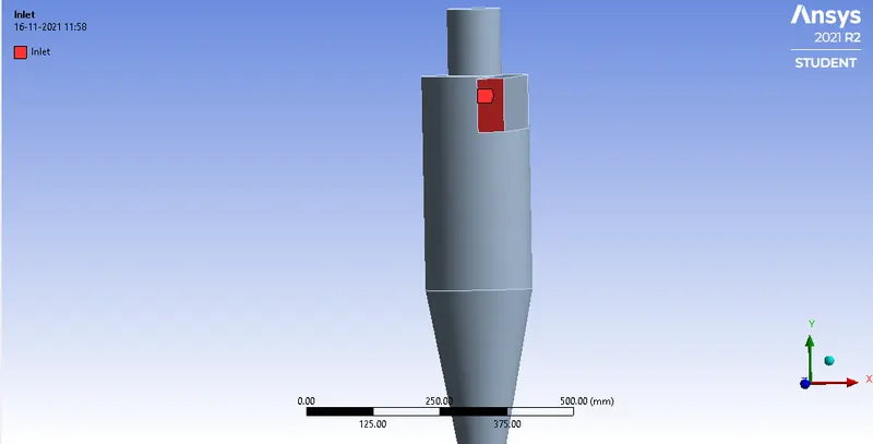
- First, we have given the names for the boundary conditions by the named - selection command as given below:-
Inlet
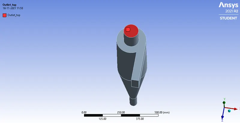
Outlet_top
Outlet_bottom
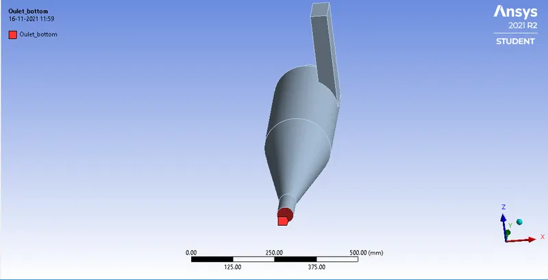
- here, we are 1 inlet and 2 Oultet's as Outlet_top and Outlet_bottom.
- Outlet_top for Lighter gas and Outlet_bottom is used for Collecting heavy particles, which drops due to gravity at the bottom.
Generate Mesh
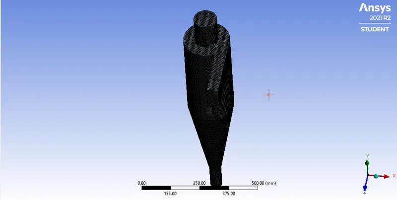
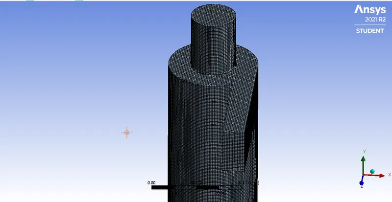
- Here, the Geometry of Cyclone separator is simple and we are using Structrual Mesh because It gives the best results.
- The element size is 5 mm and no. of elements = 427841.
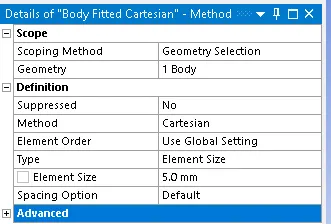

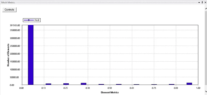
- Mesh quality
Setup:-
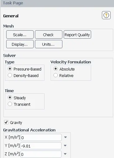
- Solver => Pressure based, Time =>Steady state.
- Gravity is in negatve y direction -9.81 m^2/s.
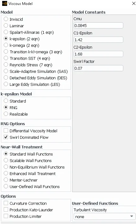
- Viscous Model => K-epsilon
- K-epsilon => RNG, RNG option: Swirl dominated Flow. This enhances the accuracy of the swirling flows.
- Near wall treatment : Standard wall
- DPM settings:-
Here, we will see the Settings for both the cases as given below:
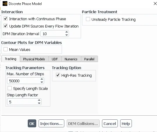
- we have to enable the 'Interaction with continuous phase' This will enable the Coupled-flow.
- And we have to enable the 'Update DPM Sources Every Flow Iterations' by enabling this Option, gives the chance to calculate the Particle Source Terms at every Iteration.
- Set DPM Iteration Interval = 10 (It is default value) and This option allows us to control the frequency at which Particles attracts.
- Here, In the Tracking paramters 'Maximum number of time steps is 50000' It is given by default for the steady state It helps to compute a single trajectory of particle.
- 'Step length factor = 5' This is used to control the size of time step larger the Factor, smaller the time step will be.
- Here, we have not used 'Specify length scale factor' because It is used for controlling the Time step size, by dividing Length scale with Velocity of Discrete Particle and Velocity with Velocity of continous Phase.
Here, are the Settings For Both Cases Part A and Part B:-
| Divisions | Cases | X velocity (m/s) | Diamter of Particle(μm) |
| Part A | A1 | 3 | 1e-6 |
| A2 | 3 | 2e-6 | |
| A3 | 3 | 3e-6 | |
| A4 | 3 | 4e-6 | |
| A5 | 3 | 5e-6 | |
| Part B | B1 | 1 | 5e-6 |
| B2 | 2 | 5e-6 | |
| B3 | 3 | 5e-6 | |
| B4 | 4 | 5e-6 | |
| B5 | 5 | 5e-6 |
- As, per the above table We have to compute 10 cases by varrying the Diameter of Particle and by varrying of the x- velocity.
- In the Cases of Part A we compute the simulation by the fixing the x- velocity and by varring th particle diameter as 1 μm to 5 μm.
- In the Cases of Part B we compute the simulation by the fixing Diameter of particle and varrying the x - velocity as 1 m/s to 5 m/s.
Particle Injection:-
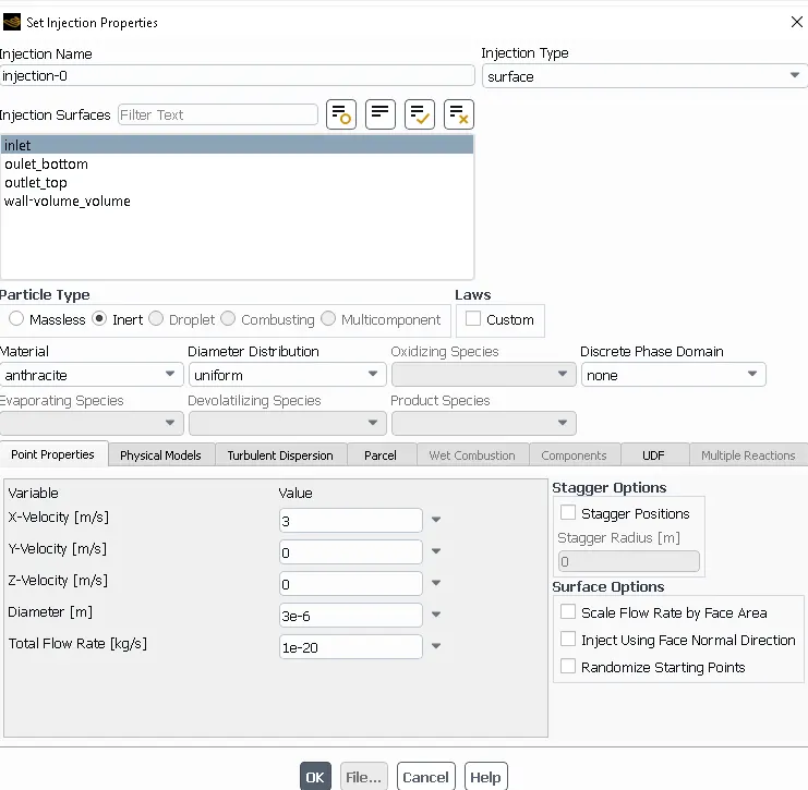
- We have to click on Injections and then Go to create Injection For injection of particles in Cyclone seperator.
- Injection Type => Surface
- Release From Surface => Inlet
- Particle Type => Inert
- Material => Anthracite
- Total Flow rate => 1e-20.
- Boundary conditions:-
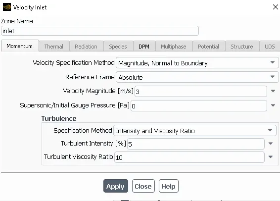
- The magnitude of Velocity is shown in the above Figure is for only one case We have to varry the magnitude of velocity for the B part with the varriation in the values of x- velocity. simply, we have to varry the 'x-velocity' for the Part B and also we have to varry the Velocity in the Boundary conditions as well.
- DPM boundary conditions Setup:-
- Inlet => Type: Velocity-inlet
- DPM: Reflect.
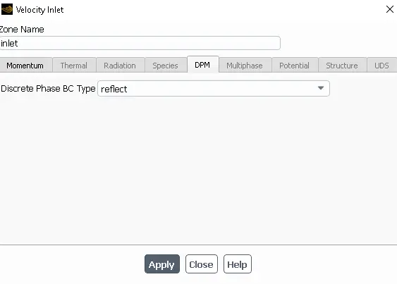
- Oulet_top => type: Pressure-Outlet.
- Gauge Pressure: 0 Pa.
- DPM: Escape.
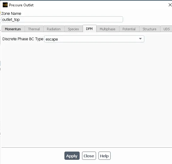
- Oulet_bottom => type: Pressure-Outlet.
- Gauge Pressure: 0 Pa.
- DPM: Trap.
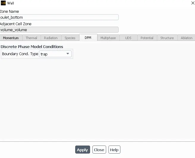
- Wall => Type: Wall.
- Wall Motion=> Stationary wall, No Slip condition.
- DPM : Reflect.
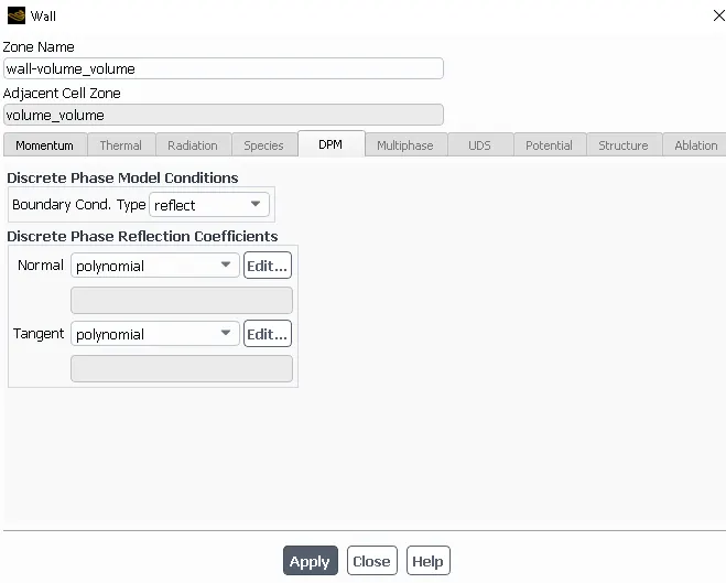
Here, In the Boundary conditions we have given the different PDM conditions like Reflect, Escape and Trap.
- Reflect: It is a Particle Rebound off the boundary in question with a change in its momentum as defined by the Coffecient of restitution.
- Escape: The particle is reported as having 'escaped' when It encounters the boundary in question. Trajectories calculated are terminated.
- Trap: The trajectory calculated is terminated and the Fate of the Particle is recorded as 'Trapped'. In the case of evaporating droplet, their entire mass instantaneously passes into the vapor phase and enters the Cell adjacent to the boundary. In the case of combusting particle, the remaining volatile mass is passed into the vapor phase.
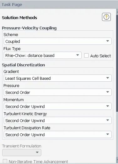
- Solution Method:- Scheme: Coupled
- Apart From the default settings we have to changed some of the Settings as shown in the given Image below.
- Momentum, Turbulent Kinetic Energy and Turbulent Dissipation Rate set to be Second Order Upwind scheme for more accurate Results.
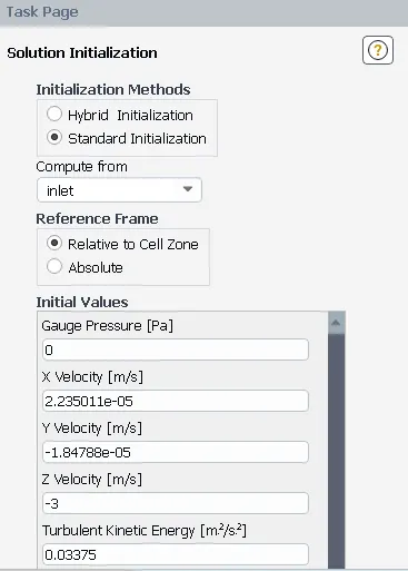
- Initialization => Standard Initialization because we have both Inlet and Oultet hence, It is more suitable for this case.
- We have to set Compute From 'Inlets' Then Initialise the every case.
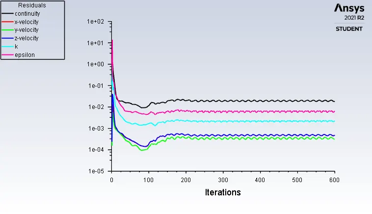
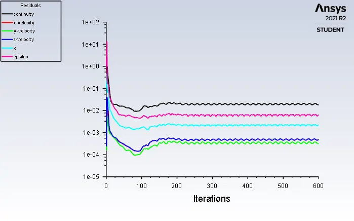
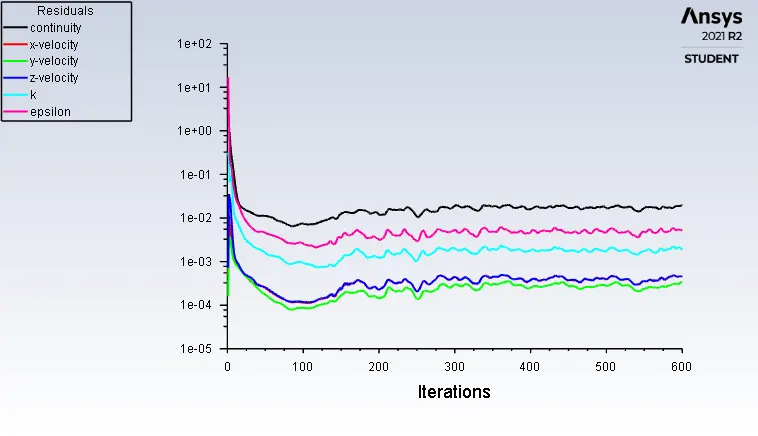
- Run and Calculation: The number of Iterations we have given For each Case is '600' and Then run the Case.
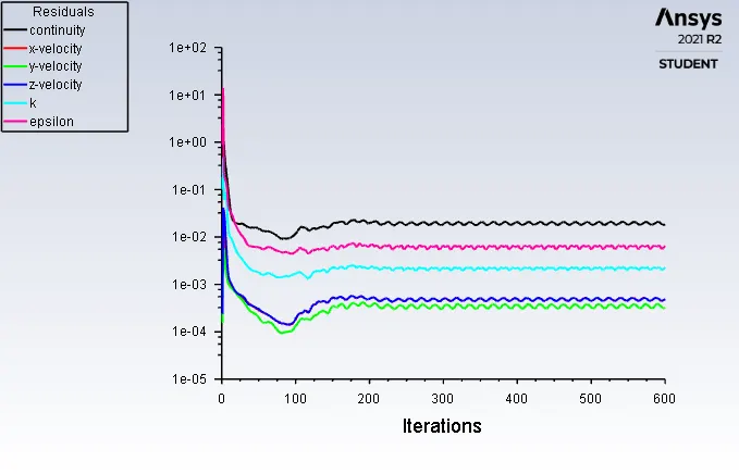
- After run upto '600' Iterations we got these results shown below:
-----------------------------------------------------------------------------------------------------------------------------------------------
Results:- For both Part A and Part B respectively.
Here, we have to compute the Separation Efficiency and Pressure Drop for all cases.
Separation Efficiency:-
It is basically the fraction of particles of a given size collected in the Cyclone compared to those of that size going into the cyclone. For this case Separation Efficiency is defined as the ratio of concentration that has been removed from the feed stream to the initial concentration in the feed stream. or basically you can say that the number of trapped particles to the total number of particles tracked.
Separation Efficiency = (No. of Particles Trapped)/ (No. of Particles Tracked).
Experience shows that collection efficiency of cyclone separator increases with increasing particle mean diameter and density; increasing gas tangential velocity; decreasing cyclone diameter; increasing cyclone length; extraction of gas along with solids through the cyclone legs.
Pressure Drop:-
Pressure drop across the cyclone is of much importance in a cyclone separator. The pressure drop significantly affects the performance parameters of a cyclone. The total pressure drop in a cyclone will be due to the entry and exit losses, and friction and kinetic energy losses in the cyclone. Normally most significant pressure drop occurs in the body due to swirl and energy dissipation.
Or we can calculate the Pressure Drop as Total Inlet Pressure - Total Outlet Pressure
As the 'Escape' DPM condition is given to the Outlet_top in this case, so Outlet top is considered in Pressure drop for the Calculation.
The efficiency of a cyclone collector is related to the pressure drop across the collector. This is an indirect measure of the energy required to move the gas through the system. The pressure drop is a function of the inlet velocity and cyclone diameter.
Results:- For Part A and Part B
Case: A1
Residuals:-
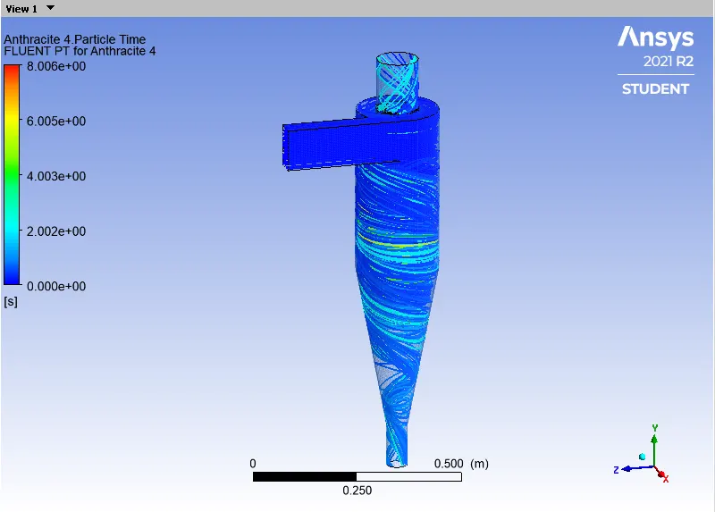
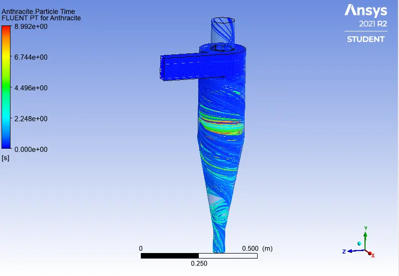
Particle Resident Time:-
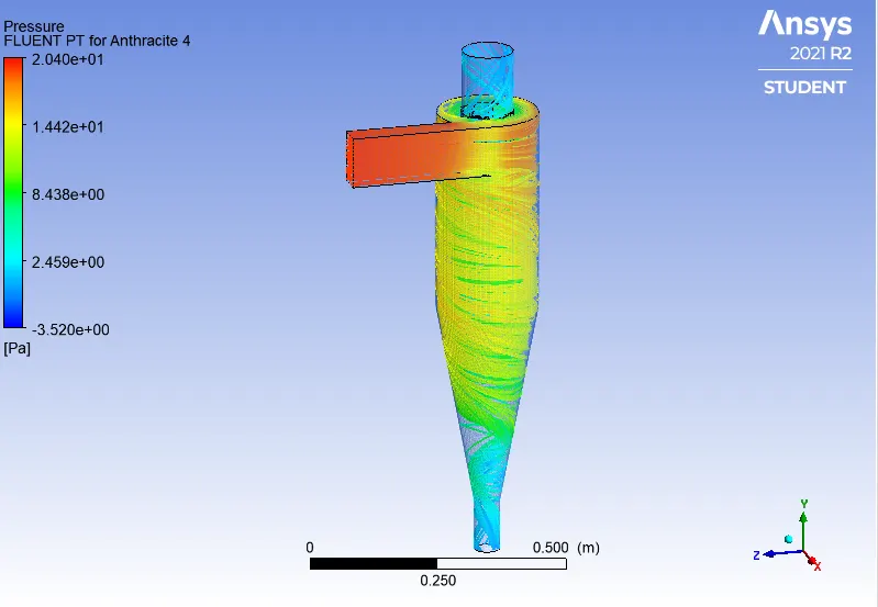
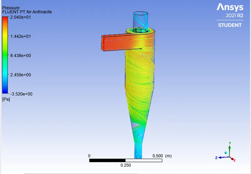
Pressure:-
Separation Efficiency = (No. of Particles Trapped)/ (No. of Particles Tracked)
Separation Efficiency = (259/378)*100
Separation Efficiency = 68.51%
Case: A2
Residuals:-
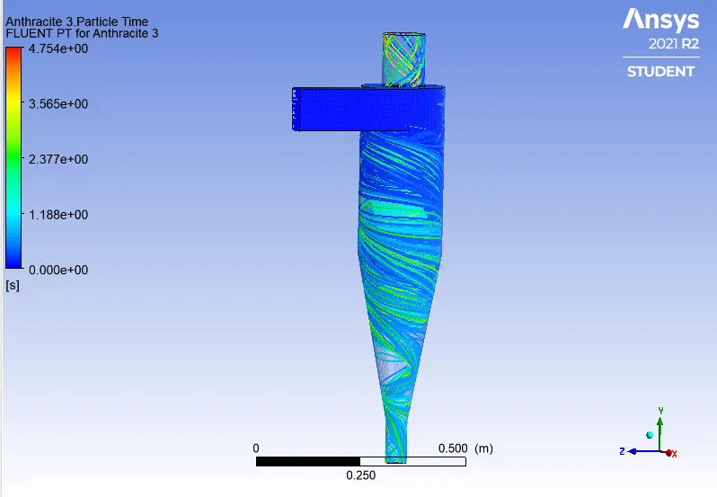
Particle Resident Time:-
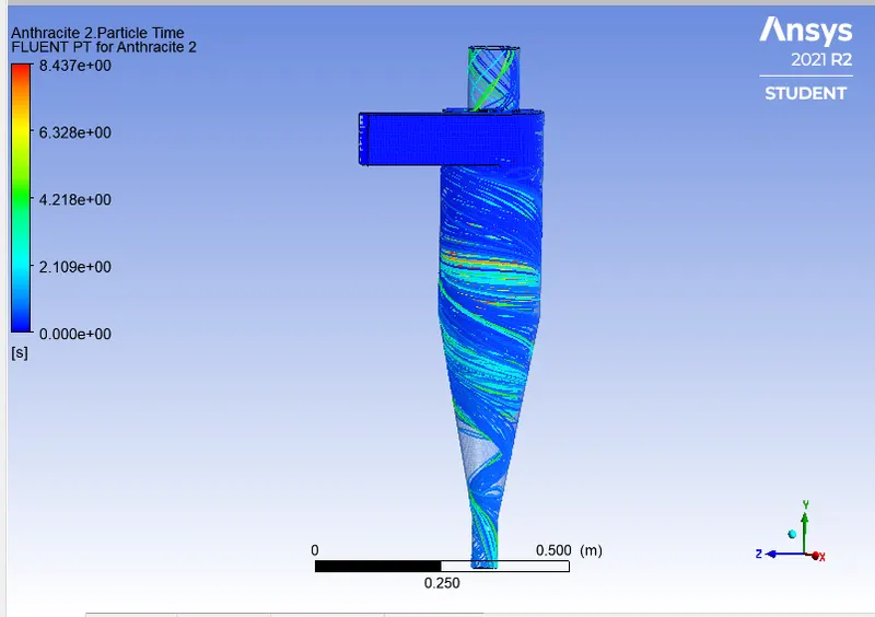
Pressure:-

Separation Efficiency = (No. of Particles Trapped)/ (No. of Particles Tracked)
Separation Efficiency = (274/378)*100
Separation Efficiency = 72.24%
Case: A3
Residuals:-
Particle Resident Time:-
Pressure:-
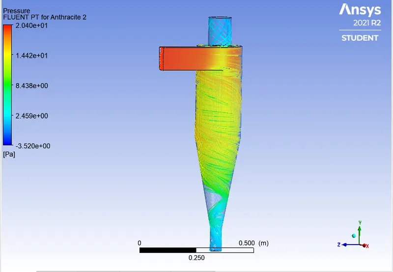
Separation Efficiency = (No. of Particles Trapped)/ (No. of Particles Tracked)
Separation Efficiency = (299/378)*100
Separation Efficiency = 79.10%
Case: A4
Residuals:-
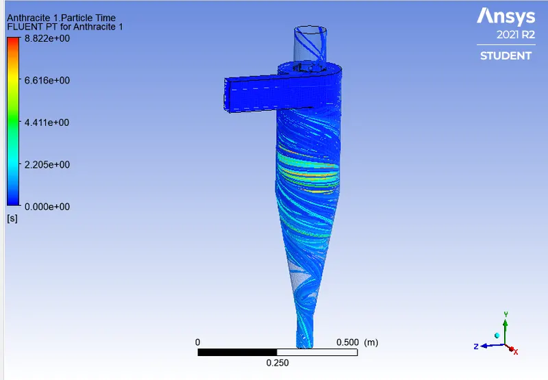
Particle Resident Time:-
Pressure:-
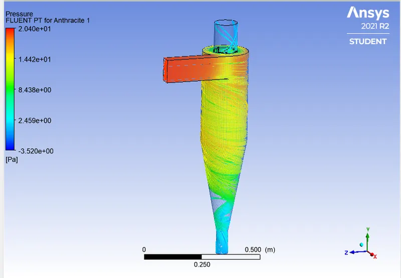
Separation Efficiency = (No. of Particles Trapped)/ (No. of Particles Tracked)
Separation Efficiency = (321/378)*100
Separation Efficiency = 84.92%
Case: A5
Residuals:-
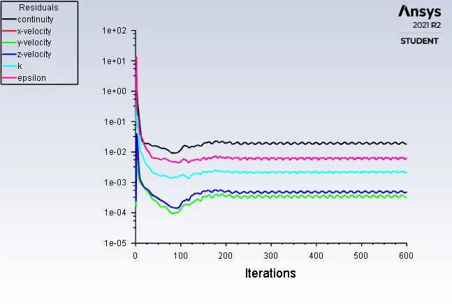
Separation Efficiency = (No. of Particles Trapped)/ (No. of Particles Tracked)
Separation Efficiency = (352/378)*100
Separation Efficiency = 93.92%
Pressure Drop for these case's should be Same Because there is no change in the Velocity So, the Pressure drop also remains same and the Pressure Drop is
Pressure drop = Pressure at Inlet - Pressure at Oulet
Pressure Drop = 1.8489 - 0.01473
Pressure Drop =1.7016 pa
Results for Part B
Case: B1
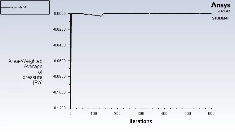
Residuals:-
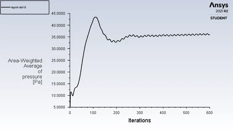
Pressure at Inlet:-
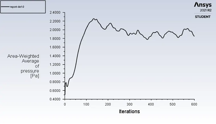
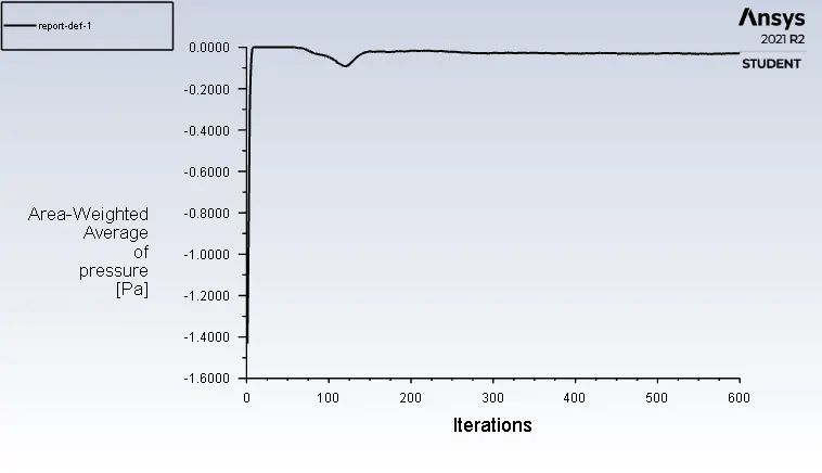
Pressure at Outlet-top:-
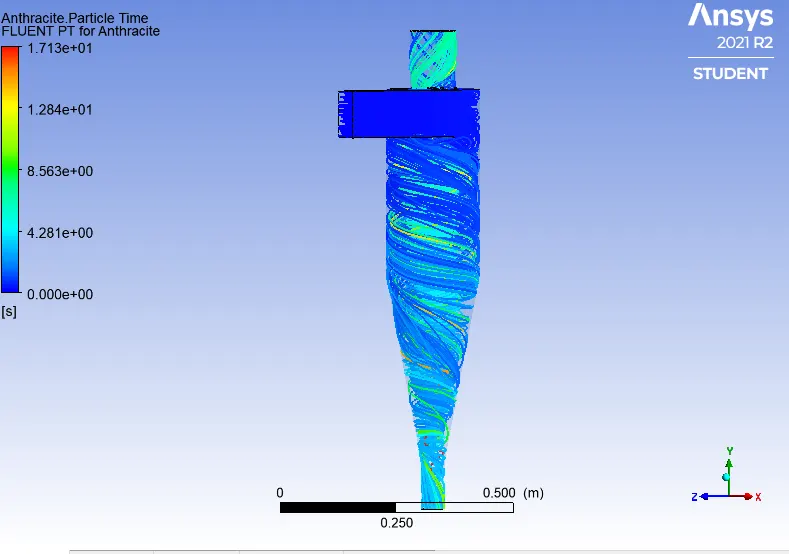
Particle Resident Time:-
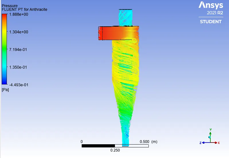
Pressure:-
Separation Efficiency = (No. of Particles Trapped)/ (No. of Particles Tracked)
Separation Efficiency = (189/378)*100
Separation Efficiency = 50%
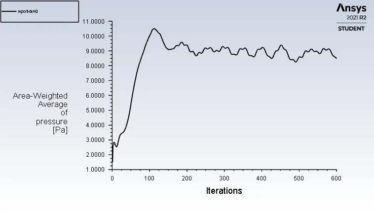
Pressure drop = Pressure at Inlet - Pressure at Oulet
Pressure Drop = 1.8489 - 0.00063
Pressure Drop =1.8482 pa
Case: B2
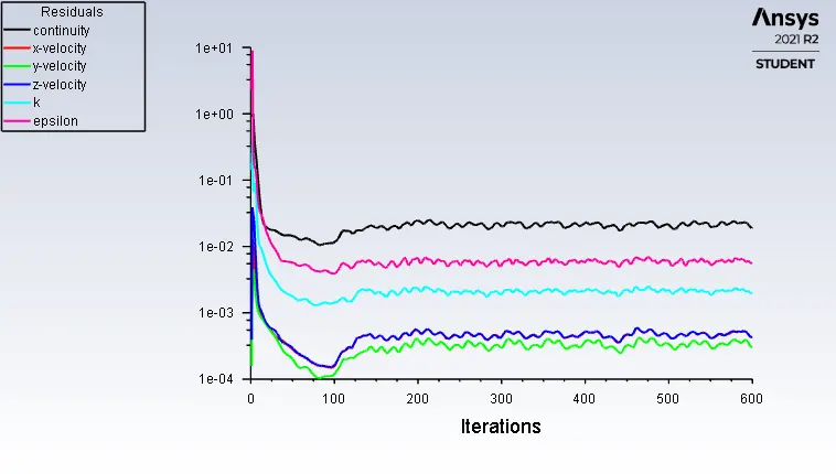
Residuals:-
Pressure at Inlet:-
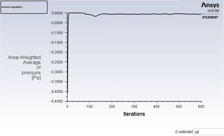
Pressure at Outlet-top:-
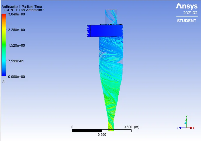
Particle Resident Time:-
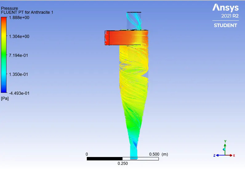
Pressure:-
Separation Efficiency = (No. of Particles Trapped)/ (No. of Particles Tracked)
Separation Efficiency = (323/378)*100
Separation Efficiency = 85.94%
Pressure drop = Pressure at Inlet - Pressure at Oulet
Pressure Drop = 1.8489 - 0.00588
Pressure Drop =1.8431 pa
Case: B3
Residuals:-
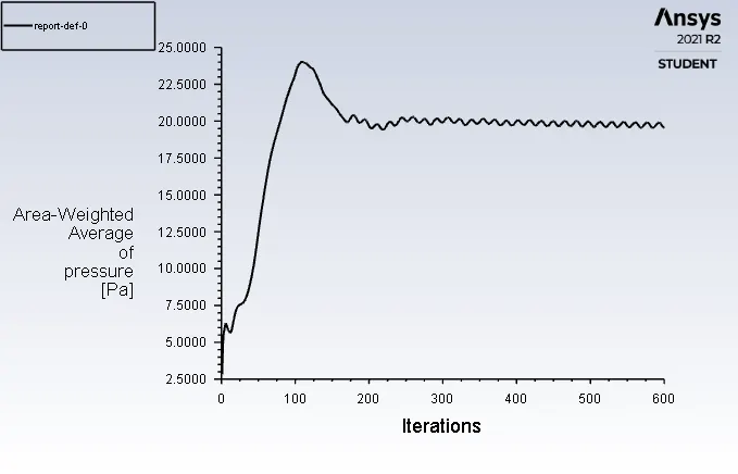
Pressure at Inlet:-
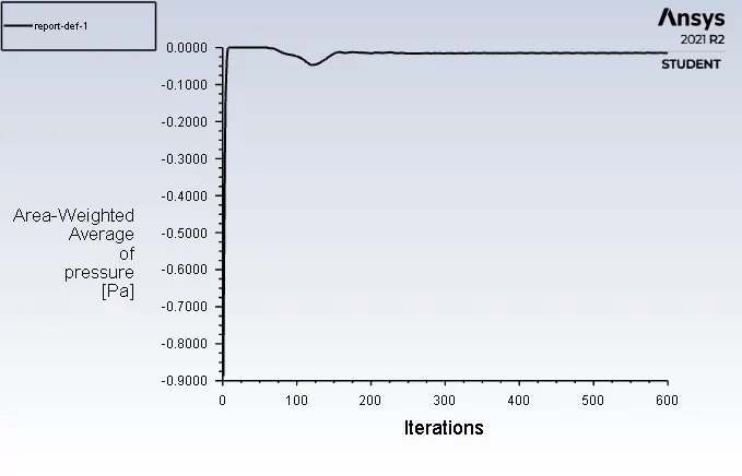
Pressure at Outlet-top
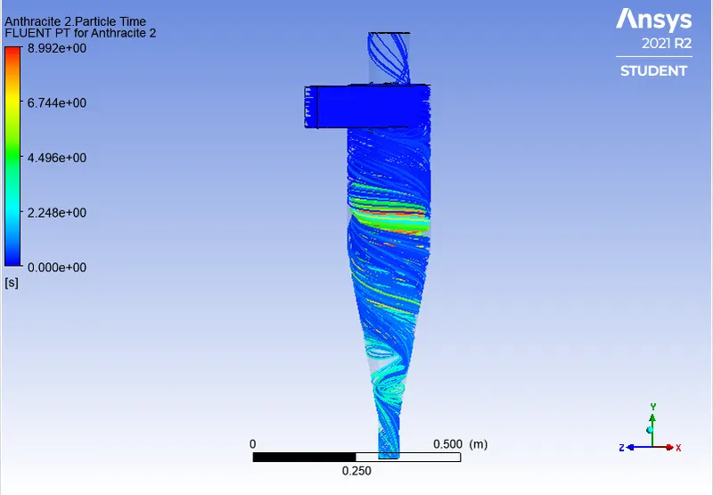
Particle Resident time:-
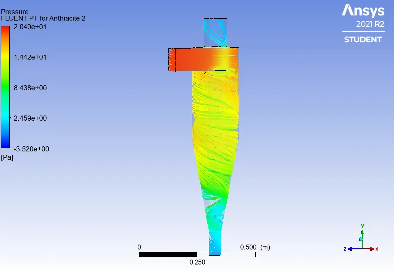
Pressure:-
Separation Efficiency = (No. of Particles Trapped)/ (No. of Particles Tracked)
Separation Efficiency = (330/378)*100
Separation Efficiency = 87.30%
Pressure drop = Pressure at Inlet - Pressure at Oulet
Pressure Drop = 1.8489 - 0.01473
Pressure Drop =1.7016 pa
Case: B4
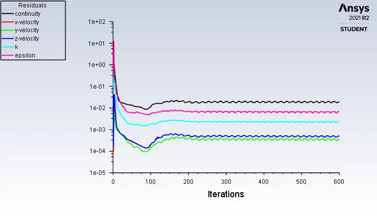
Residuals:-
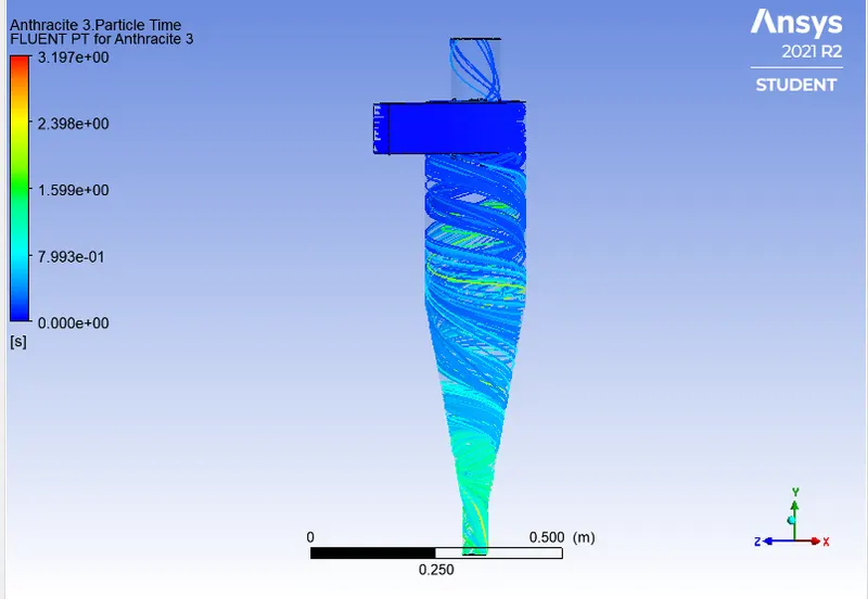
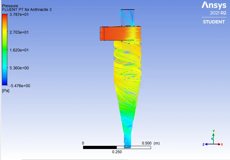
Separation Efficiency = (No. of Particles Trapped)/ (No. of Particles Tracked)
Separation Efficiency = (334/378)*100
Separation Efficiency = 88.35%
Pressure drop = Pressure at Inlet - Pressure at Oulet
Pressure Drop = 1.8489 - 0.029035
Pressure Drop =1.8198pa
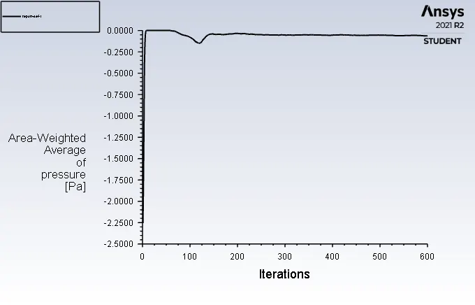
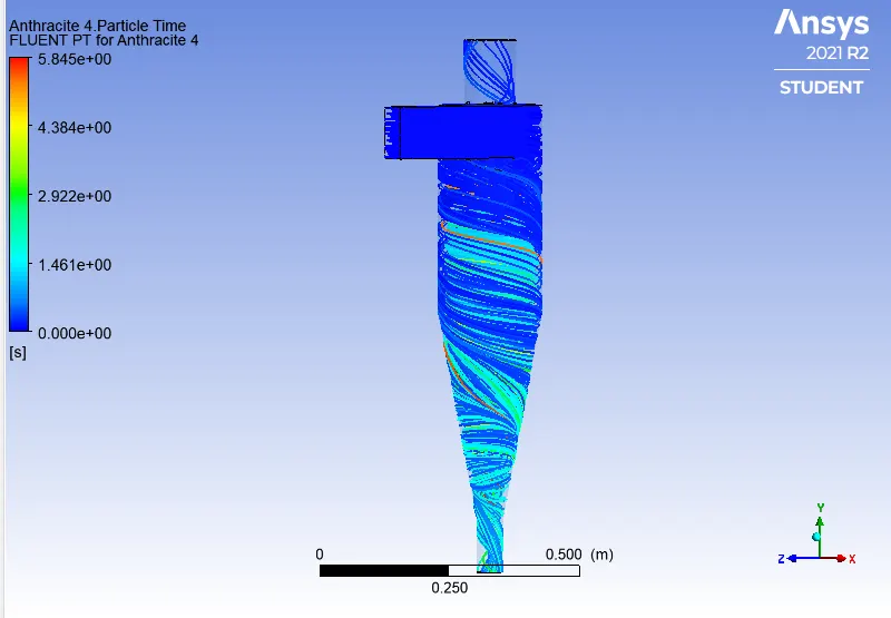
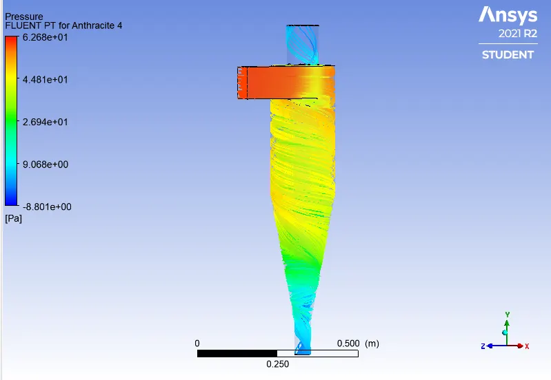
Case: B5
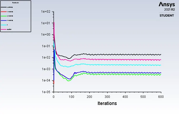
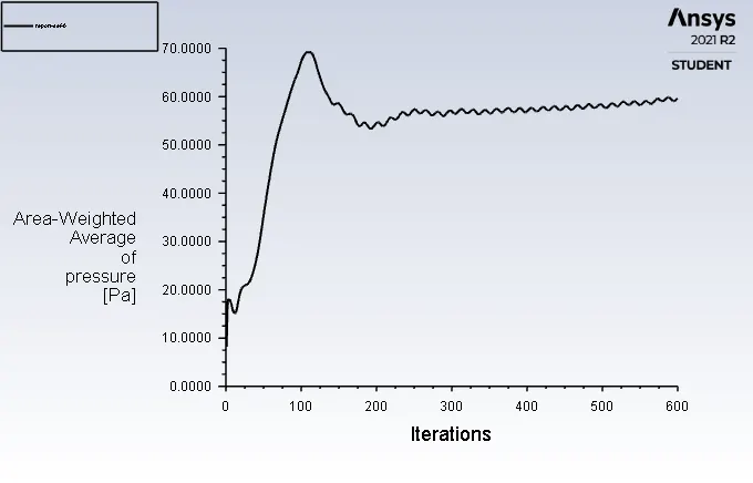
Separation Efficiency = (No. of Particles Trapped)/ (No. of Particles Tracked)
Separation Efficiency = (339/378)*100
Separation Efficiency = 89.68%
Pressure drop = Pressure at Inlet - Pressure at Oulet
Pressure Drop = 1.8489 - 0.6323
Pressure Drop =1.2166 pa
COMPARISON BETWEEN THE RESULTS FOR PART_A AND PART_B:-
| Divisions | Cases | X velocity (m/s) | Diamter of Particle(μm) |
Particle Tracked | Particle Traped | Separation Efficiency(%) |
Pressure Drop (pa) |
| Part A | A1 | 3 | 1e-6 | 378 | 259 | 68.51 | 1.7016 |
| A2 | 3 | 2e-6 | 378 | 274 | 72.24 | 1.7016 | |
| A3 | 3 | 3e-6 | 378 | 299 | 79.10 | 1.7016 | |
| A4 | 3 | 4e-6 | 378 | 321 | 84.92 | 1.7016 | |
| A5 | 3 | 5e-6 | 378 | 352 | 93.92 | 1.7016 | |
| Part B | B1 | 1 | 5e-6 | 378 | 189 | 50 | 1.8482 |
| B2 | 2 | 5e-6 | 378 | 323 | 85.94 | 1.8431 | |
| B3 | 3 | 5e-6 | 378 | 330 | 87.30 | 1.7016 | |
| B4 | 4 | 5e-6 | 378 | 334 | 88.35 | 1.8198 | |
| B5 | 5 | 5e-6 | 378 | 339 | 89.68 | 1.2166 |
Conclusion:-
- From the above Table we can see that the Efficiency of cyclone Separator is increased with the Diameter of Particle and Velocity is increases.
- In Part_A we can see that the Efficiency increases in gradual manner with increase in the diameter of Particles It is Because the larger the Particle diameter higher Inertia, hence chance of escaping the Particle's is reduced.
- In Part_B we can observe that the Separation Efficiency Increases rapidly with increase in the Velocity but in the Pressure Drop It may varry because The total pressure drop in a cyclone will be due to the entry and exit losses, and friction and kinetic energy losses in the cyclone. Normally most significant pressure drop occurs in the body due to swirl and energy dissipation.
- Particle Resident time for both the cases Part_A and Part_B decreases with Increase in the Diameter of Particle and injection Velocity of Particles.
- We can see that in the Pressure contours for all cases velocity is high at the Inlet, It is because the Particle are Injected forcefully by the Inlet.
- In the Pressure Contours we can Also see that Pressure is high at Inlet and the Outer surface of the Cyclone Separator and Low at the Bottom of the Cyclone Separator It is because, when the Particle's travles in the swirl motion from the Inlet to the bottom the centrifugal force imparted at the outer surface of the cyclone and then the Particle's thrown from axial to radial direction and dur to that pressure at the Outer surface is more.
- From the above Study we can Conclude that the Higher the Velocity, Higher the Pressure Drop and the Highest the Efficiency.