Week 8 - Simulating Cyclone separator with Discrete Phase Modelling
SIMULATING CYCLONE SEPARATOR WITH DISCRETE PHASE MODELLING
AIM:-
To perform analysis on cyclone separator and calculate the separation efficiency and pressure drop.
OBJECTIVE:-
- To write a few words about any four empirical models used to calculate the cyclone separator efficiency.
- To perform an analysis on a given cyclone separator model by varying the particle diameter from 1 μm to 5 μm and calculate the separation efficiency in each case. Discuss the results. [Use both the velocity's as 3m/sec.]
- To perform an analysis on a given cyclone separator model by varying the particle velocity from 1 m/sec to 5 m/sec and calculate the separation efficiency and pressure drop in each case. Discuss the results. [Using particle diameter size as 5 μm for all cases & keep flow velocity same as particle velocity]
INTRODUCTION:-
Cyclone separator:- Cyclone separators are separation devices (dry scrubbers) that use the principle of inertia to remove particulate matter from flue gases and fluids. Cyclone separators is one of many air pollution control devices known as precleaners since they generally remove larger pieces of particulate matter. This prevents finer filtration methods from having to deal with large, more abrasive particles later on. The separation process depends not only on the particle size but also on the density of particles. Depending on the fluid velocity, the cyclone separator can be used to separate all types of particles. It is also possible to allow fine particles to be carried by the fluid.
The construction of a cyclone separator is shown in Figure 1. It consists of a short vertical, cylindrical vessel with a conical base. The upper part of the vessel is fitted with a tangential inlet. The outlet (solid outlet) is arranged at the base. A fluid outlet is provided at the center of the top portion, which extends inwardly into the separator. Such an arrangement prevents the air from short-circuiting directly from the inlet to the outlet of the fluid.
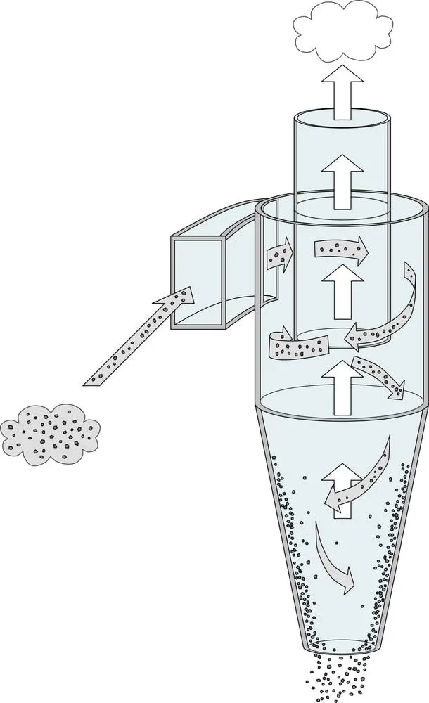 |
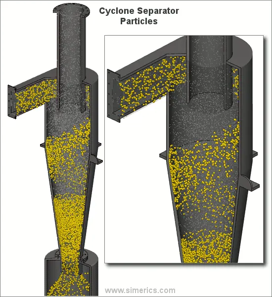
Cyclone separators work much like a centrifuge, but with a continuous feed of dirty air. In a cyclone separator, dirty flue gas is fed into a chamber. The inside of the chamber creates a spiral vortex, similar to a tornado. This spiral formation and the separation is shown in Figure 2. The lighter components of this gas have less inertia, so it is easier for them to be influenced by the vortex and travel up it. Contrarily, larger components of particulate matter have more inertia and are not as easily influenced by the vortex.
Since these larger particles have difficulty following the high-speed spiral motion of the gas and the vortex, the particles hit the inside walls of the container and drop down into a collection hopper. These chambers are shaped like an upside-down cone to promote the collection of these particles at the bottom of the container. The cleaned flue gas escapes out the top of the chamber.
 |
Most cyclones are built to control and remove particulate matter that is larger than 10 micrometers in diameter. However, there do exist high efficiency cyclones that are designed to be effective on particles as small as 2.5 micrometers. As well, these separators are not effective on extremely large particulate matter. For particulates around 200 micrometers in size, gravity settling chambers or momentum separators are a better option.
Out of all of the particulate-control devices, cyclone separators are among the least expensive. They are often used as a pre-treatment before the flue gas enters more effective pollution control devices. Therefore, cyclone separators can be seen as "rough separators" before the flue gas reaches the fine filtration stages.
Uses of Cyclone Separator:-
1) A cyclone separator is used to remove the following particulate matter from flue gases.
- Toxic particles
- Abrasive particles
- Coolant mists
- Metalworking chips
- Explosive particulate
- Fine powders
- Other production plant exhaust
2) It is also used for the size separation of solids in liquids.
3) It is used for separating the heavy or coarse fraction from fine dust.
Empirical models used to calculate the cyclone separator efficiency are.
1) Iozia and Leith model-
Iozia and Leith logistic model is a modified version of Barth Model, which is developed based on force balance. The model assumes that a particle carried by the vortex endures the influence of two forces: a centrifugal force, Z and a flow resistance, W. The collection efficiency ηi of particle diameter dpi can be calculated.
2) Li and Wang Model-
The Li and Wang model includes particle bounce or reentrainment and turbulent diffusion at the cyclone wall. A two dimensional analytical expression of particle distribution in the cyclone is obtained. Li and Wang model was developed based on the following assumptions:
- The radial particle velocity and the radial concentration profile are not constant for uncollected particles within the cyclone.
- Boundary conditions with the consideration of turbulent diffusion coefficient and particle bounce reentrainment on the cyclone wall.
- The tangential velocity is related to the radius of cyclone.
3) Koch and Licht Model
Koch and Licht collection theory recognized the inherently turbulent nature of cyclones and the distribution of gas residence times within the cyclone. Koch and Licht described particle motion in the entry and collection regions with the additional following assumptions:
- The tangential velocity of a particle is equal to the tangential velocity of the gas flow, i.e. there is no slip in the tangential direction between the particle and the gas.
- The tangential velocity is related to the radius of cyclone.
4) Lapple Model
Lapple model was developed based on force balance without considering the flow resistance. Lapple assumed that a particle entering the cyclone is evenly distributed across the inlet opening. The particle that travels from inlet half width to the wall in the cyclone is collected with 50% efficiency.
Geometry:-
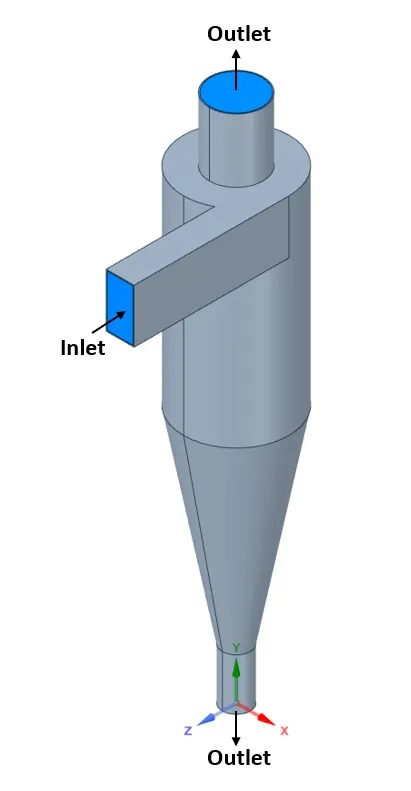
- The below figure is the geometry of a Cyclone separator we need to extract fluid domain from it'
- Blue region is the extracted fluid domain inside the Cyclone separator.
- It contains 1 inlet and 2 outlets as shown in below figure.
 |
Meshing:-
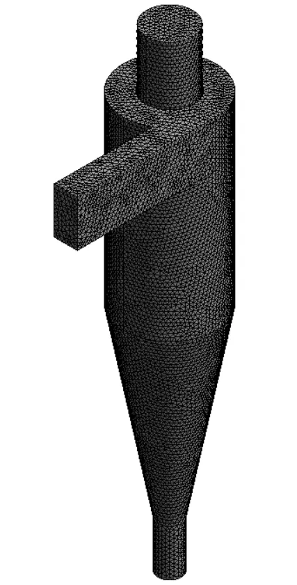
Here we need to name the boundaries using named selection option as inlet and outlet. Then we need to generate mesh as shown in below figure.
Element size --> 8 mm
Mesh method --> All triangle method
Number of Nodes --> 37020
Number of Elements --> 184967
 |
Setup:-
--> Models:-
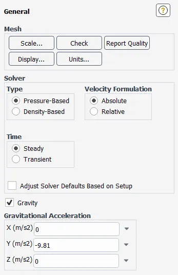
- Here we need to setup a solver. The solver type is pressure based, steady state and absolute velocity formation as shown in below figure and gravity in y-direction.
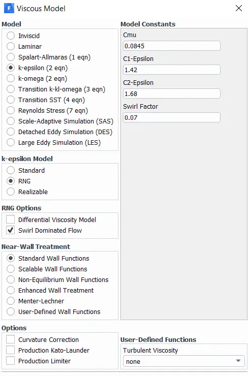
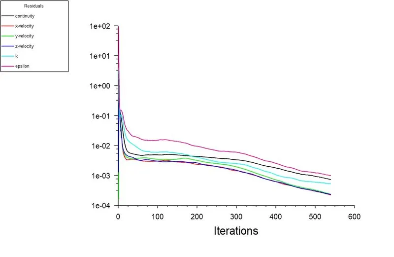
- After the solver setup we need to select K-epsilon RNG model, then we need to select Swirl Dominanted flow as shown in below figure.
 |
 |
-->Discrete Phase Model:-
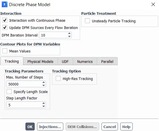
- After selecting Viscous model we need to select the Discrete phase model as shown in below figure
 |
- After creating DPM we need to create a injection which is releasing from inlet, the settings are shown in bellow table
- X-Velocity and diameter of injection changes according to the different cases we are solving.
| Injection type | Surface |
| Release from surface | Inlet |
| Particle type | Inert |
| Material | Anthracite |
| Diameter distribution | Uniform |
| Total flow rate (kg/s) | 1e-20 |
--> Boundary conditions:-
| Zone | Boundary condition | Discrete Phase Boundary condition type |
| Inlet | Velocity magnitude= 3m/s | Reflect |
| Outlet top | Guage pressure= 0 pascal | Escape |
| Outlet bottom | Guage pressure= 0 pascal | Trap |
--> Solution initializtion:-
- After creating injections and boundary condition we need to initialize the solution using Standard initialization and computing from Inlet.
PART 1:- To perform an analysis on a given cyclone separator model by varying the particle diameter from 1 μm to 5 μm and to calculate the separation efficiency in each case using both the velocity's as 3m/sec.
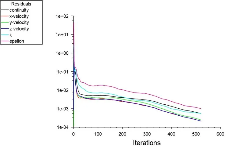
Case 1:- Particle Diameter = 1 μm
|
Separator efficiency:- Number of partcles trapped/ Number of particles tracked = (73/156) X 100 = 46.7% |
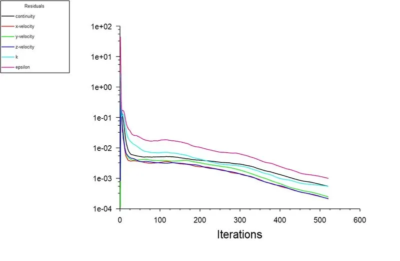

- Pressure and Particle time
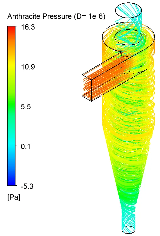 |
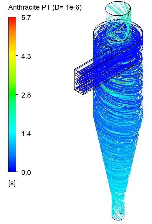 |
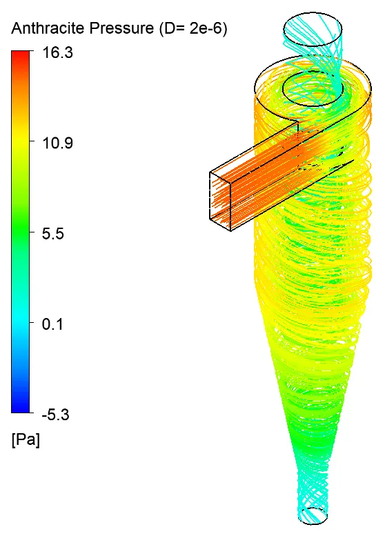
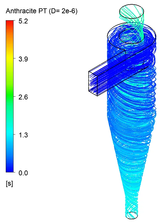
Case 2:- Particle Diameter = 2 μm
|
Separator efficiency:- Number of partcles trapped/ Number of particles tracked = (112/156) X 100 = 71.79% |

- Pressure and Particle time
 |
 |
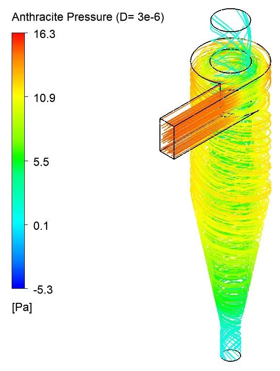
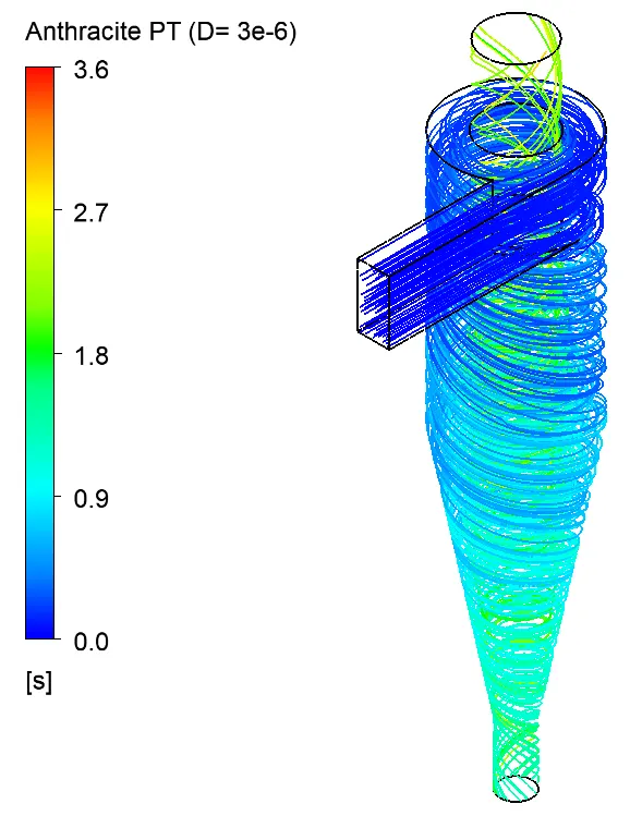
Case 3:- Particle Diameter = 3 μm
|
Separator efficiency:- Number of partcles trapped/ Number of particles tracked = (120/156) X 100 = 76.9% |

- Pressure and Particle time
 |
 |
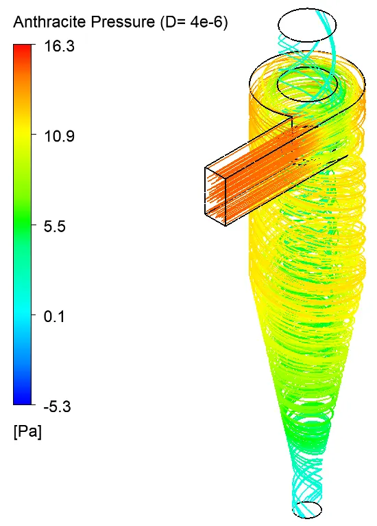
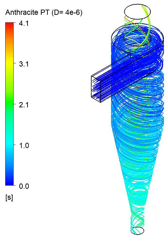
Case 4:- Particle Diameter = 4 μm
|
Separator efficiency:- Number of partcles trapped/ Number of particles tracked = (131/156) X 100 = 83.9% |

- Pressure and Particle time
 |
 |
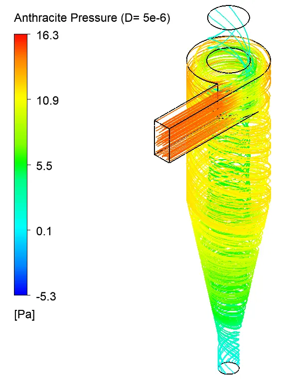
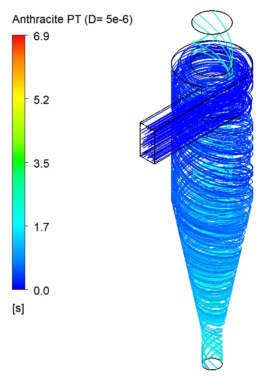
Case 5:- Particle Diameter = 5 μm
|
Separator efficiency:- Number of partcles trapped/ Number of particles tracked = (142/156) X 100 = 91% |

- Pressure and Particle time
 |
 |
| Particle size (μm) | Particle velocity (m/s) | Particles tracked | Particles escaped | Particles trapped | Particles incomplete | Seperator efficiency (%) |
| 1 | 3 | 156 | 49 | 73 | 34 | 46.7 |
| 2 | 3 | 156 | 40 | 112 | 4 | 71.79 |
| 3 | 3 | 156 | 32 | 120 | 4 | 76.9 |
| 4 | 3 | 156 | 22 | 131 | 3 | 83.9 |
| 5 | 3 | 156 | 12 | 142 | 2 | 91 |
PART 2:- To perform an analysis on a given cyclone separator model by varying the particle Velocity from 1 m/sec to 5 m/sec and to calculate the separation efficiency and pressure drop in each case Using particle diameter size as 5 μm for all cases & keeping flow velocity same as particle velocity.
Case 6:- Particle Velocity = 1 m/sec
|
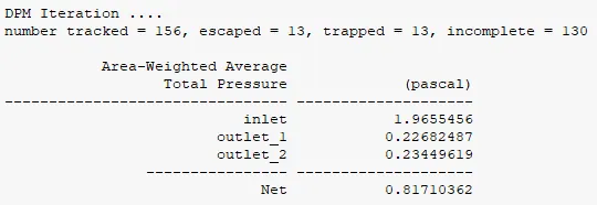
Separator efficiency= Number of partcles trapped/ Number of particles tracked = (13/156) X 100 = 8.3% Pressure Drop= Total inlet Pressure (inlet) - Total outlet Pressure (outlet_1) = 1.9655 - 0.2268 = 1.7386 Pascal |
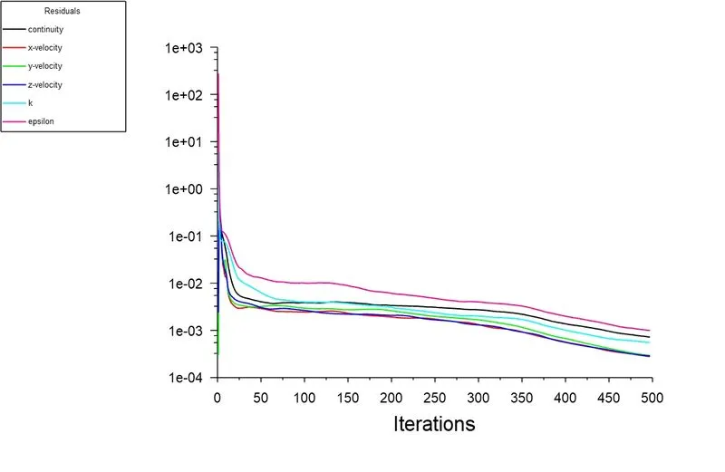
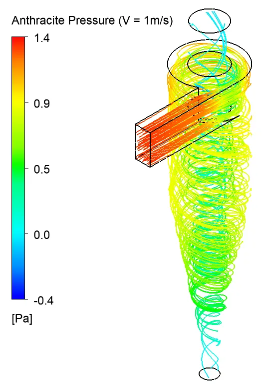
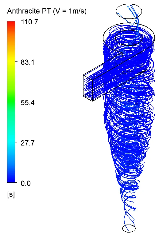
- Pressure and Particle time
 |
 |
Case 7:- Particle Velocity = 2 m/sec
|
Separator efficiency:- Number of partcles trapped/ Number of particles tracked = (9/156) X 100 = 7.7% Pressure Drop= Total inlet Pressure (inlet) - Total outlet Pressure (outlet_1) = 8.909 - 1.208 = 7.701 Pascal |
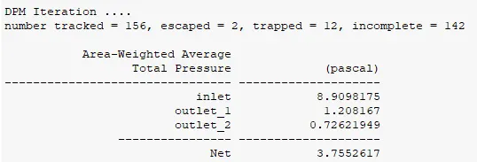
- Pressure and Particle time
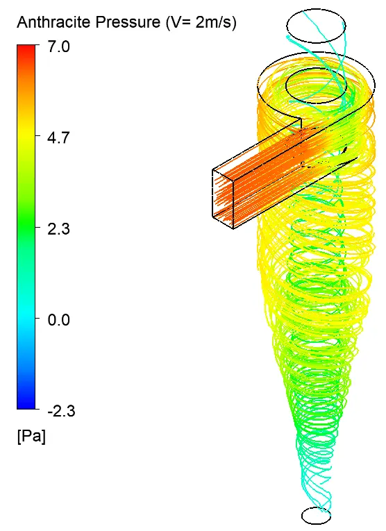 |
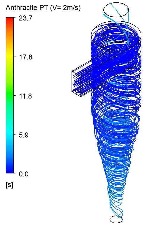 |
Case 8:- Particle Velocity = 3 m/sec
|
Separator efficiency:- Number of partcles trapped/ Number of particles tracked = (142/156) X 100 = 91% Pressure Drop= Total inlet Pressure (inlet) - Total outlet Pressure (outlet_1) = 20.463 - 2.8864 = 17.57 Pascal |
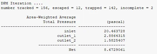
- Pressure and Particle time
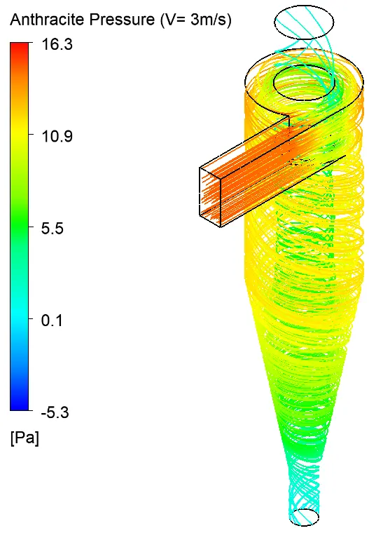 |
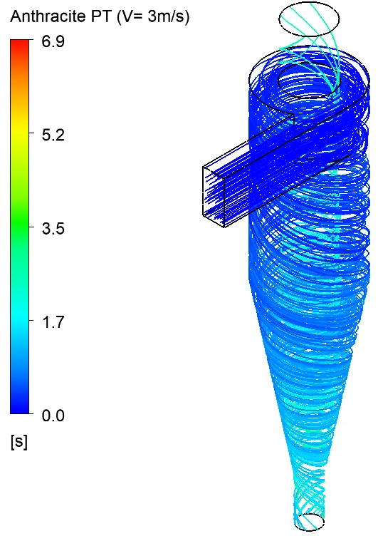 |
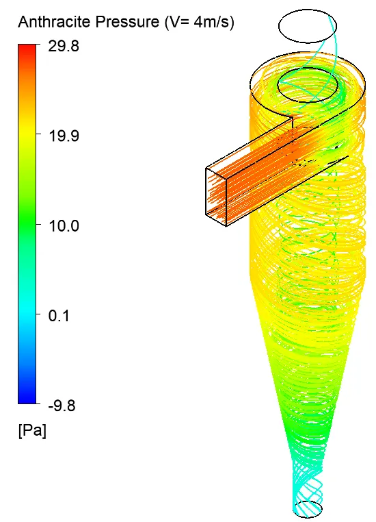
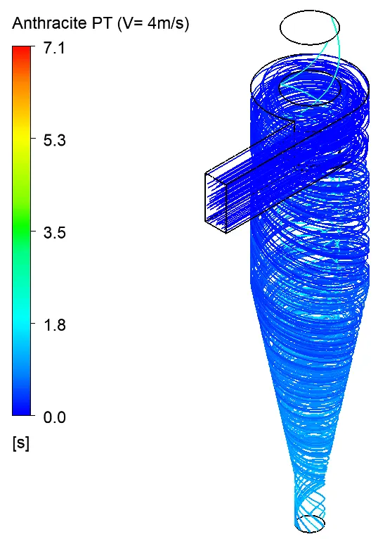
Case 9:- Particle Velocity = 4 m/sec
|
Separator efficiency:- Number of partcles trapped/ Number of particles tracked = (152/156) X 100 = 97.4% Pressure Drop= Total inlet Pressure (inlet) - Total outlet Pressure (outlet_1) = 37.0786 - 5.345 = 31.733 pascal |
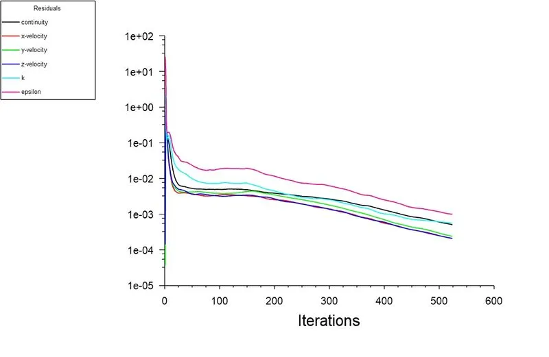
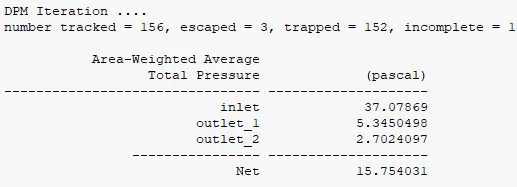
- Pressure and Particle time
 |
 |
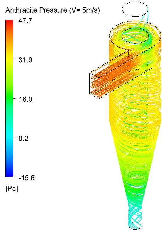
Case 10:- Particle Velocity = 5 m/sec
|
Separator efficiency:- Number of partcles trapped/ Number of particles tracked = (73/156) X 100 = 97.4% Pressure Drop= Total inlet Pressure (inlet) - Total outlet Pressure (outlet_1) = 58.8634 - 8.5693 = 50.294 pascal |
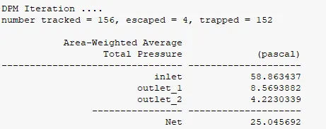
- Pressure and Particle time
 |
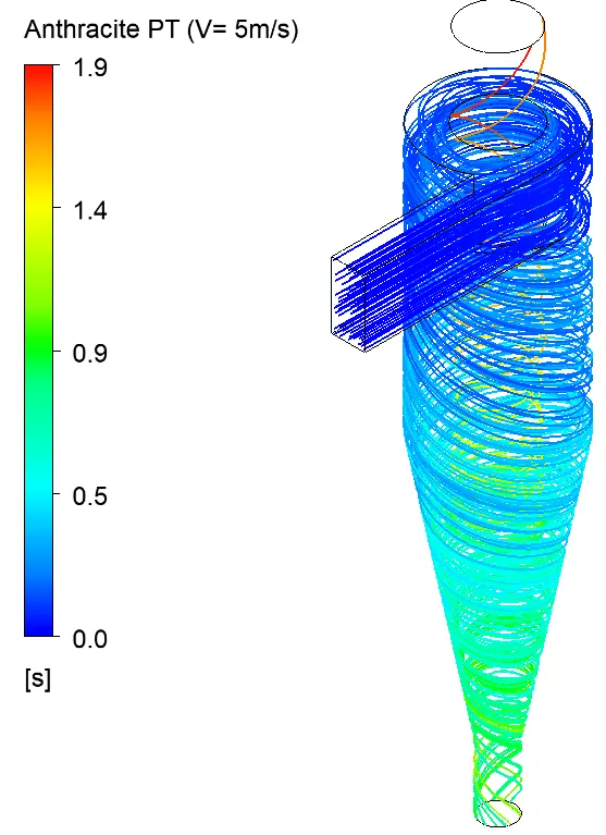 |
|
Particle velocity (m/s) |
Particle size (μm) | Particles tracked | Particles escaped | Particles trapped | Particles incomplete | Seperator efficiency (%) | Pressure drop (pascal) |
| 1 | 5 | 156 | 13 | 13 | 130 | 8.3 | 1.7386 |
| 2 | 5 | 156 | 2 | 12 | 142 | 7.7 | 7.701 |
| 3 | 5 | 156 | 12 | 142 | 2 | 91 | 17.57 |
| 4 | 5 | 156 | 3 | 152 | 1 | 97.4 | 31.733 |
| 5 | 5 | 156 | 4 | 152 | 0 | 97.4 | 50.294 |
CONCLUSION:-
- From above results we can clearly see that separation efficiency depends on both diameter and velocity of the particles.
- In part 1 we can see that with the increase in Particle diameter the separation efficiency also increases.
- In part 2 we can see that as the particle and flow velocity increases the separator efficiency and pressure drop also increases.
- The time required to capture the last trapped particle is reduced with increase in inlet velocity.
- By using refined mesh we can get more accurate results.