Week 8 - Natural Convection-II
Aim: To build a switchboard model and to solve the model for natural convection.
Objective:
- To build the model as per the following information.
- To mesh the model with nonconformal meshing
- To solve the problem of natural convection.
Introduction
Low Voltage Control Panel:
Low voltage control panels, also known as LVCPs, are electrical switchboards used to control and distribute electrical power to various equipment and systems in buildings and industrial facilities. They typically operate at a voltage level below 1000 volts and are responsible for controlling and protecting electrical systems by monitoring and regulating voltage, current, and frequency.
LVCPs may include a variety of components, such as circuit breakers, relays, contactors, fuses, transformers, and meters, all of which work together to ensure that electrical systems operate efficiently and safely. These panels can be custom-designed to meet specific needs and may be used for a wide range of applications, such as motor control, lighting control, power distribution, and HVAC systems control.
Circuit Breaker:
Circuit breakers are electrical devices that are designed to protect electrical circuits and equipment from damage due to overcurrent or short circuits. They are typically installed in electrical panels or switchboards and serve as a safety mechanism that automatically interrupts the flow of current in the event of an overload or fault.
Circuit breakers work by detecting an overcurrent or short circuit and quickly opening a switch to break the electrical connection, thereby preventing the current from flowing any further. This helps to protect the electrical system from damage and can prevent fires, explosions, and other safety hazards.
Circuit breakers are available in a range of sizes and ratings to accommodate different applications, from residential homes to industrial facilities. They may be designed to protect a single circuit or multiple circuits and can be operated manually or automatically. Some circuit breakers also have additional features, such as ground fault protection or arc fault detection, to further enhance safety.
Bus Bars:
Bus bars are a type of electrical conductor that is used in switchboards to distribute electrical power from the main power source to various pieces of electrical equipment. They are typically made of copper or aluminum and are designed to carry high currents with minimal energy loss.
In a switchboard, the bus bars serve as a central point for connecting various electrical components, such as circuit breakers, fuses, switches, and transformers. The bus bars are typically arranged in a common plane and may be insulated or enclosed in protective housing to prevent accidental contact.
Bus bars are preferred in switchboards for their high current carrying capacity, low resistance, and ease of installation. They are also more compact and efficient than traditional wiring systems, making them a popular choice in modern switchboards. Bus bars may be designed for various voltage levels, and their configuration and size can vary depending on the specific application and electrical load requirements.
To build the model as per the given information:
Geometry Creation of Bus Bars:
Creating bus bars for a switchboard using Ansys Icepak block objects is a straightforward process that involves defining the appropriate shape, dimensions, and material properties for the bus bar, and then connecting it to other components in the switchboard design as shown below:
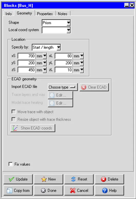
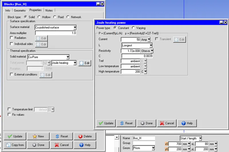
Similarly, Other Bus Bars were created.
Geometry Creation of Circuit Braker:
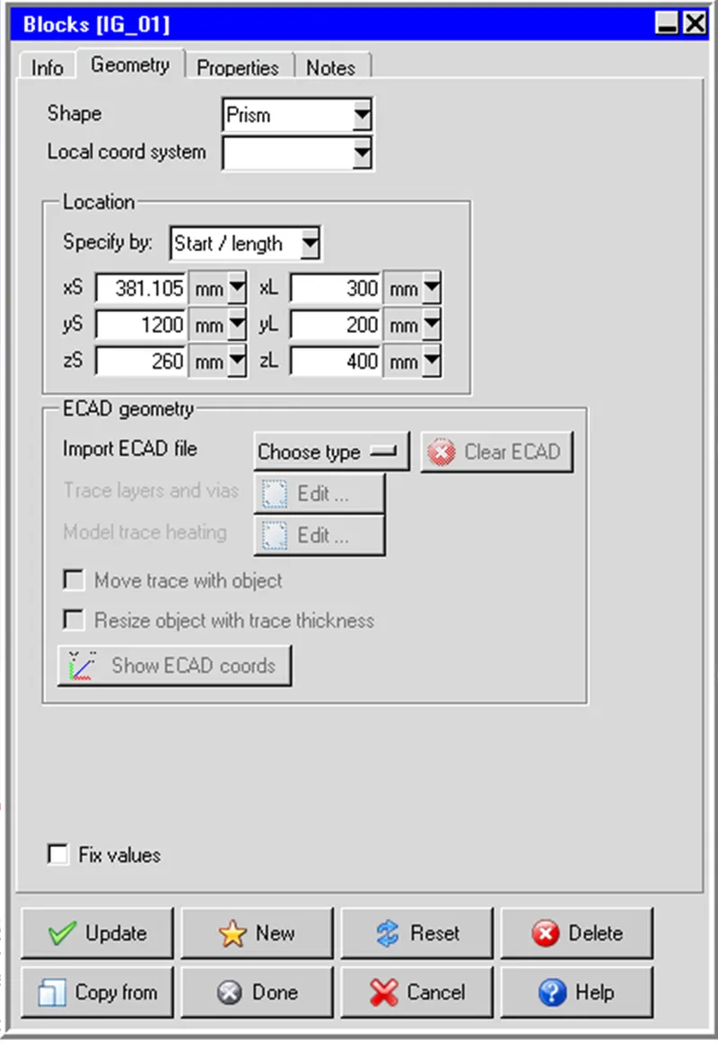
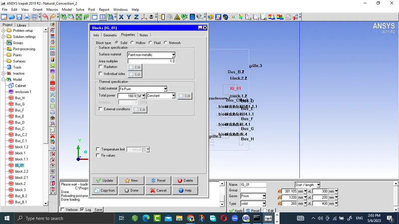
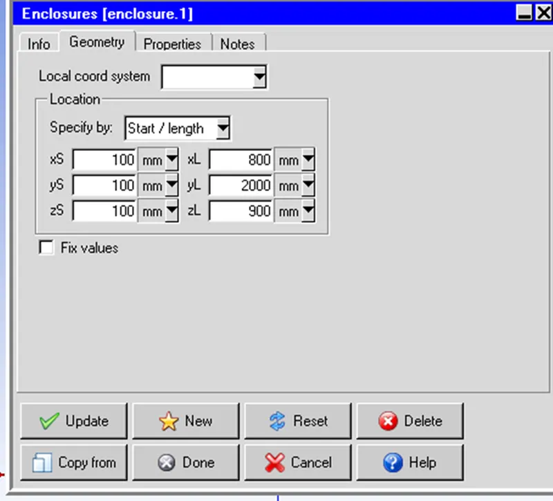
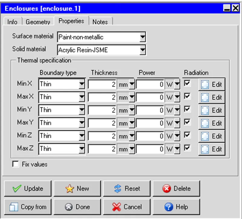
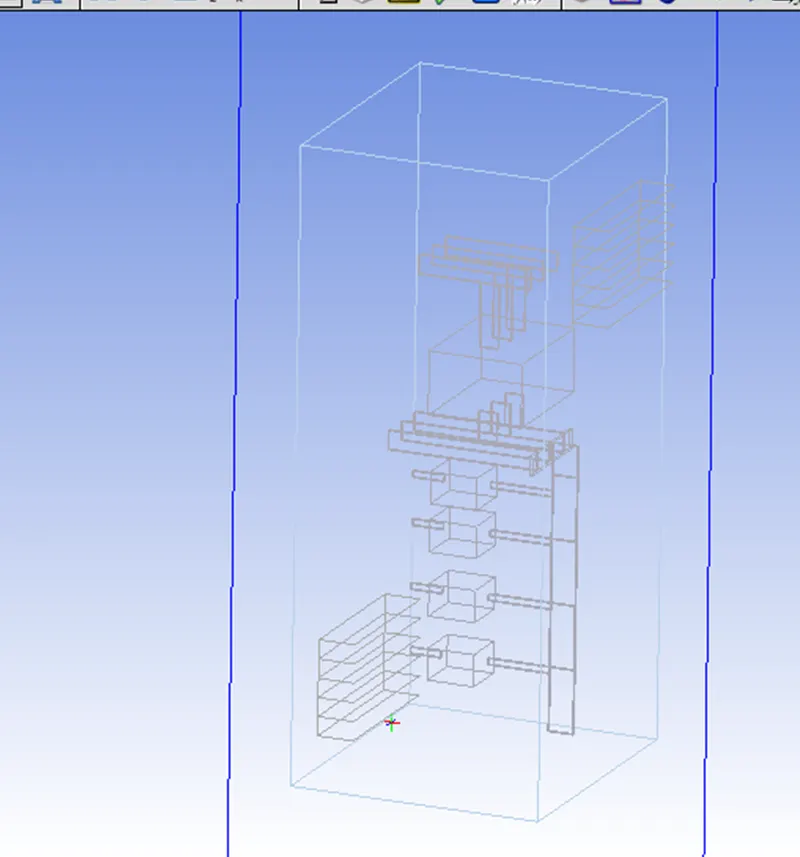
The complete Model created is shown below:
Meshing:
Non-conformal meshing is a meshing technique used in computational fluid dynamics (CFD) to connect two or more meshes with different topologies and resolutions. This approach allows for modeling complex geometries and multi-component domains that cannot be meshed with a single, uniform mesh.
In non-conformal meshing, each mesh is created independently, and the meshes are then connected at the boundaries using special techniques. The resulting mesh may have non-matching nodes and edges at the interfaces, which can create challenges in accurately solving the fluid flow equations across the interface. To overcome these challenges, CFD solvers use special algorithms to handle the non-matching interfaces between the meshes, such as interpolation of data across the interface or the use of ghost cells to approximate the solution in the non-matching cells.
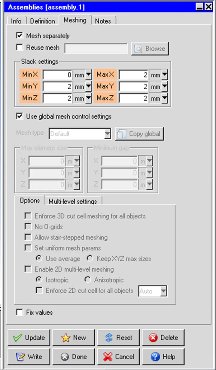
Similarly, other assemblies are defined.
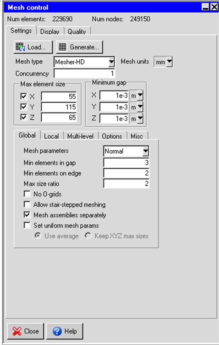
Mesh is generated by using the setting applied in the control panel given below:
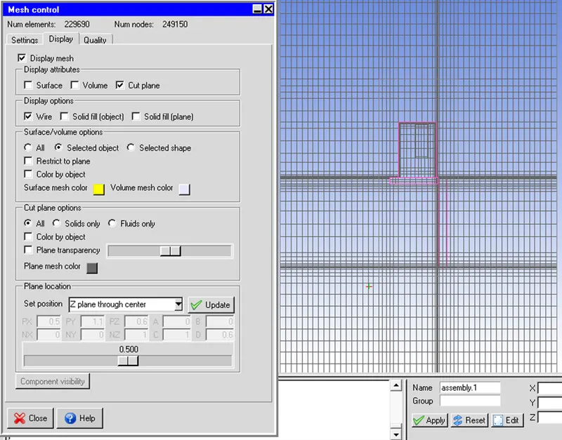
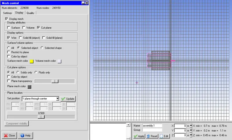
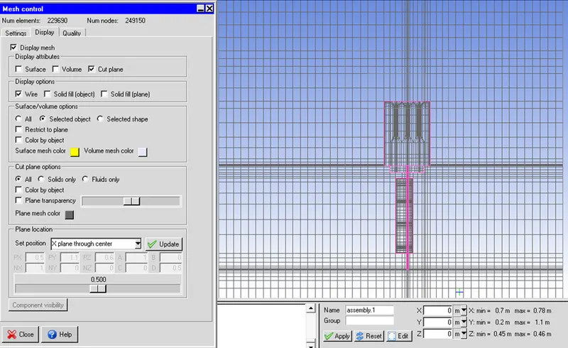
Mesh-cut plots on different planes
Z-Plane Through the Center
Y-Plane Through the Center
X-Plane Through the Center
Mesh Quality in terms of Skewness and face alignment is given below:
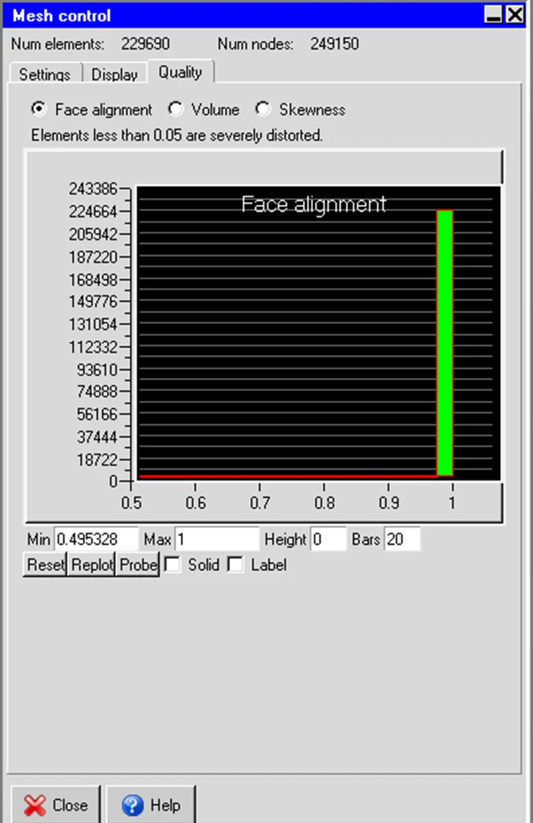
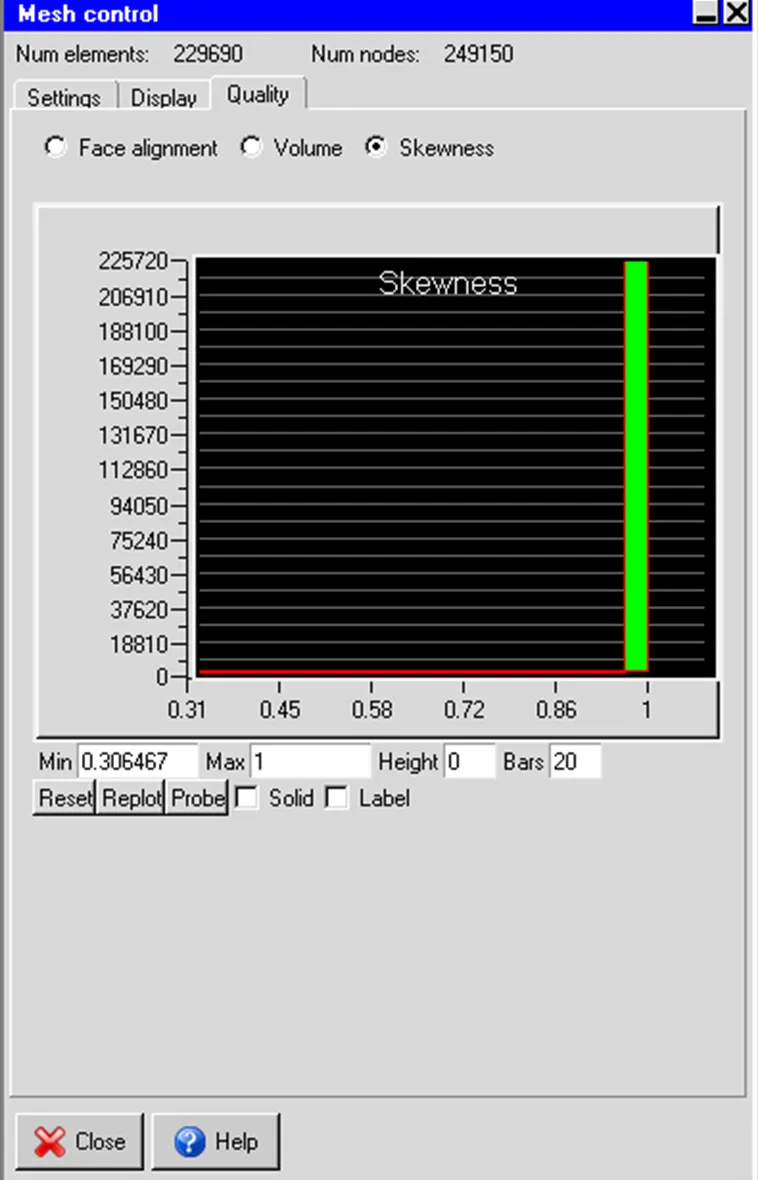
From visual inspection and mesh quality assessment by using skewness and face alignment, the above-generated mesh can be considered as a good quality mesh.
Solver Setting for Natural Convection:
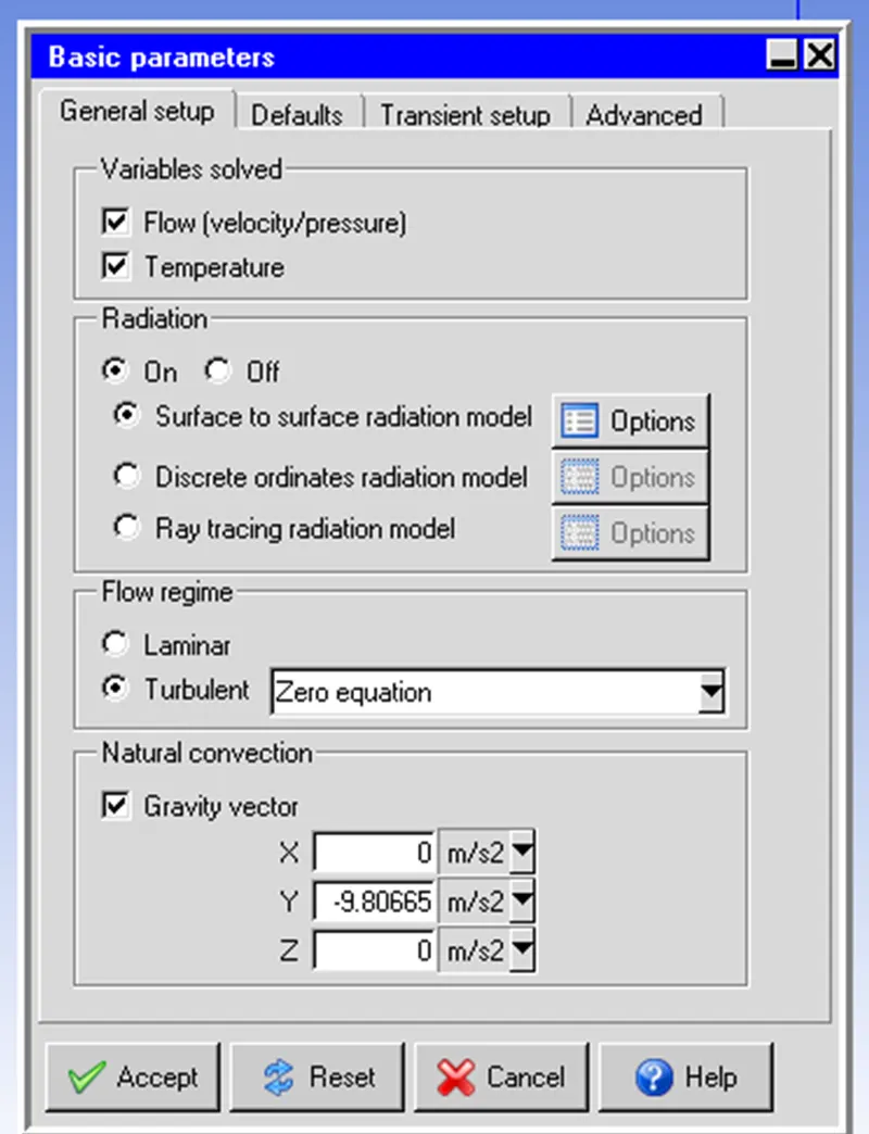
When modeling natural convection with radiation in Ansys Icepak, it is important to carefully consider these basic parameter settings to ensure accurate and reliable results.
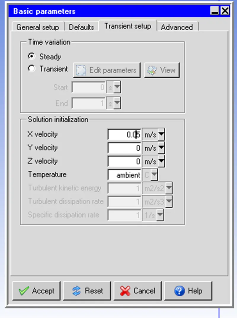
Basic Settings are given below:
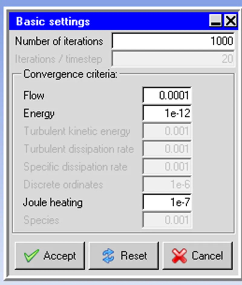
Convergence criteria: The convergence criteria specify the threshold for how small the residuals should be before the simulation is considered converged. Residuals represent the difference between the calculated values and the actual values for each equation being solved in the simulation. For natural convection simulations, a commonly used convergence criterion is to set the residuals to be less than 1e-4 or 1e-5.
The number of iterations: The number of iterations specifies how many iterations the solver should run before checking the convergence criteria. The number of iterations needed to reach convergence will depend on the complexity of the model and the level of accuracy required. In general, the more complex the model, the more iterations will be required to reach convergence.
Time step: The time step specifies the interval at which the solver calculates the solution. A smaller time step can improve the accuracy of the solution, but it will also increase the computational time required for the simulation.
Other settings are kept as default.
Results:
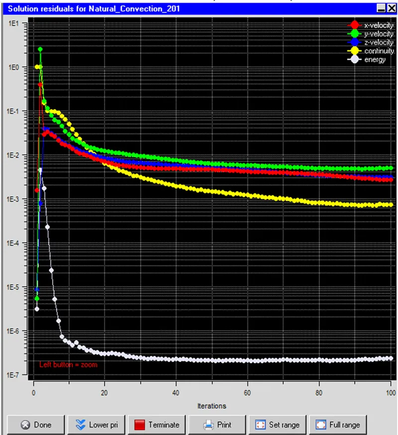
The solution residuals plot is a graphical representation of the convergence of the numerical solution during the simulation. It shows how the residuals, which are the differences between the calculated values and the actual values for each equation being solved in the simulation, change over the course of the simulation. In Ansys Icepak, the residual plot can be used to monitor the convergence of the solution and determine if additional iterations are needed to reach convergence.
For a natural convection model that includes an initial velocity of 0.05 m/s in the x-direction for a low-voltage electrical control panel, the solution residuals plot will provide important information about the convergence of the simulation. Ideally, the residuals plot should show a steady decrease in the residuals over time, indicating that the numerical solution is approaching a converged state.
However, if the residuals plot shows that the residuals are not decreasing or are oscillating around a certain value, this indicates that the solution has not yet converged and additional iterations are needed. The plot can be used to determine the appropriate convergence criteria and number of iterations needed to achieve an accurate and reliable solution.
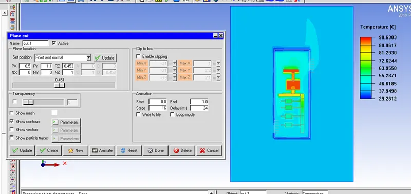
Temperature Contours for the cut plot for Plane Z passing through the center of the cabinet are shown below:
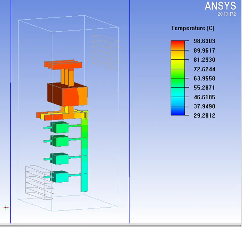
The maximum temperature reached is 98.6303 degree Celsius in the IG circuit breaker and Bus Bar B.
The entire cabinet is above room temperature.
Circuit breakers are designed to protect electrical circuits by interrupting the flow of current when a fault or overload is detected.
During normal operation, a circuit breaker should not get excessively hot. However, if the circuit breaker is repeatedly tripping due to an overload or a fault, or if it is not properly sized for the circuit it is protecting, it can generate heat. In the below case, poor ventilation may be the cause of the high temperature.
The face plot of the temperature contours is shown below:
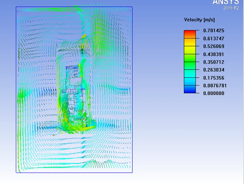
Velocity Vectors plot is shown below for plane Z passing through the cabinet center.
Velocity vectors play a crucial role in natural convection simulation by providing a visual representation of the fluid flow and aiding in the calculation of other important variables.
In natural convection simulation, velocity vectors are an important component because they describe the direction and magnitude of fluid flow due to buoyancy forces. Buoyancy forces are caused by density differences in the fluid, and in natural convection, these differences are usually due to temperature variations.
The maximum velocity achieved is 0.701425 m/s.
Conclusion:
As per the given information model is prepared and the model is solved for natural convection.
Providing adequate ventilation, over heating of the circuit breaker can be prevented.