Week - 8 - Morphing
Aim: to morph the given components according to the guidelines
for component 1 we can follow the video and make sufficient changes to it
for component two we need to morph the areas as shown in bellow figure:
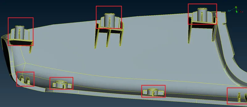
where we need to increase the height of the dog houses and ribs.
introduction:
MORPHING: it is a technique used in CAE software to change the geometry or modify the existing geometry to improve the results according to the analysis instead of waiting for the design team to do the work.in fact, it also saves time in the trial and error methods of the design team.
giving the morphed component to the design team will provide them with a better understanding of the area to be modified in cad software properly for production.
this morphing can be carried out on the component's geometry or FE of the elements.
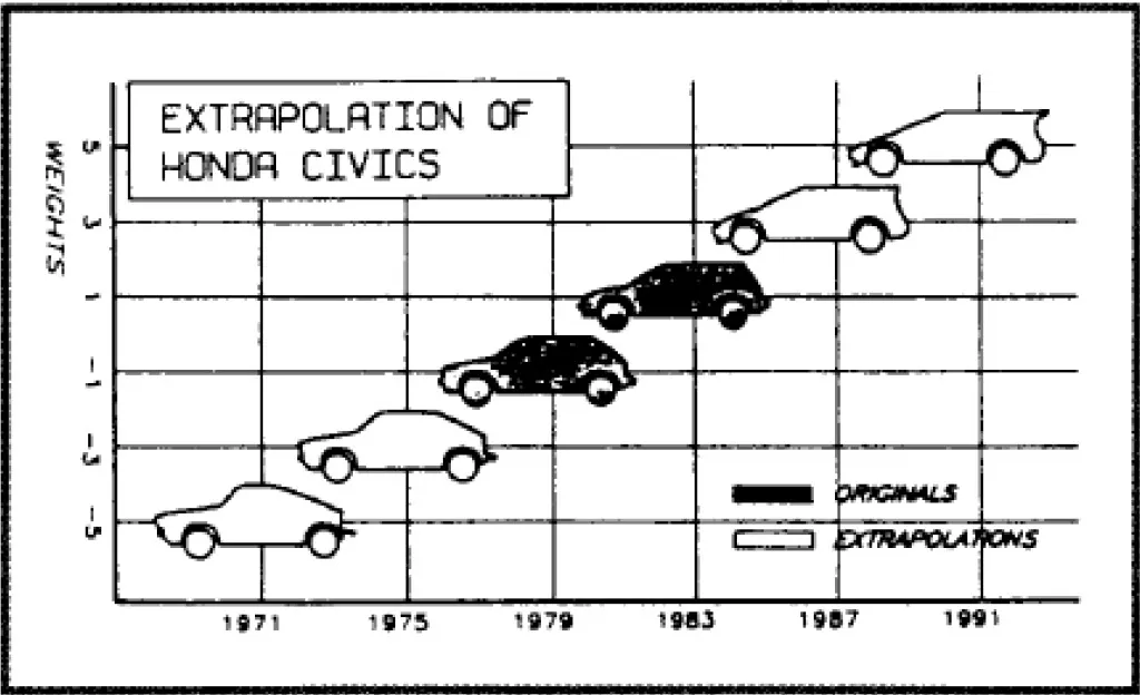
below figure explaines how the different models can be evoluted by morphing
component 1:
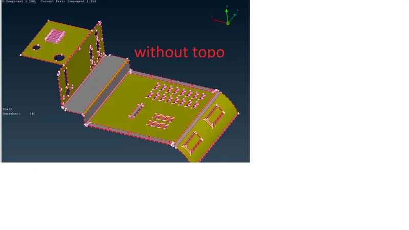
fig 1
the given components imported (file-open-choose the file location-select the file to import-open) are shown above
step 1
red lines indicating free edges i.e., no surfaces are connected with each other.therefore we need to perform topo(topology module-faces-topo-select all the surfaces edges to connect-ok)
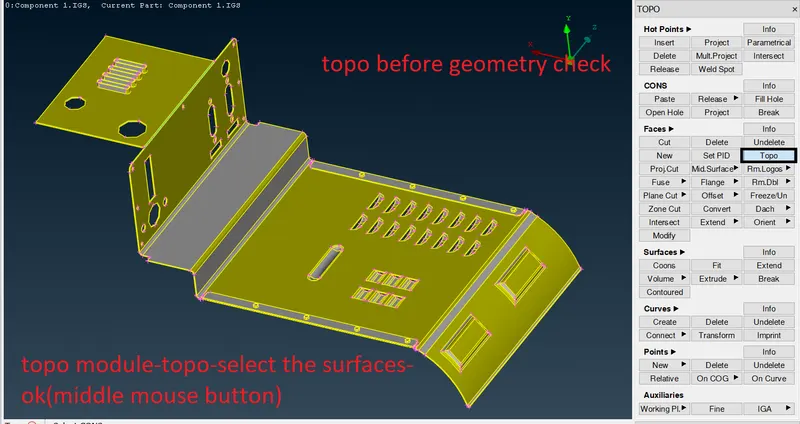
fig 2
here the yellow line indicates the joint of two surfaces.
- change the orientation of surfaces before going for a geometry check
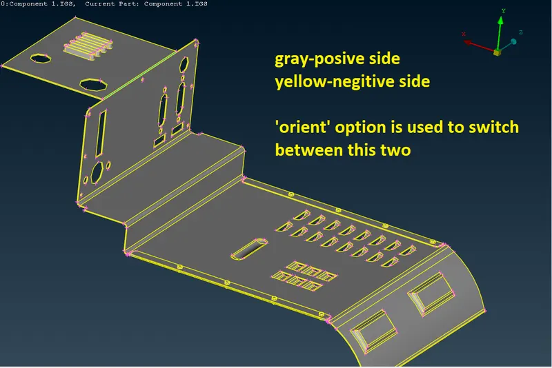
fig 3
step 2
- geometry check: In this, we can check geometrical errors that occurred on importing the component or while performing the topo option
- tools tab-checks(under down arrow)-geometry-select execute option in the new popup window-select all the errors -right-click on the errors selected -choose fix option to clear the errors automatically.
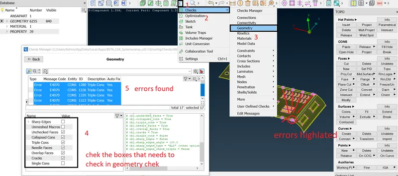
fig 4: errors ditected
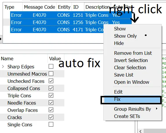
fig 5: automatic fixing of errors
- if the errors are not cleared automatically we need to solve them manually for that follow the below figures
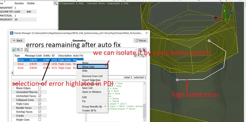
fig 6:highlating the errors by show only option
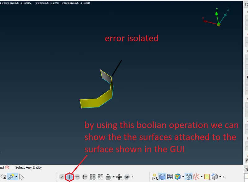
fig 7:isolated surface with error
- the blue line indicates the 'triple corn' which indicates the intersection of three surfaces.
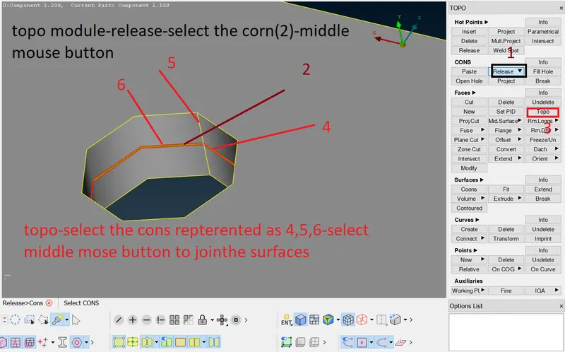
fig 7:
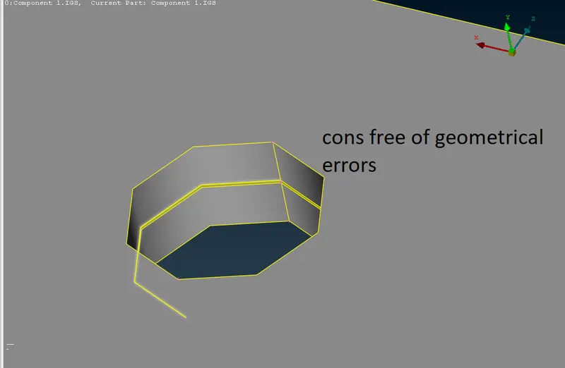
fig 8: error is cleared
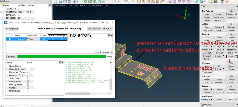
fig 9: surfaces with error-free
step 3:
MORPHING:
morphing is performed on the given component by using different options in the morph module. Therefore explanations and pictorial representations are shown below.
- opening morph module
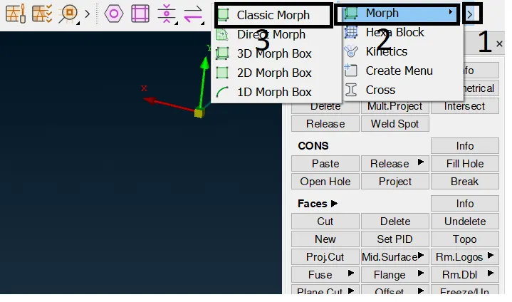
fig 9: morphing module
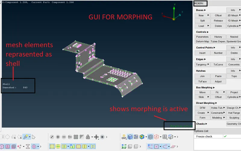
fig 10: GUI of morphing
- NEW:
- the portion of the geometry which we want to morph is need to be selected by using this new option which creates the box around the selected surfaces with nodes on the corners of the box and by manipulating the options between ortho/min..volume/align we can set the local coordinates of the morph box
- morph module-boxes-new-select the surfaces to morph-choose any of ortho(local co-ordinates align with global coordinate system)/min..volume(align the coordinate with geometry (or) surfaces)/align(can create user-defined coordinate system)-ok(middle mouse button)
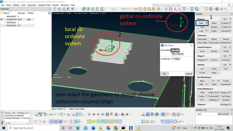
fig 11: creating morph volume box
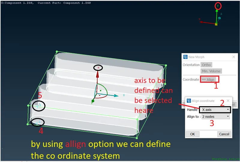
fig 12: use of align option
- MOVE:
- by using the move option we can morph the selected geometry into the desired shape, in the move option, we have more options like MVfree(move free)/translate/rotate/scale etc.
- mv free: option used to morph the geometry in the desired direction freely by moving the nodes also we can restrict the motion of nodes in a particular direction by unchecking the boxes as shown in the bellow figure.
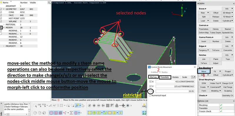
fig 13: performing 'Mvfree' option
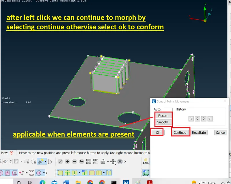
fig 14:
- translate: we can perform the translation of nodes only in the selected direction by providing a distance value
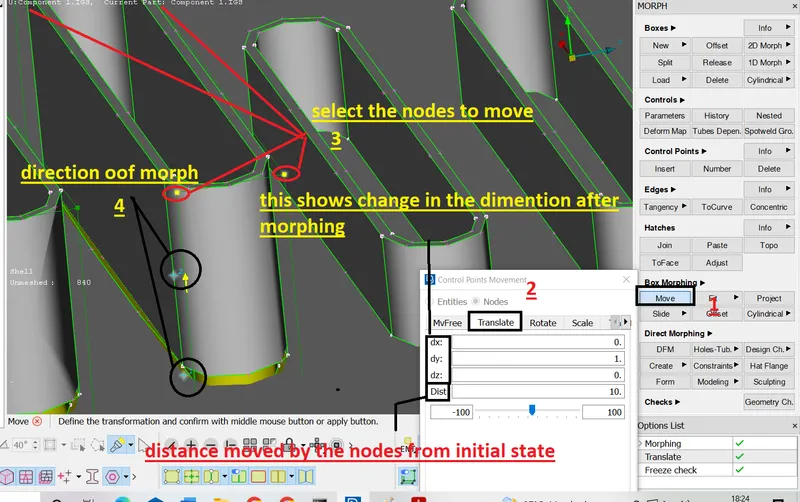
fig 15: translate option
- rotate: this is also used to chive rotational motion.
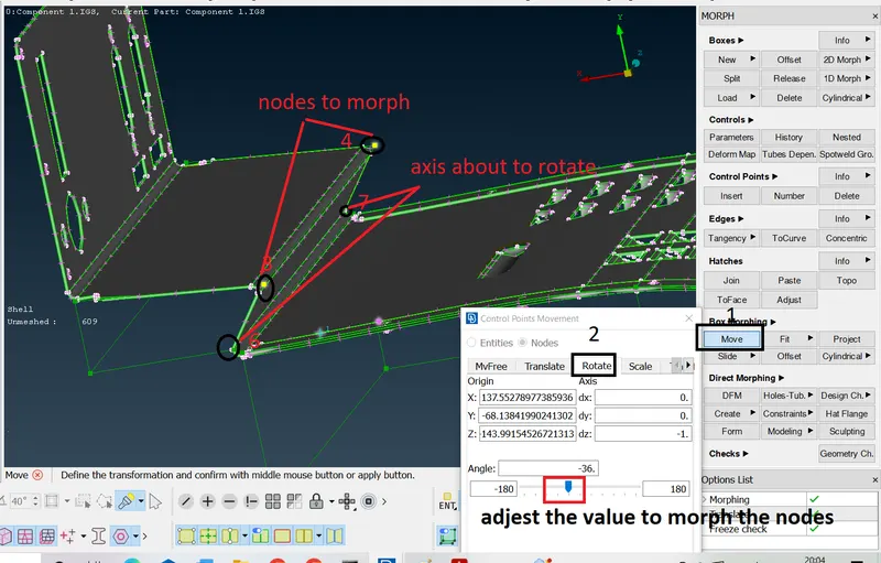
fig 16: rotate option
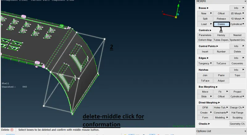
- DELETE:
- as the name suggstes we can delete the alredy created morph volumes
- boxes-delete-select the morph volume
INSERT:
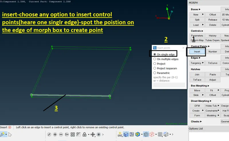
through this option we can insert the nodes on the edges
morph module-control points-insert-choose options as requred 'on single edge'.
on single edge:we can insert control points on single edge at once
on multiple edges: we can insert control points on multiple edges at a time.
project: control points can be projected on oposite edges
project isoparam: in this option points are created on the selected edges at equal distances only input is no.of points
parametric : points can be inserted at perticulat position based on the distance we provide (range from 0to 1)
split:
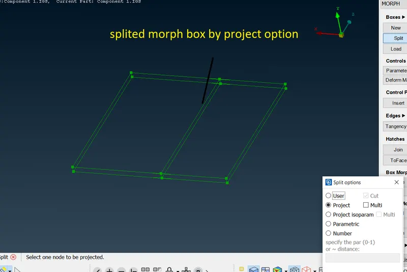
we can split the morph volume by using this option.
morph module-boxes-split-user(divides the box according to nodes specified by the user)/project(by selecting one node volume is divided atomatically)/project isoparam(divides hole box equally based on number of divisions)/parametric(divides the box by selecting one node division takes places by projecting the node perpendicularly to the opposite edge)/number.
over all morphing on component 1
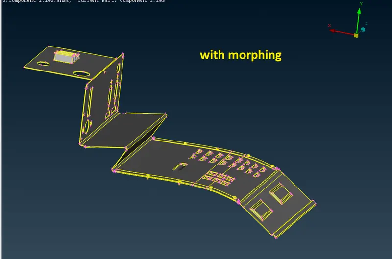
with marphing without morphing
component 2
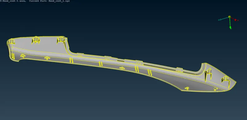
heare hand rest is provisded as our second component
step 1
importing the model
step 2:
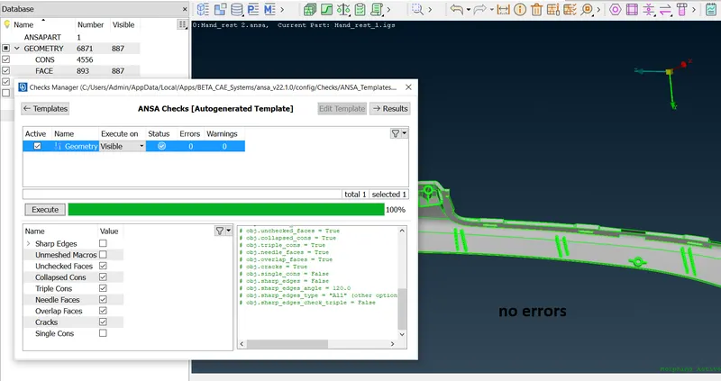
geometri check
step 3
morphing
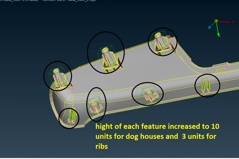
according to the guide lines we need to morph the dog houses and ribs
highlated features are need to increase theire hight
step 4
creating morph volume
- for every feature morph volumes are created as metioned above by using align becuse features morph diection coinsiding with global cordinates.
- boxes-new-select surfaces-align cor ordinates according to geometry.
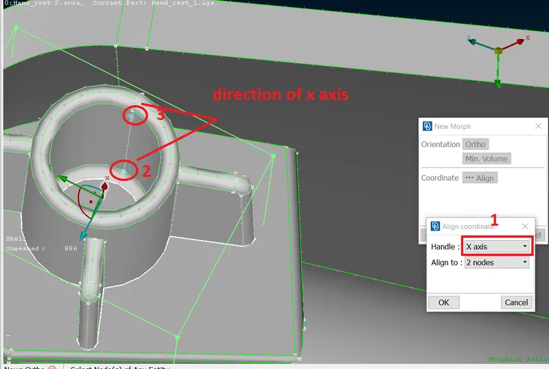
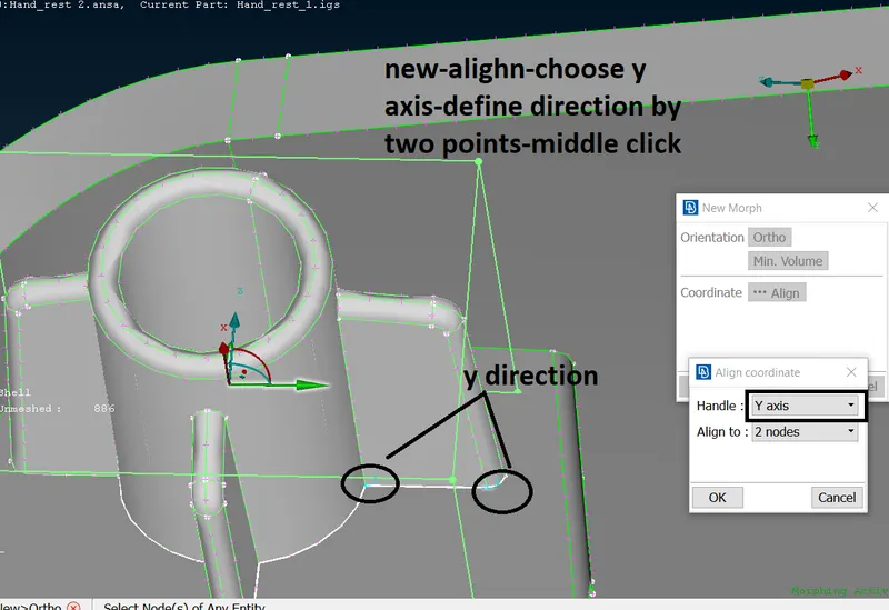
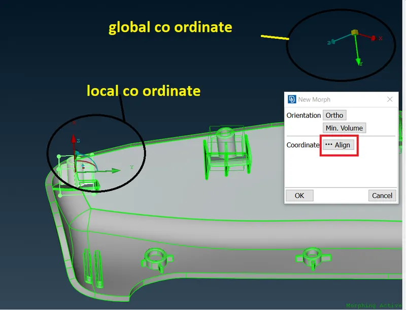
above figure shows the creation of morph volume by using align option.
step 2
translate option is used to increase the hight of dog houses
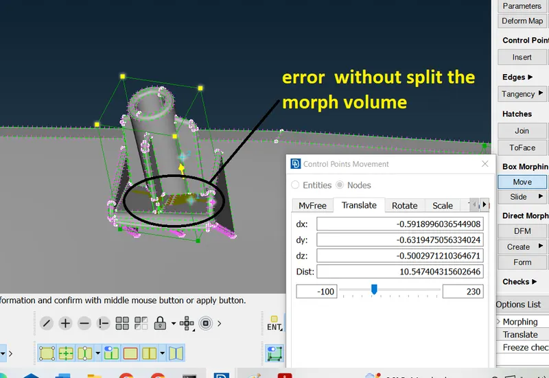
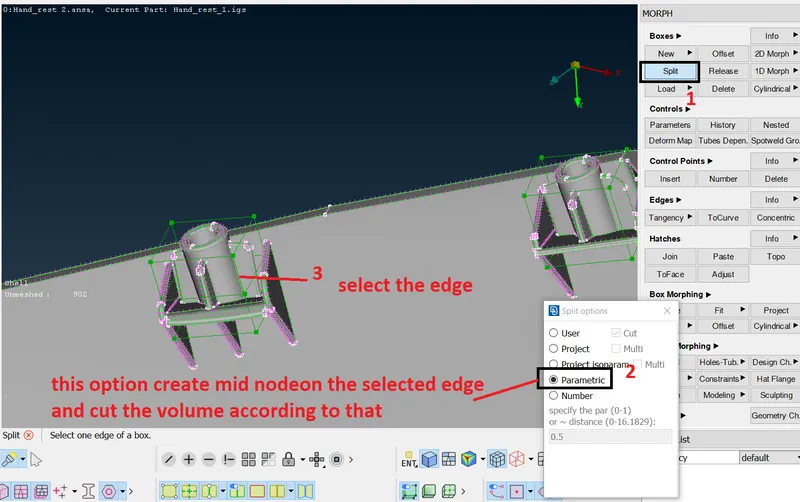
translation without spliting damaging the surfaces there fore split option is used to split the volume horizontally and tried to morph upper portion so that we can avoid surface distortion at bottom
below figure shows the splitting of volume using parametric option.
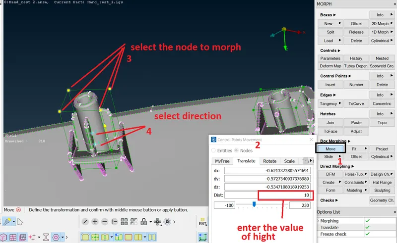
here dog houses hight is increase to 10 units.
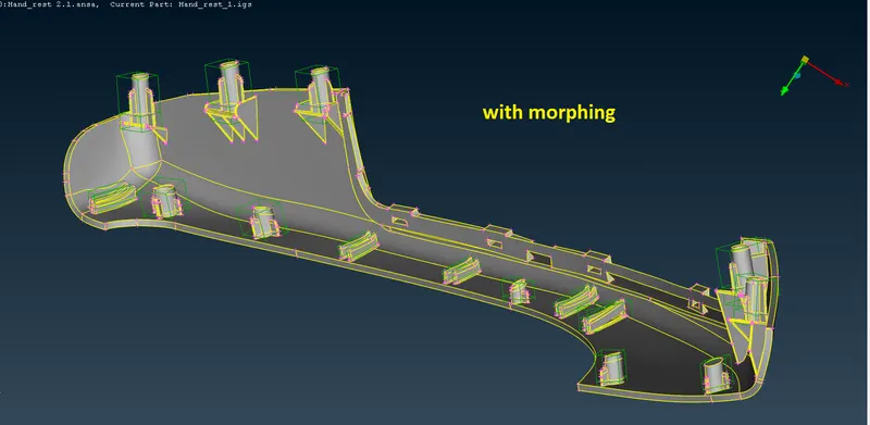
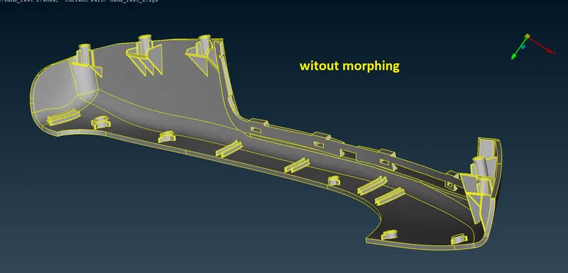
same rotien of creation of morph volume-splitting it to half-and performing translate option every festure the figuires bellow reprasents the same.
conclusion :
options lerned
- new(boxes-new-select surfaces-choose ortho/min..volume/align to set co ordinates)
- split(boxes-split-user/project/project isoparam/parametric/number)
- delete(boxes-select volumes/boxes to delete)
- insert(morph module-control points-insert-one single edge/multiple edge/project/project isoparam/parameteric)
- move(morph module-box morphing-move-select the nodes to move-choose MVfree/translate/rotate/scale etc)