Week 8 - Challenge 6 - Core & Cavity Design
Aim : Create the Core and cavity blocks for the switch bezel
Objective :
1.To Create the core block for switch bezel
2.To Create the cavity block for switch bezel
3.To Create parting line as well as parting surface also published it.
General Informations :
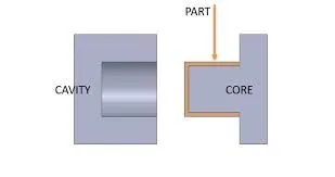
What is core and cavity in injection molding?
The core and cavity are the two halves of the mold where the hot molten plastic material is injected into the core and cavity and the gap between the core and cavity is filled with the hot molten material during the injection molding process and then hardened into the final shape.
The mold design of the core and cavity is critical to the proper molding of the product. The core is the raised part of the mold and the cavity is the recessed part of the mold.
The cavity and core in a typical plastic injection molding machine of an injection mold are the molding parts of the mold and play a key role in the shape of the molded part.
For some complex molds, the cavities or cores are often inserted, i.e., a part of them is removed from the cavity or core to form an insert structure, which is similar to the decomposition of cavities and cores.
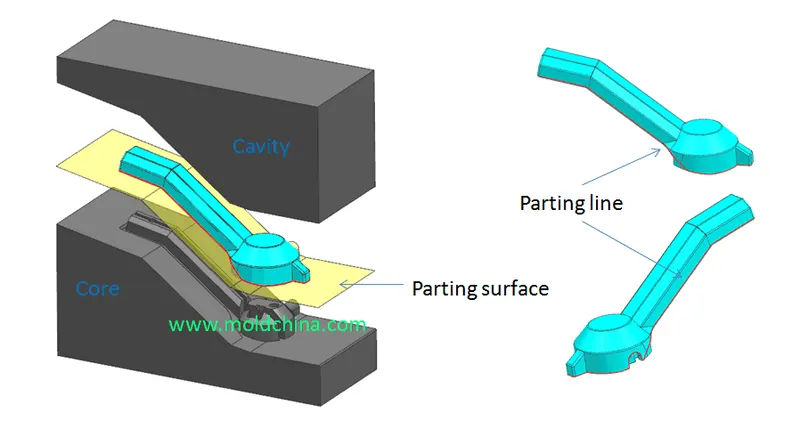
What is a parting line and what is a parting surface ?
Definition of parting line :
In injection moulding, the parting line is the line where the two halves of the mould come together.
In some cases, there may be more than one parting line, which can be used to create different appearances for the same moulded part.
However, multiple parting lines can also lead to increased mould wear and may require more frequent maintenance. Therefore, the location of parting lines must be carefully considered when designing injection moulded parts.
Definition of parting surface :
A parting surface is a separable contact surface that separates the mould to remove the product and the congealed material from the pouring system. A mould may have one or two or more parting surfaces depending on the need. The parting surface may be perpendicular to the closing direction, or parallel or inclined to the closing direction.
The parting surfaces provide support to the mould during the injection process and help to distribute the molten plastic evenly. It is important to design the parting line and parting face carefully to minimize potential defects in the moulded part.
Forms of parting surfaces In terms of the number of parting surfaces, there are single parting surfaces, double parting surfaces, and multiple parting surfaces.
In terms of the shape of the parting surfaces, there are flat, beveled, stepped, and curved surfaces.
Procedure for creatations of tooling axis :
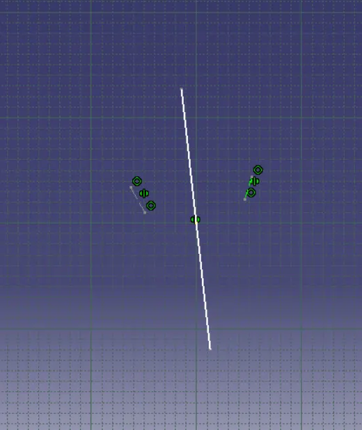
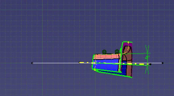
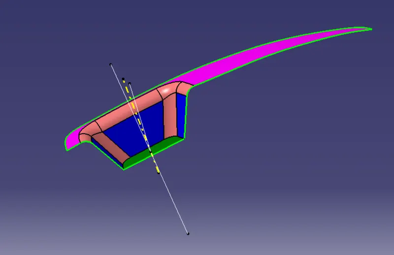
The first step is to ensure that the given surface is a closed surface. This can be fixed by using the join option. For verification use the join tool or the boundary tool. An axis for the tooling direction is decided through visual inspection. The tooling direction in this model will be created paralell to the Z direction. For this a point is inserted in the extrated base surface of the component. An axis system is inserted along this direction. Now 2 sketches are drawn along the ZY plane and ZX plane and the intersections of the class a surface is created. For the sketch along ZY plane the slanting edges in the intersection is extrapolated with 2 lines and a bisecting line is created. For the sketch along the ZX plane the slanting edge of the intersection is extrapolated with the line tool and a new line is drawn passing through the point created. These two lines will be at angle of 4°. A new line will be created which bisects the 2 lines from the sketches created previously. This line represents the tooling axis.
Procedure of draft anaylsis :
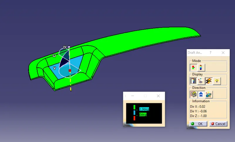
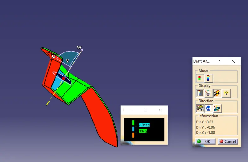
The surface to the analysed is selected and the material options is turned on in the customize option. The feature draft analysis tool is opened. The compass is aligned with the tooling direction. It is made sure that the pulling direction is correct. Otherwise, it is flipped from the open toolbar. The surface is selected to make sure that the draft values are in permissible limits on all faces.
Procedure for creatations of core block, cavity block and parting surface and line for switch bezel :
we used the switch bezel catia file which designed in the earlier challenge so in that we create the new geometric set and named it as core cavity design in that we create various geometric set parting surfaces, core block , cavity block and parting line details discuss in below
parting surface :
in parting surface we required surfaces where act all pressure on it as disscus as above so 1st we create boundary for switch bezel and used this boundary and explor it for 15mm and than get color it this called parting surface with component area as shown in below
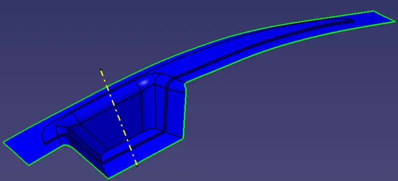
after that we create the parting line we split parting surface with component area to the parting line we get the exact parting surface parting line procedure discuss in below
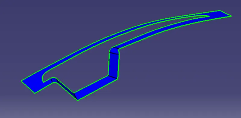
core block :
for core block we sketch the rectangle as shown in below
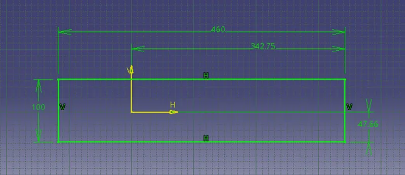
this sketch properly placed on parting surfaces
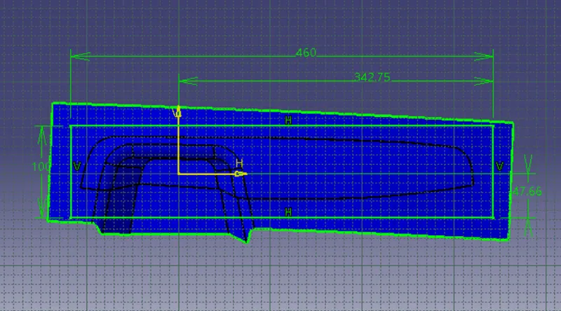
after that we extrude it
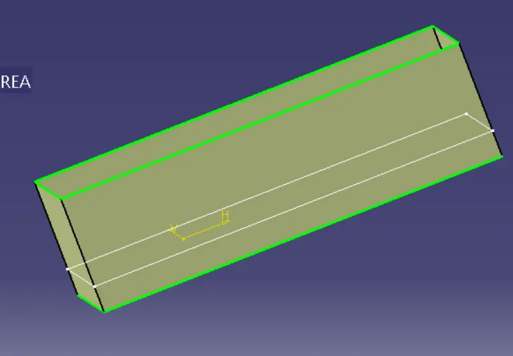
than we trim it with parting surface with component area and get core block and fill the above hollow side and join the fill and trim get the close body than insert body option get new body and named as core blocks used close surface option and close it than get color on blocks
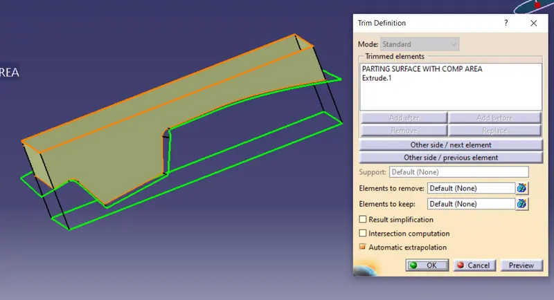
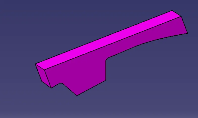
cavity block :
here cavity block also used same sketch which used for core block so we extrude it as shown in below
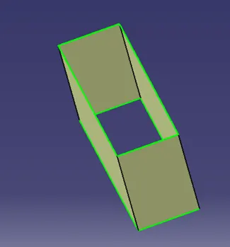
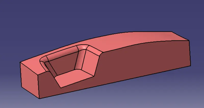
than trim with B surface and get the cavity block we see that in core block we trim bottom portion in cavity block we trim extrude part for above portion with b surface as shown in below figure
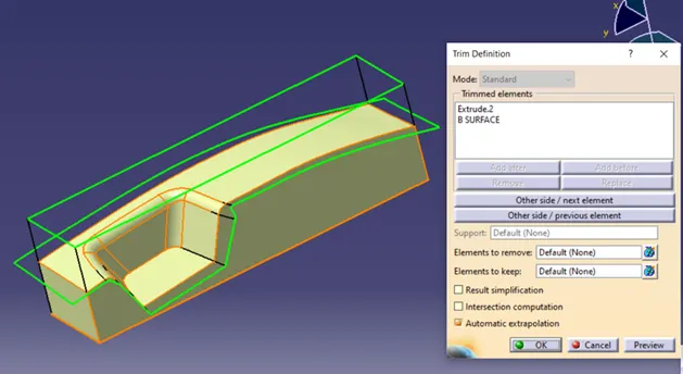
than we used fill command and fill below hollow portion and than join that trim and fill option with join command get close block model as shown below
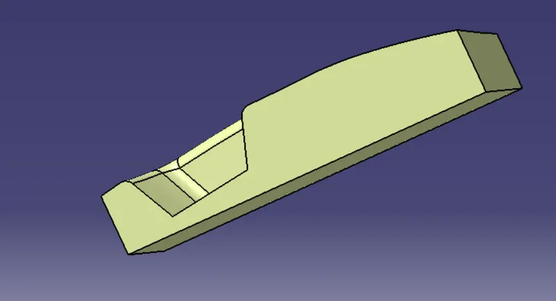
after that we goto part design in mechanical design option than we select the close surface and select thus join which is lastly done and get solid block for cavity before that we inser new body and named it as cavity block
Parting line :
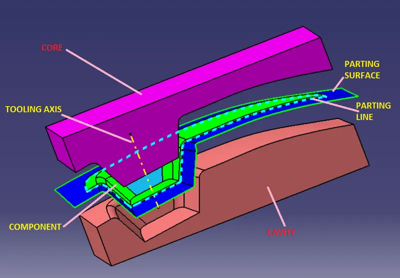
here we create parting line basically parting line is junction of core and cavity and other word line between we meet the core and cavity block knows as parting line so we used intersection command and intersect with b- surface and get the outline we change line type as doted and increase the thickness and clolor it that called parting line
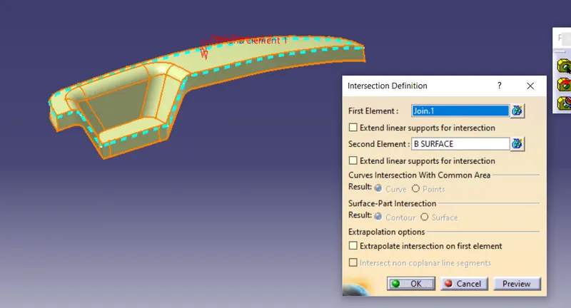
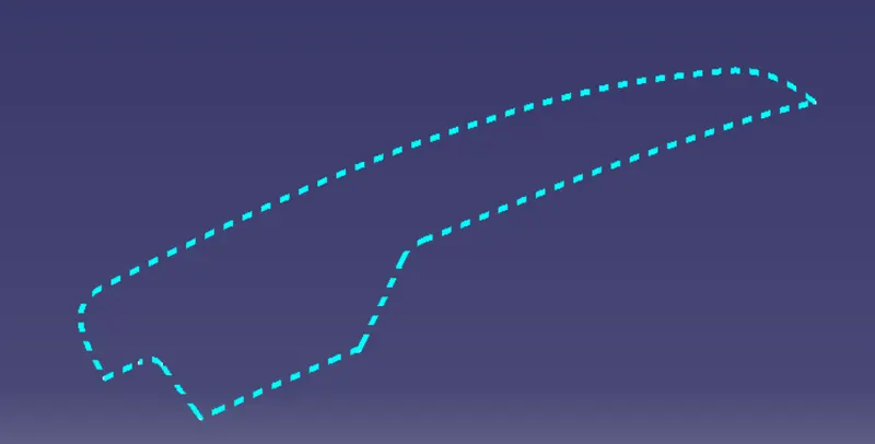
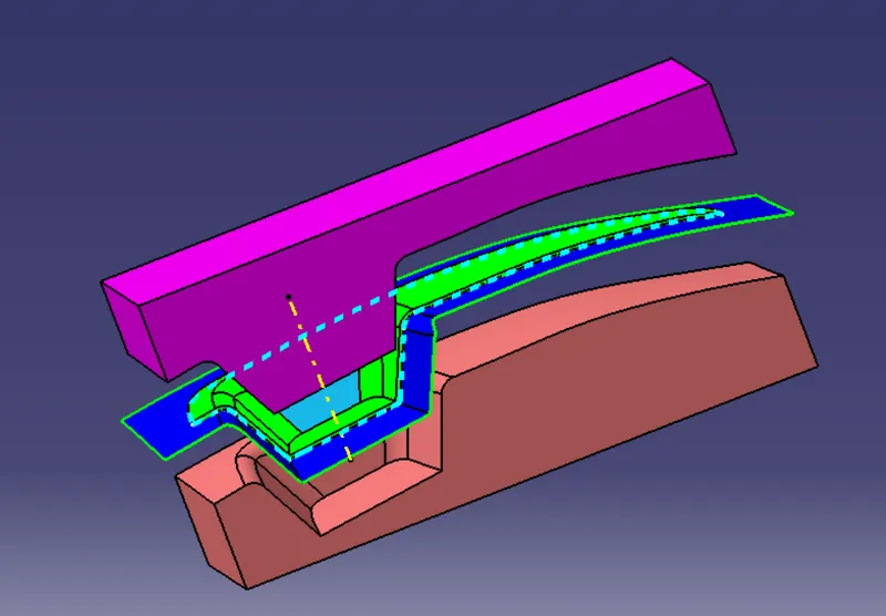
and publish the parting line as well as parting surfaces. and here we used translate command and get gap or seprated the core, cavity and component get exact idea about that
Notes : in this challenges we attched the catia part file in zip format pls refer it .