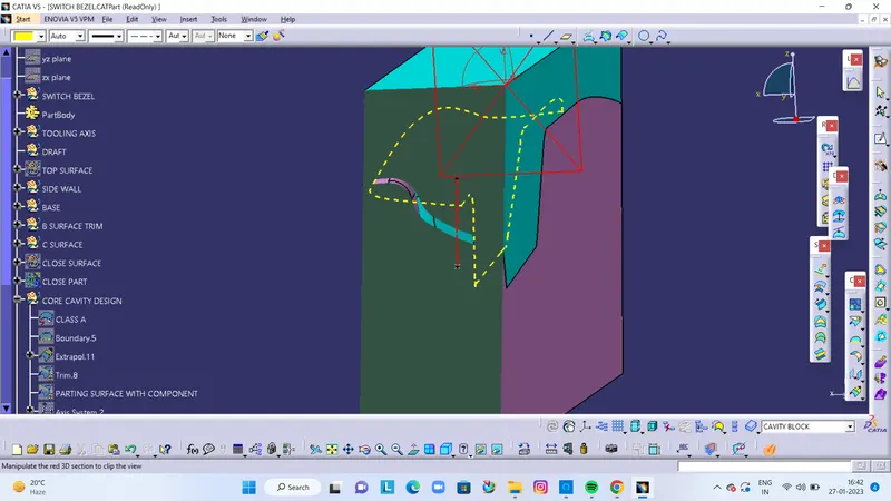
Week 8 - Challenge 6 - Core & Cavity Design
Core & Cavity Design
Aim: To create the Core and cavity blocks for the Switch Bezel Component.
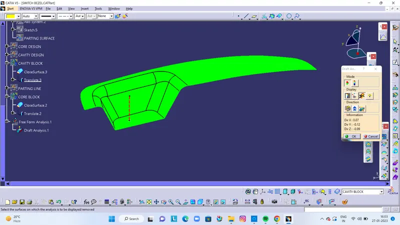
DRAFT ANALYSIS ON SWITCH BEZEL COMPONENT:
- The surface should be green and in the column nominal value 3deg given as input. hence the draft analysis on the switch bezel is successfully performed.
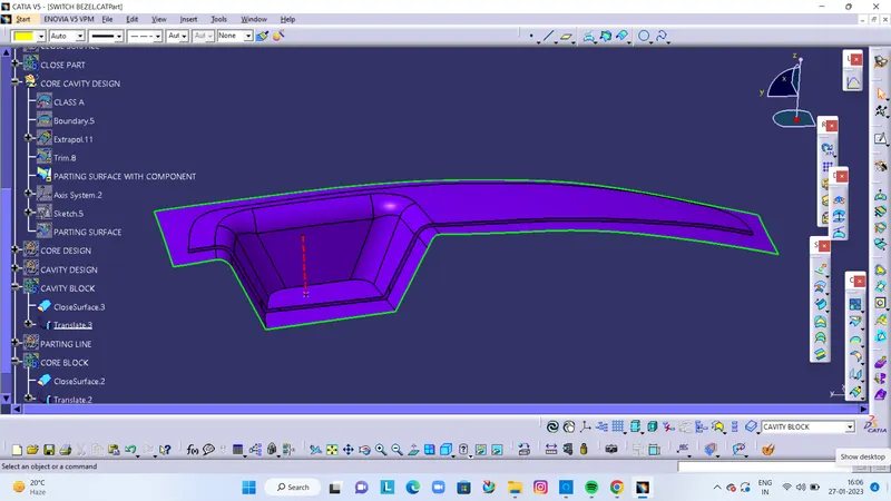
Parting surface:
During the injection molding process, the core and cavity are pressed tightly and form a sealed hollow to avoid the melt flow leakage and maintain certain holding pressure the pressured surface is called a parting surface usually, the parting surface is the most considerable projection outline of the part.
Core:
here, The core block is made by drawing the boundary sketch and extruding it along the tooling axis direction followed by the filling and thickening.
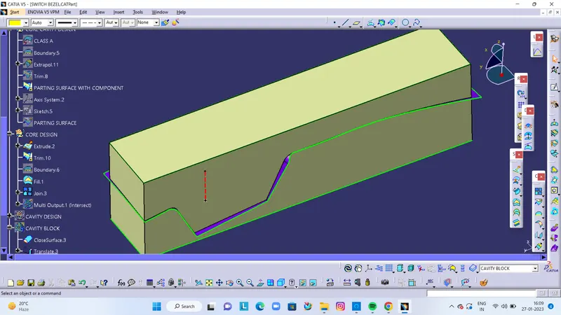
FINAL CORE CLOCK
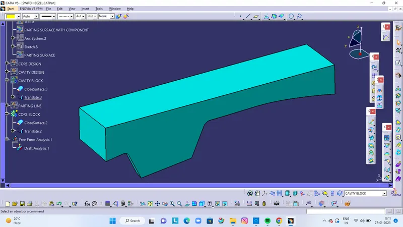
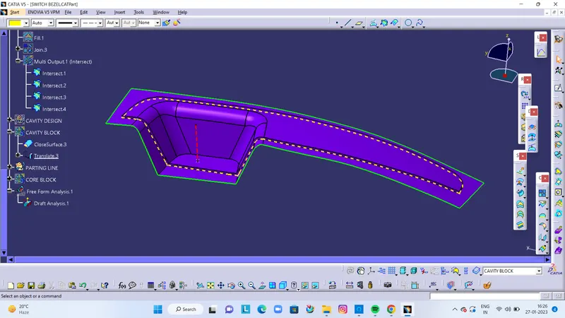
Cavity Design: - To create the cavity block, I trimmed the rectangular extrude with a class B surface to remove the surface which is the upper side of it. After that, I filler the surface which is opened, to make a closed surface by joining both trim and filled surface. Now create a solid body from the closed surface by using the closed surface. The obtained part body from the closed surface is our CAVITY block.
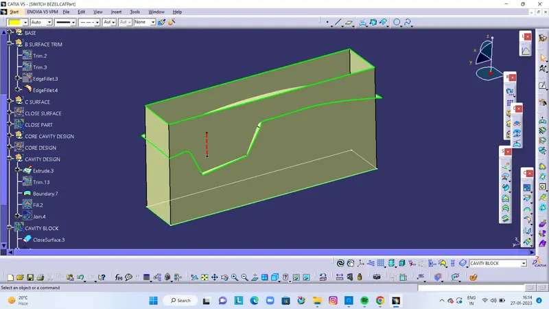
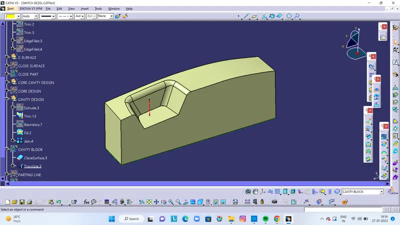
FINAL CAVITY BLOCK
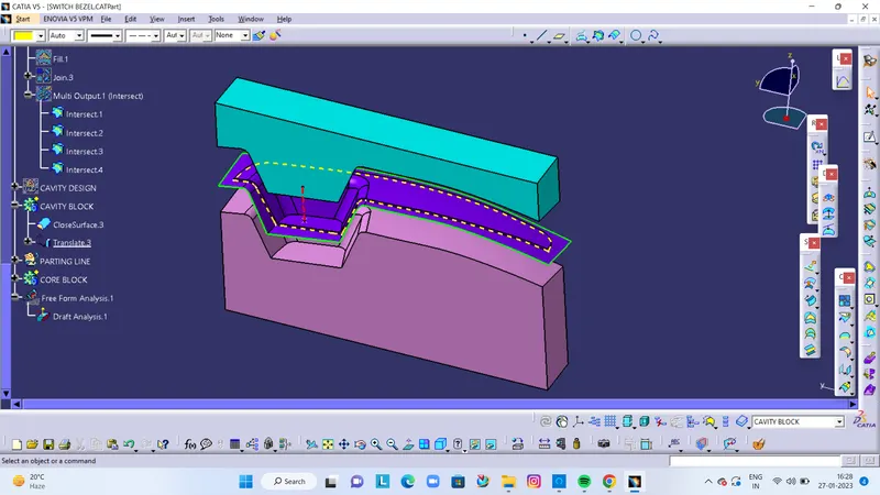
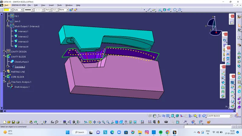
INTERSECTION OF CORE CAVITY DESIGN
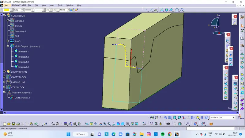
PARTING LINE
- It is the line where the core and cavity intersect each other.
- The parting line lies on the B surface of the Plastic component to protect the A surface from the splash.
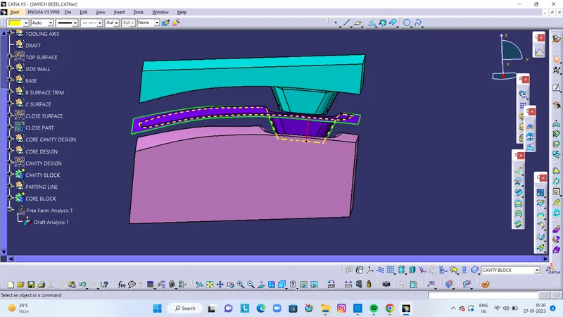
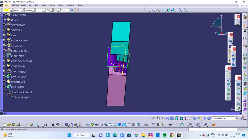
CORE CAVITY DESIGN WITH TRANSLATE