Week 8 - Challenge 6 - Core & Cavity Design
Aim: To design the Core and Cavity of a Switch Bessel. And Draft analysis of a Switch Bessel created using surface commands
Theory: -
Part 1:- Draft Analysis and Tooling Axis.
Draft angle: A draft angle is a slant that is applied to each side of most features of an injection molded part. The angle, which is positioned to run toward the direction of a mold's pull and parting line, helps with releasing the part from the mold.

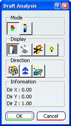
Draft analysis: The Draft Analysis allows the user to easily analyze a part for a proper draft angle. A Draft Angle describes the amount of taper for molded or cast parts perpendicular to the parting line. Find the Draft Analysis in the Tools tab. Draft Analysis is applicable for 3D part models.
Tool Axis Creation: -
In Molding, machine arrangement is given to open the mold along a direction which is known as Tooling Direction.
1. Likewise in our model, we first create a tooling axis from the pocket side walls:-
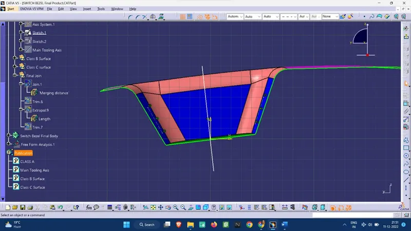
2. Then we create the line from the front walls, and since we do not have a close contour, we take to make a line at an angle greater than the draft angle to provide appropriate inclination.
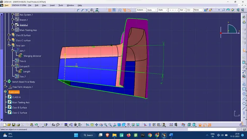
3. Now we create the bisecting line from the two lines we have created as of now.
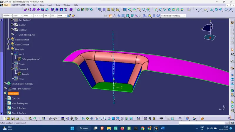
4. To check if this Bisecting Line will actually work as a tooling axis we see the top view of the line to see if all the 3 surfaces in the pocket can be seen or not.
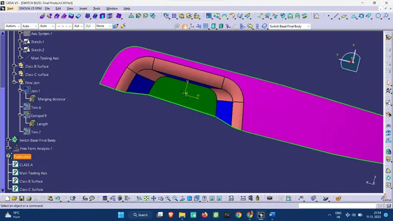
Draft analysis:-
Standard Measurements:
Model Thickness: 2.5 mm
The minimum Draft angle provided: 3 deg angle
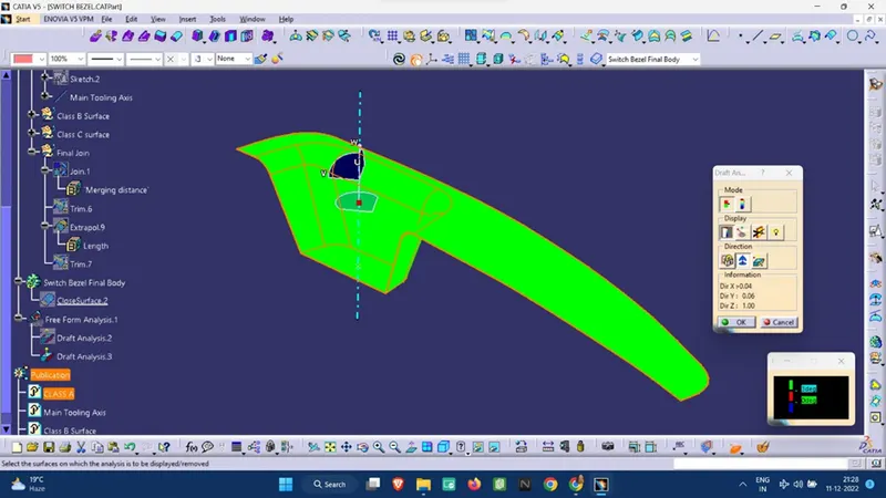
Class A surface Draft analysis:-
Final Body draft analysis:-
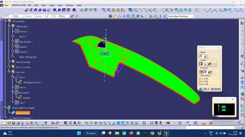
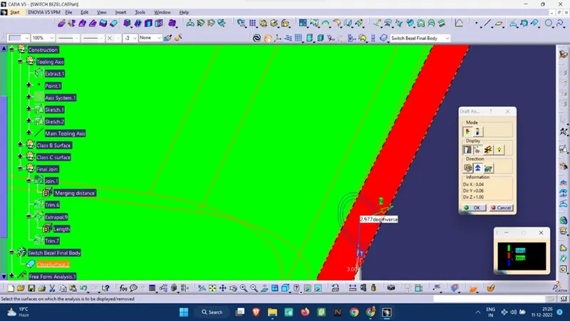
Note: In the first image, the draft angle is taken at 3 deg angle, and at the value of the edge is showing that the draft angle is between 0-3 deg only, as at some points on the C surface despite giving a 3 deg inclination, there is a deviation of only 2.977 deg as shown below, thus in the final image 2.9 deg is taken.
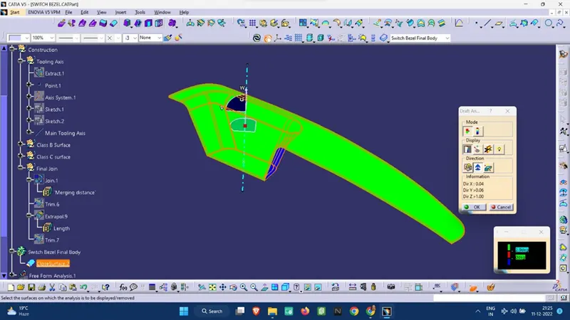
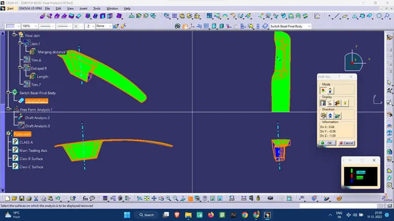
A different view of the draft analysis:-
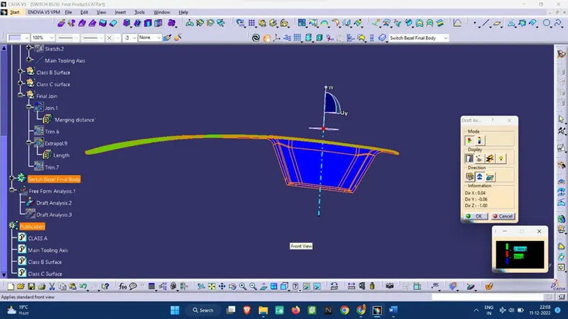
Front View: -
Back View:-
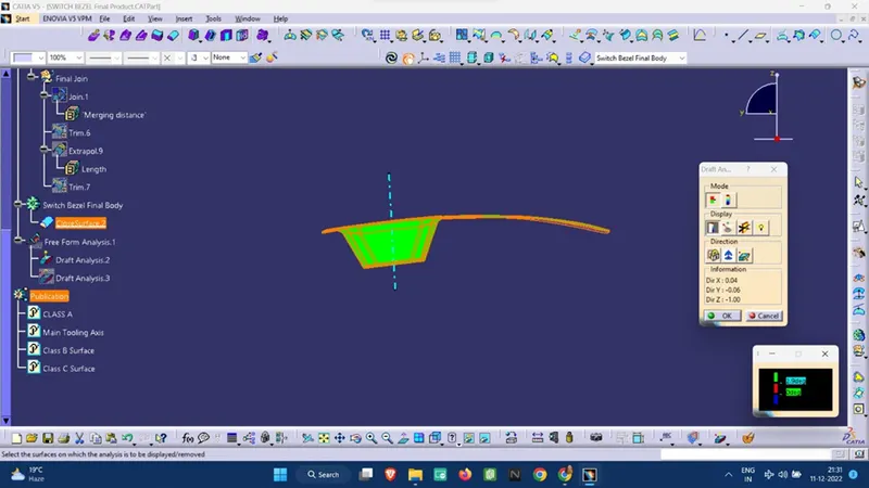
Side View: -
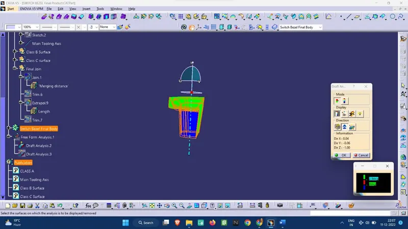
Top view:-
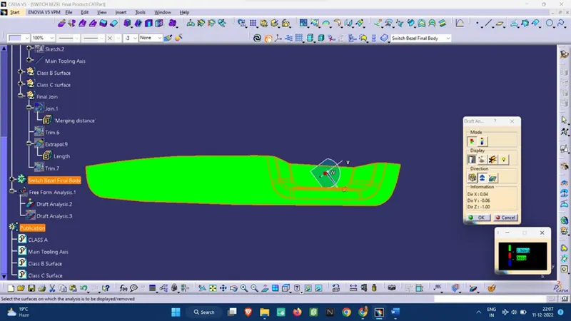
Note:
Green Surface: Denotes that the model satisfies the required draft angle
Blue Surface: Denotes that the model draft angle is below the required draft angle.
Different surfaces:-
Class A surface:
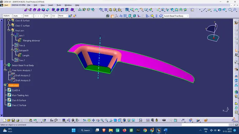
Class B surface:
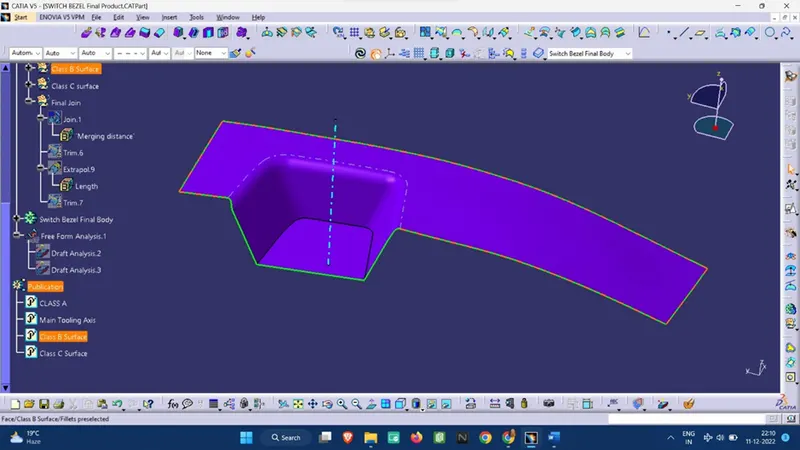
Class C surface:
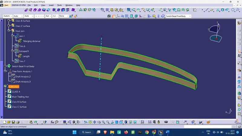
Part 2: - Core and Cavity design.
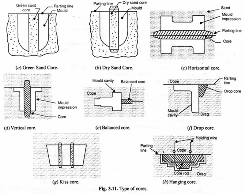
Core: Core is a pre-prepared shape of the mould. It is used to provide internal cavities, recesses, or projections in the casting. It is usually positioned into a mould after the removal of the pattern.
A core is usually made of the best quality sand and is placed into the desired position in the mould cavity. Core prints are added to both sides of the pattern to create impressions that allow the core to be supported and held at both ends.
Cores are subjected to extremely severe conditions, and they must, therefore, possess very high resistance to erosion, exceptionally high strength, good permeability, good refractoriness, and adequate collapsibility.
Types of Core:
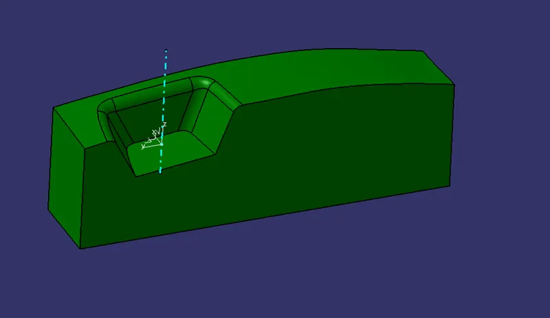
Cavity: It is the recessed part of the mould.
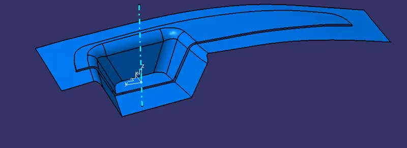
Parting Surface: It is the surface in between the core and cavity and generally on the non-show surface (i.e B surface) which gets pressed during the moulding process.
It is also known as the largest projection of the product.
Parting Line: A parting line, in industrial casting of moulds, is the border line in which draft angles change direction. One can check the parting line in the mould or product which divides the two halves, i.e; the core and the cavity of a moulded part. It is sometimes a starting point for the mould parting surface.
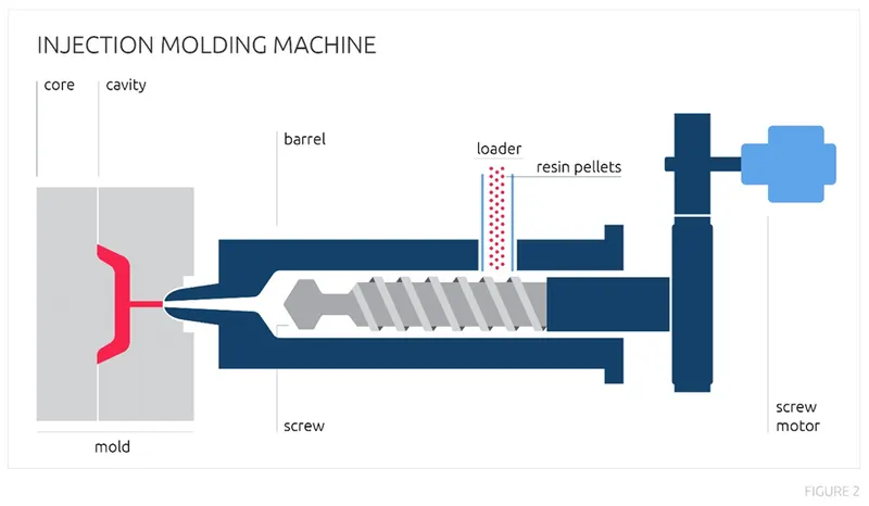
Below is an image showing the process of injection moulding and its parts:-
Design:-
Switch Bessel:-
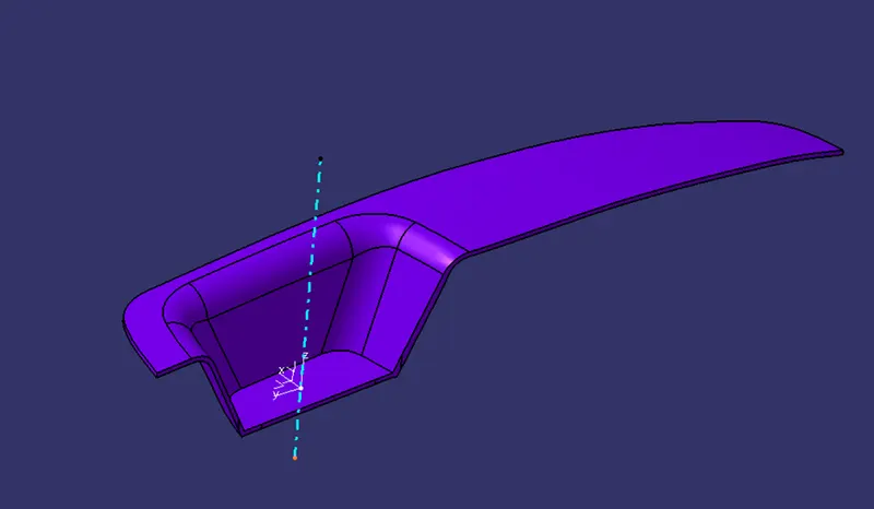
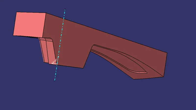
Core:-
Cavity:-
Parting Surface:-
Parting Line:-
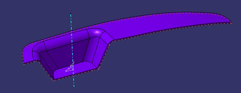
Note: The Parting Line is shown in a Brown dotted line in the above image.
Brief Line representation of the parting surface: -
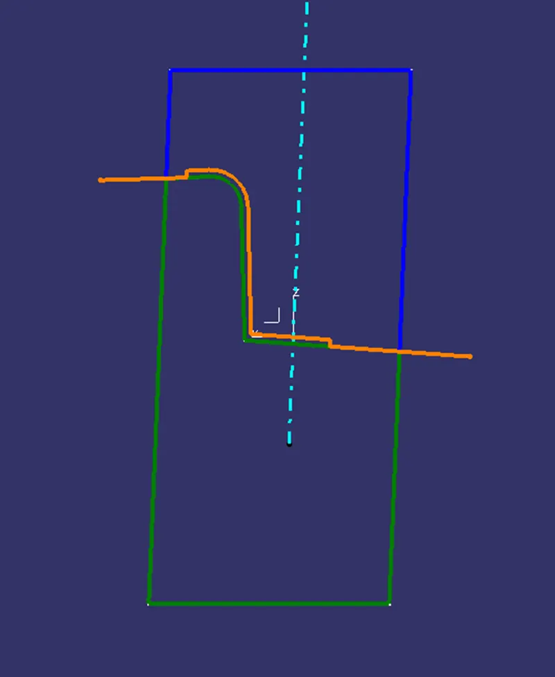
Note: Parting surface is shown with an orange colour line in the above image.
Conclusion:
Draft analysis is a very essential tool for manufacturing a plastic product using Core and cavity manufacturing techniques, hence draft angle should always be provided appropriately.
As the parting surface directly affects the product quality and many defects like flash occurs on the parting surface, one should pay extra caution while designing the core, cavity, and parting surface.