Week 8 - Challenge 6 - Core & Cavity Design
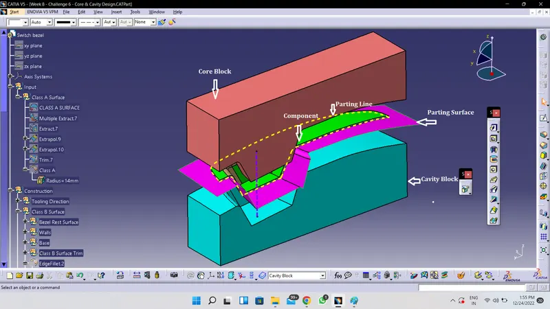
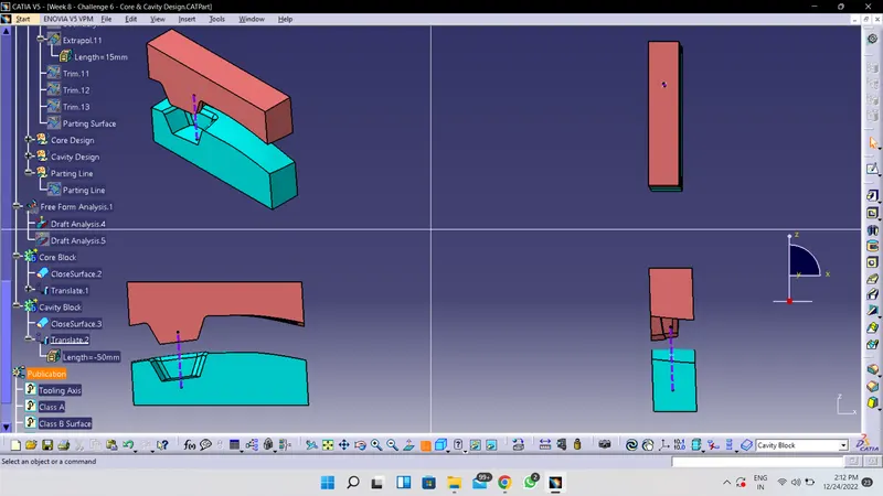
Exploded View Showing -
- Core Block
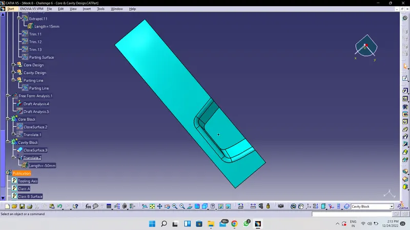
- Cavity Block
- Parting Surface
- Parting Line
- Component
- Tooling Axis
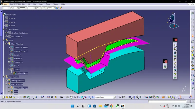
Parting Line & Parting Surface
- Screenshots of the Draft analysis report for both the switch bezel Suface Component
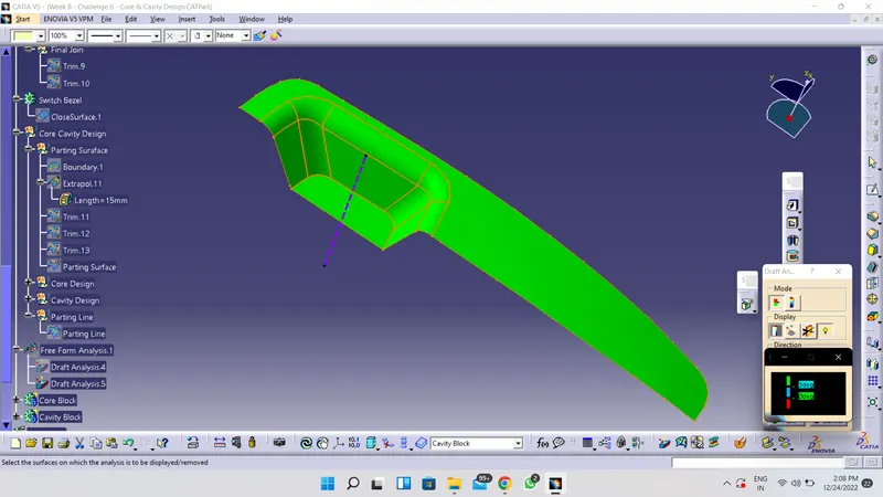
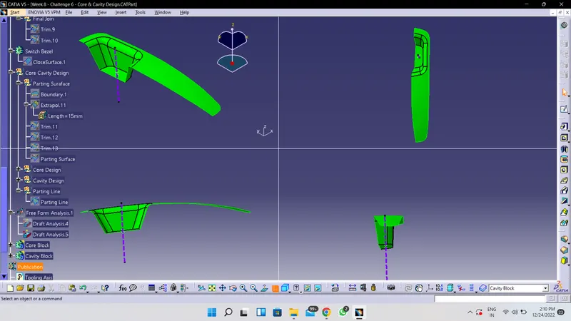
- Screenshots of the Draft analysis report for both the switch bezel Solid component
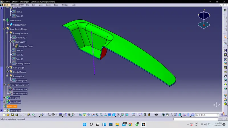
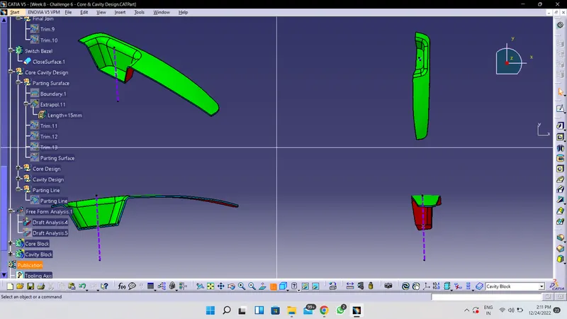
- Screenshots of the core and cavity blocks in various orientations (Isometric, Front, Side, and Top View)
REPORT-
- Initially Ensure the Provided class is good by applying boundry if issues observed then resolve the same before proceeding ahead
- Tooling defines the opening and closing of the core and cavity resulting the formation of mold cavity where the molten plastic is injected and allowed to cool
- To define the tooling axis we initially sppose to check the ease of tooling axis for opening and closing of the core and cavity normal to plane for all 3 planes
- Consider the hole, Ribs, Slots and other Enginnering to check possible Dummy tooling axis
- After the decideing the Dummy tooling axis
-
1 Take intersection for the one plane on Tooling axis 2 Draw line from intersection to check wether intersecting with tooling axis 3 After draw a bisecting line between two lines drwn on intersection 4 Repeated the above steps for the second plane on tooling axis 5 We get 2 Dummy tooling axis from 2 Planes 6 Now as this 2 Dummy tooling axis are not collinear we extracted the tooling axis by bisecting two Dummy tooling axis 7 Obtained Tooling axis is then considererd for Draft Analysis - Use Feature draft analysis by providing pulling direction, surface, draft angle and draft angle direction
- Green results are ok, blue results shown negative draft (for angle use colour scale)
- Once tooling axis is ok procees the B Surface and C Surface by offseting class A Input
- at the end we observe that the walls are not attaing draft angle of 3 deg hence we manage the dummy tooling axis to attain the walls at draft angle 3 degree
- And hence acheive the satisfactory draft analysis reports for the Surface component and Solid Component