Week 8 - Challenge 6 - Core & Cavity Design
REPORT WRITING
CONTENTS
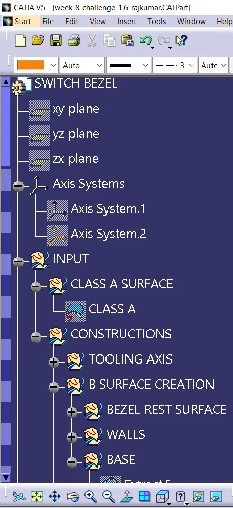
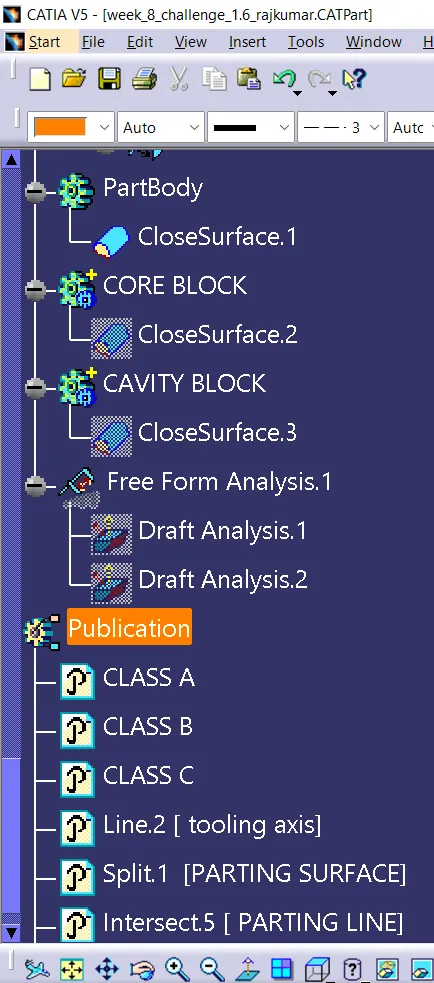
- TOOLING AXIS
- DRAFT ANALYSIS
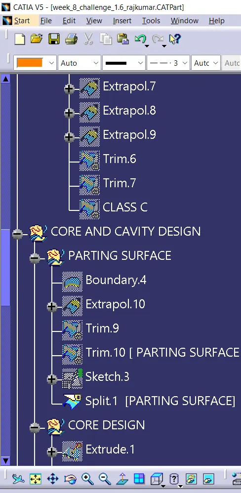
- PARTING SURFACE
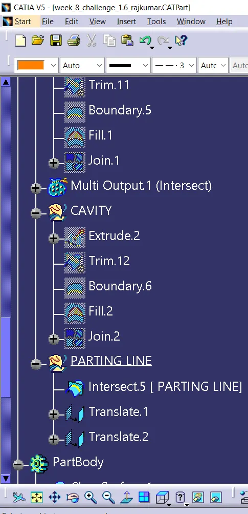
- PARTING LINE
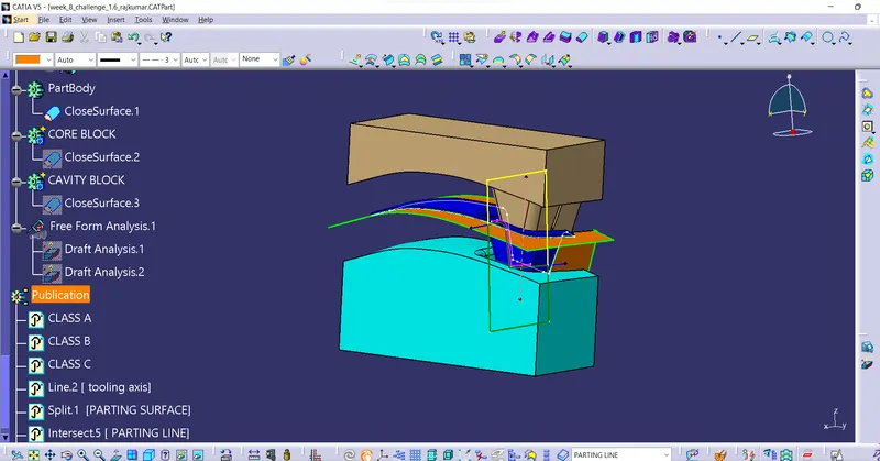
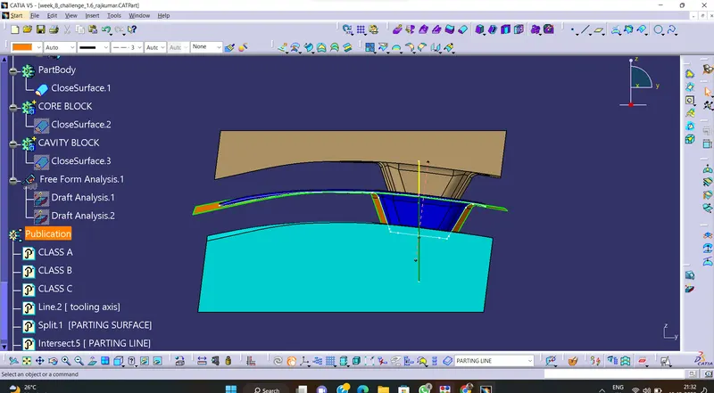
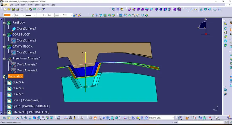
- CORE & CAVITY BLOCK
TOOLING AXIS
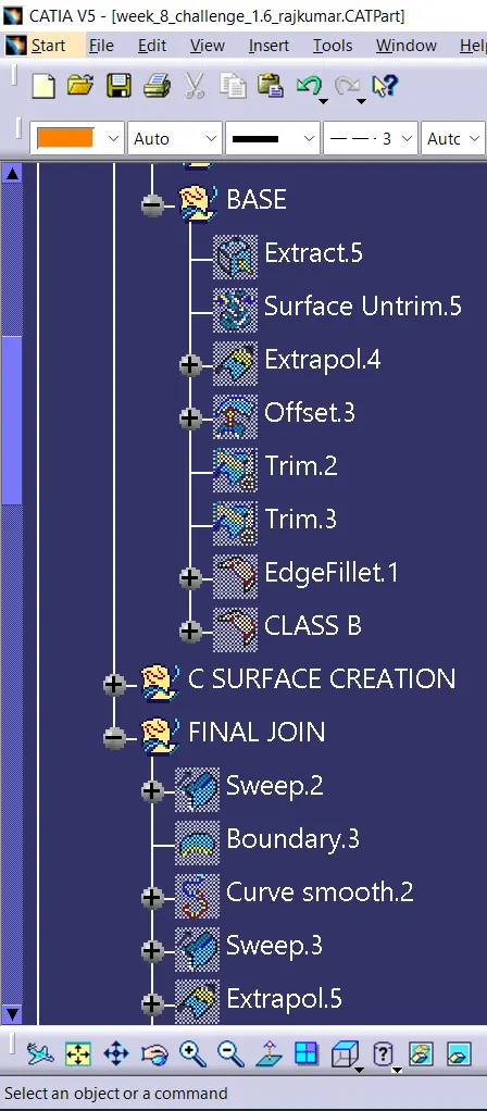
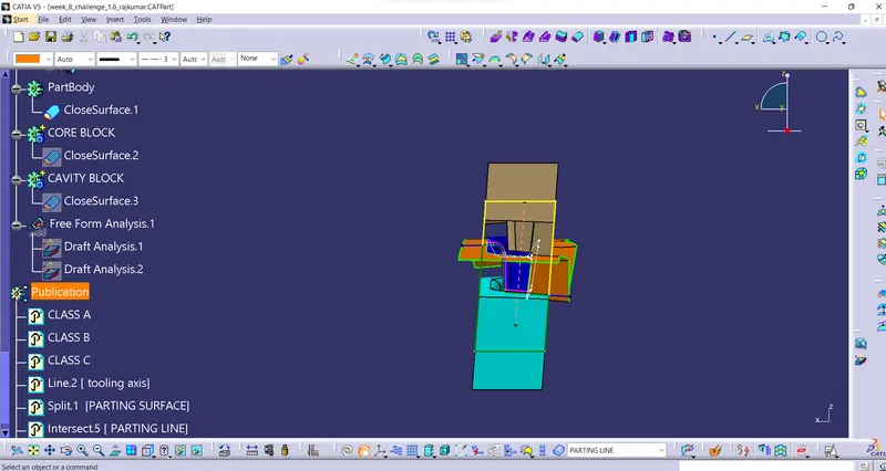
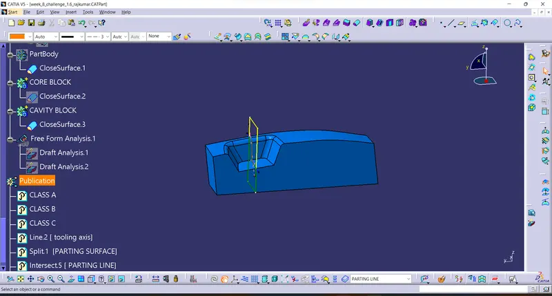
The Tooling Direction is essentially the course that the form pulls a portion. The shape is built in two isolated pieces, fundamentally. You've got a Depression side and you have got the Center side. The Center pulls separated from the Depth and that's the Color line or the Tooling Direction. Open the given CAT part file. Check for crevices between surfaces for that tap on connect and after that preview. If theres any hole between the surfaces connect them with a most extreme resistance of 0.003 mm.Extract the boundary and mask the boundary. Find the proper tooling pivot where the fabric do not meddled with the tooling pivot and all the components can be created. Create an pivot framework utilizing at the middle of the switch Bezel.Intersect the yz plane with regard to the lesson A surface. Hide the class A surface and make point to point lines on the suspected drafts. Create bisecting line with the two lines and point to form a tooling axis. BISECTING LINES were utilized to induce the precise medium from the two sides so that greatest positive draft angle can be achieved.
DRAFT ANALYSIS
The Draft Examination command empowers you to distinguish on the off chance that the portion you drafted will be effortlessly expelled. This sort of examination is performed based on color ranges recognizing zones on the analyzed component where the deviation from the draft heading at any point, compares to indicated values. Before progressing to doggone investigation go to customized see parameter >beneath work >check fabric and after that press ok. Now for draft investigations go to embed » examination » include draft analysis. Use the compasss to characterize the draft direction. In the colour scale alter the draft point to 3 degree. The component changes to green in sign of passing draft angle. Use running point to check the point on the component.
PARTING SURFACE
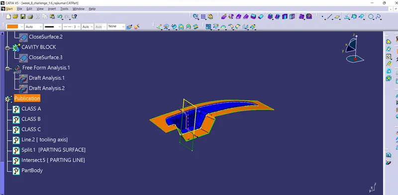
By and large infusion form has two major components : the mobile half and the settled half, amid the injecction molding handle, these two parts are squeezed firmly from a fixed empty to maintain a strategic distance from the dissolve stream spillage and keep up certain holding weight, the squeezed surface are called separating surface , as a rule separating surface are the greatest projection layout of the portion.
PARTING LINE
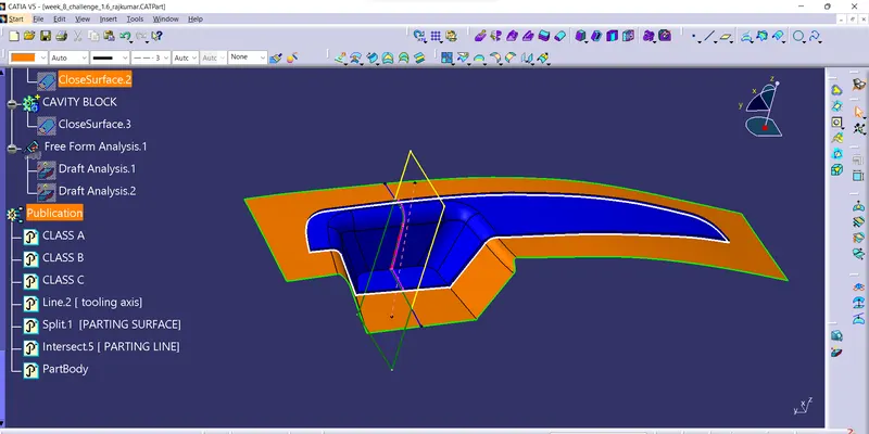
A separating line is an inescapable portion of infusion molded products. It is the line of division between where two parts of a form meet. It shows itself on infusion molded parts as a line that runs the whole border of the part. In most parts, it is fair a line that runs straight down the center.
CORE DESIGN
CAVITY DESIGN
conclusion
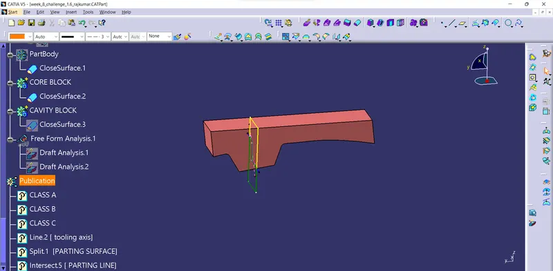
Thus creation of core,cavity,tooling axis,draft,parting line,parting surface has been achieved.