Week 8 - Challenge 6 - Core & Cavity Design
Aim :- The objective of this report is to create the core and cavity block the switch bazel designed.
There are certain step to Design the Core And Cavity :-
- Tooling Axis creation
- Checking Draft analysis for created tooling Axis
- Creating parting Surface
- Creating Core Side
- Creating cavity side.
Tooling Axis creation :-
-
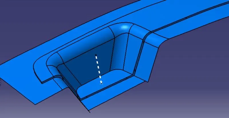
Tooling axis is the axis in which core cavity open during completion of injection molding.
-
To create the tooling axis, we need the proper orientation or view that gives the correct features and draft available in the component.
-
Component view from the Z direction gives the proper view for the tool to see the features present in the geometry.
-
To create the tooling axis from the Z direction we need the tooling axis from the X direction since it gives the draft available at the slanted part.
Draft Analysis :-
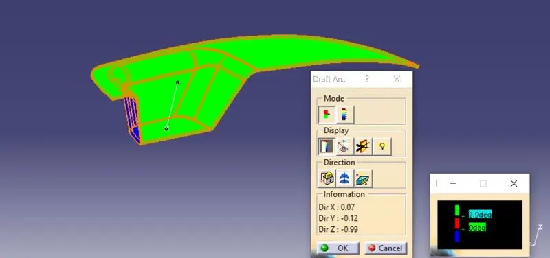
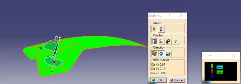
- Draft analysis enables you to detect the part we drafted will be easily removed or Not.
- This type of analysis performed on the base of color ranges identifying the zones on the analyzed element where the deviation from the draft direction at any points, corresponds to specified values.
- This is the Draft Analysis of the Solid Body:-
This is the Draft analysis of the Class A Surface :-
Parting Surface :-
- Generally, injection mold has two major components: the movable halves and fixed halve.
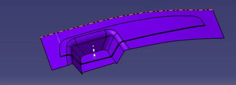
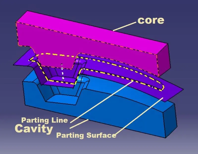
- During injection molding process these halves are pressed tightly from a sealed hollow to avoid the melt flow leakage and maintain certain holding pressure, the pressed surface called as parting surface, usually parting surface is the biggest projection outline surface of the part.
- Parting surface design directly affects the product quality, ease of construction and operation of the injection mold.
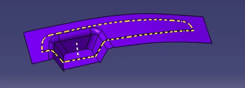
Parting Line :-
- Parting line are where the two halves of the mold meet.
- The Parting Line create a physical line on a part that is both visible and noticeable to the touch.
- These lines however can be hidden or minimized when placed along edges of the part.
- It is represented by dotted line in the below picture.
Core And Cavity Design :-
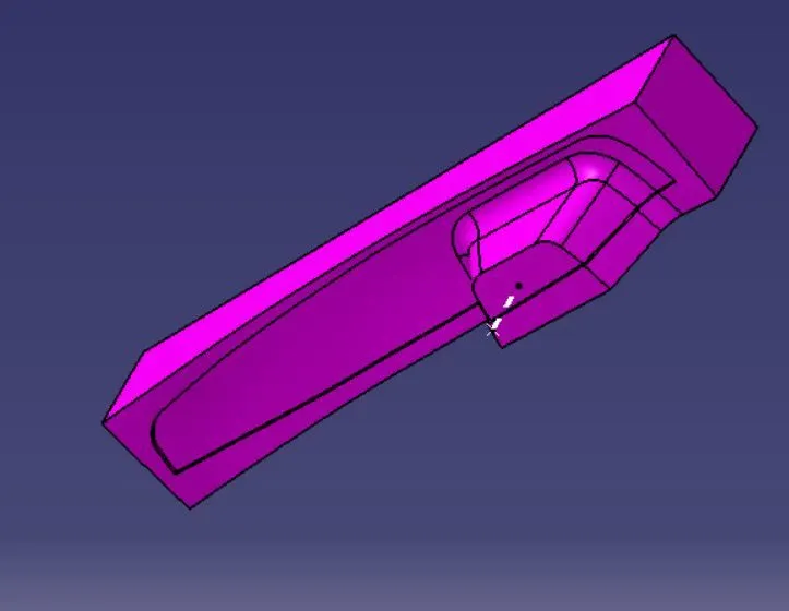
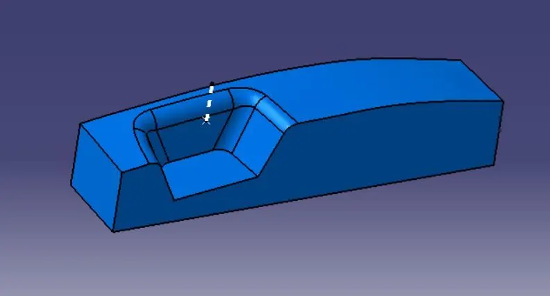
- The Mould Core & Cavity are the shaped sections in either half of the mould tool which give the plastic product its final shape.
- The hot molten material is injected into the core & cavity and then sets hard into shape.
- The design of the core & cavity is essential in the correct formation of the product. The sequence of events during the injection mould of a plastic part is called the injection molding cycle.
- The cycle begins when the mould closes, followed by the injection of the polymer into the mould cavity.
- A core is usually made of the best quality sand and is placed into the desired position in the mould cavity.
- Core prints are added to both sides of the pattern to create impressions that allow the core to be supported and held at both ends.
Core:-
Cavity :-
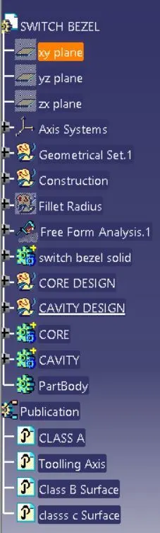
Tree Structure :-
Conclusion :-
Finally we Design the Core and Cavity Part of the Switch bezel as per the Design Criteria.