Week 8 - Challenge 6 - Core & Cavity Design
Aim: To create a switch bezel from the given Class A surface and to create core and the cavity block.
Switch Bezel
A switch bezel panel is nothing but a part which consists of the switch panels for the power windows and also has some place to rest the passenger’s hand on it. It is assembled on the main door trim panels.
Class A Surface: Surface made by the designer which is given as the input to work on it. It is an asthethic surface.
Class B Surface: Class B surface is created in a certain distance according to the thickness of the part. Class B surface contain all the engineering components.
Class C Surface: Class C surface joins Class A surface and Class B surface.
Class A Surface
- Firstly, the 3D CAD file of the Class A Surface is downloaded.
- Next step is to check the continuity of the Class A Surface. This is to ensure that there is no gap in between surfaces.
- Firstly, visually inspect the Class A surface and then apply the Boundary or Join command on the Class A surface to make sure there is no gap in between the surfaces.
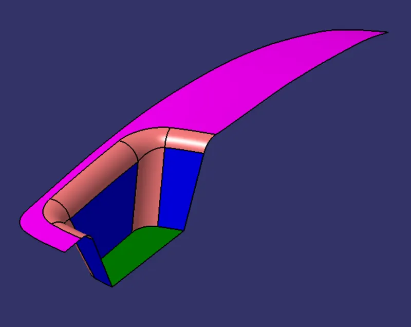
Figure: Class A Surface
Tooling Axis:
- Tooling axis represents the opening and closing of the mold core and cavity during the manufacturing of the components. A plastic product designer should consider the best tooling direction to cutdown the cost of the component very less.
- Firstly, check visually for the best possible tooling axis and we find from the Z-direction it is most convenient.
- The base surface of the Class A Surface is extracted and a point at the centre is created and an Axis system is inserted to the point.
- Using Project intersection along the YZ plane is created and then two inclined lines are drawn inside the sketch and then bisecting line is created from the two inclined lines as the reference.
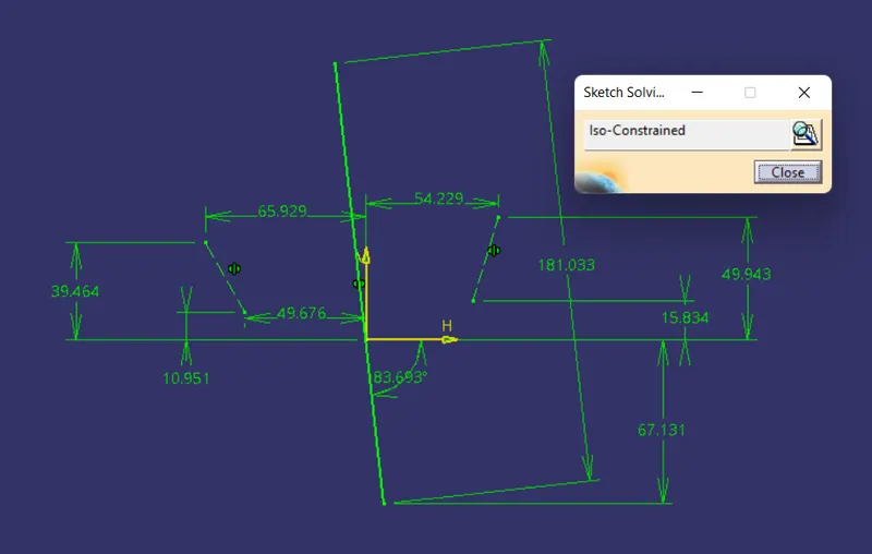
Figure: Sketch on YZ plane
- Same procedure is followed on the ZX plane but as one side inclined line is not present so a line is extruded from the centre point along Z-direction and an angle of 6⁰ is provided.
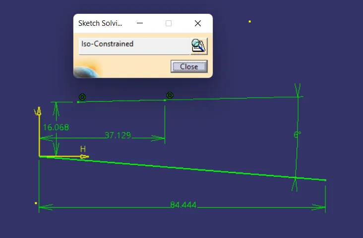
Figure: Sketch on ZX plane
- From the lines of the above sketch as the reference, the bisecting line is created and named as “Tooling Axis”.
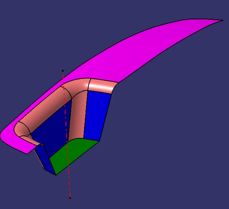
Figure: Tooling Axis on the Class A surface
Draft Analysis on Class A Surface:
- The Draft Analysis allows the user to easily analyses the proper draft angle and manufacturability of the designed component.Draft analysis is done after determining the tooling axis, draft analysis is used to check whether the minimum draft (3 degrees) is maintained or not.
- Firstly change the viewmode of the component in the customized parameter mode and apply the Draft Analysis Command on the Class A surface
- Then drag and align the compass on the tooling axis and lock the compass
- Perform the draft analysis by clicking on the component
- The green colour shows the positive draft tooling direction and the given surface passes the draft analysis.
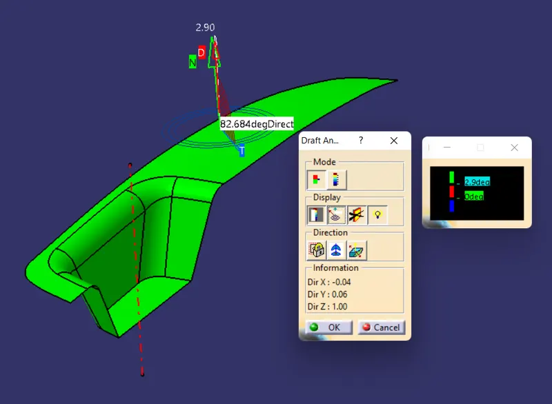
Figure: Draft Analysis on Class A Surface
Class B Surface:
- The required surfaces of the Class A are extracted and then Untrim operation is performed on them.
- Further surfaces are exptrapolated and required trim operation are performed on it.
- As the required thickness is of 2.5mm then the surfaces are offseet to 2.5mm
- Reuired Corners are provided with the fillet of 12.5mm
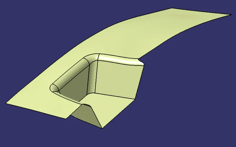
Figure: Class B surface
Class C Surface:
- Outer Edges of the Class A surface are extracted using Multiple extract command and to avoid the patches teh curve is smoothened using Curve Smooth option.
- Using Sweep Command then the surfaces are created and then they are extrapolated
- Required portion of the C- surface are trimmed out.
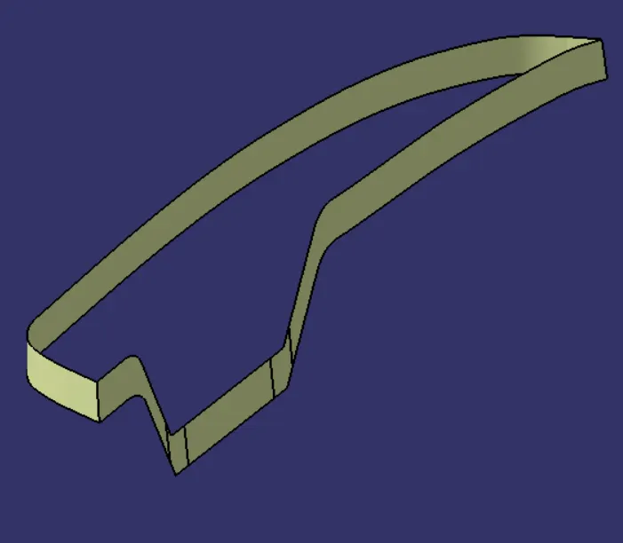
Figure: Class C Surface
Final Closed Surface:
- Further, Apply the Join command on the Class A Surface and the Class C Surface

Figure: Class A+C Surface
- In next step, we apply Trim operation between the Class A+C Surface and the Class B Surface and thus we finally get Final Closed Surface
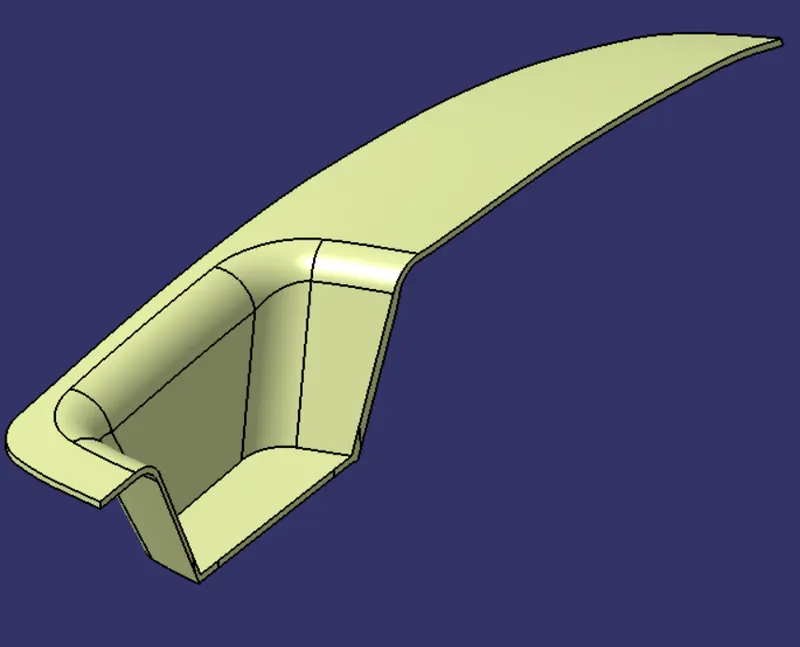
Figure: Final Closed Surface
- Next switch to the Part workbench and apply the Closed Surface command on the Final Closed Surface
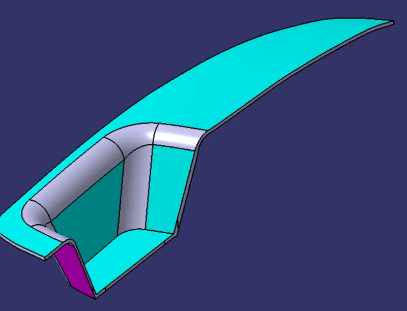
Figure: Final Closed Surface partbody
Draft Analysis on the Final Closed Surface Partbody:
- Follow the same procedure as done on the draft analysis of the Class A surface.
- Change the view mode of the component in the customized parameter mode and apply the Draft analysis command on the Class A surface.
- Next drag and align the compass on the tooling axis and lock the compass on the tooling axis.
- Perform the draft analysis by clicking on the component.
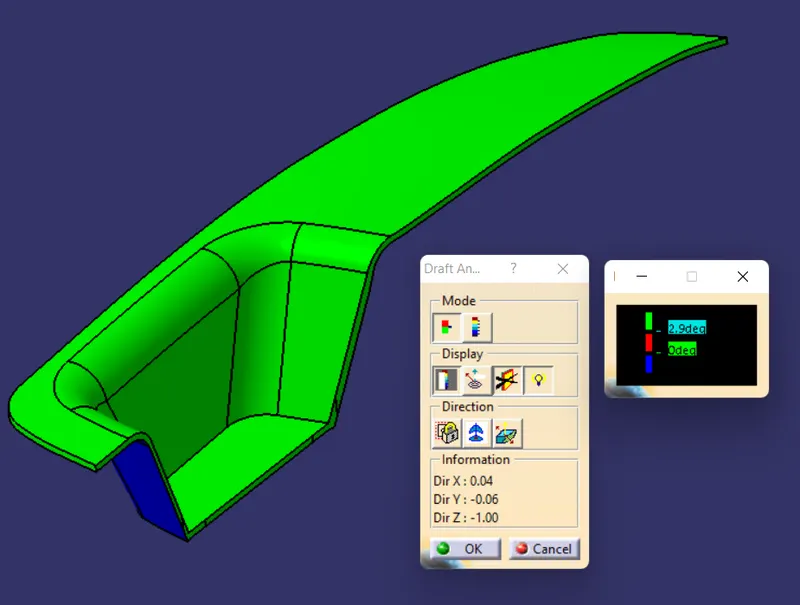
Figure: Draft analysis on Final Closed Partbody
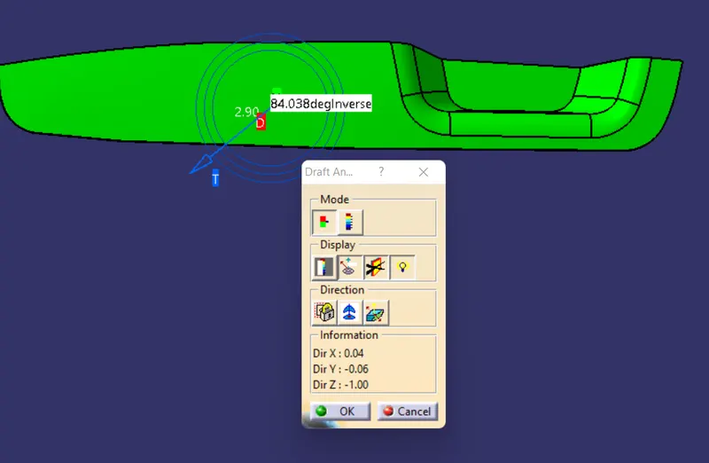
Figure: Draft analysis on the Partbody in Top-view
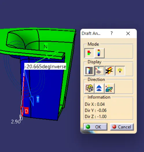
Figure: Side View of Draft analysis on Switch Bezel partbody
Core and Cavity design
The Mould Core & Cavity are the shaped sections in either half of the mould tool which give the plastic product its final shape. The hot molten material is injected into the core & cavity and then sets hard into shape. The design of the core & cavity is essential in the correct formation of the product.
Core Block Design:
- Create a boundary on the Class A Surface and using the Extrapolate Command and taking the Class A Surface and its boundary as the reference extrapolate it.
- Using the Trim Command, trim the extrapolated surface and the Class C surface and further then trim with the Class B surface.
- Create a rectangular sketch on the trimmed surface such that it must not be outside the trimmed surface
- Next extrude the rectangular sketch along the tooling axis and trim it with the other surface.
- Using the Fill command, close the extruded surface open upper end.
- Finally using the Join command join the fill and the extruded surface and thus finally the core block surface is created.
- Switch to the Part Workbench, apply the Closed Surface command on the Core block surface.
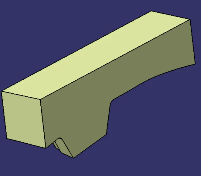
Figure: Core Block Surface
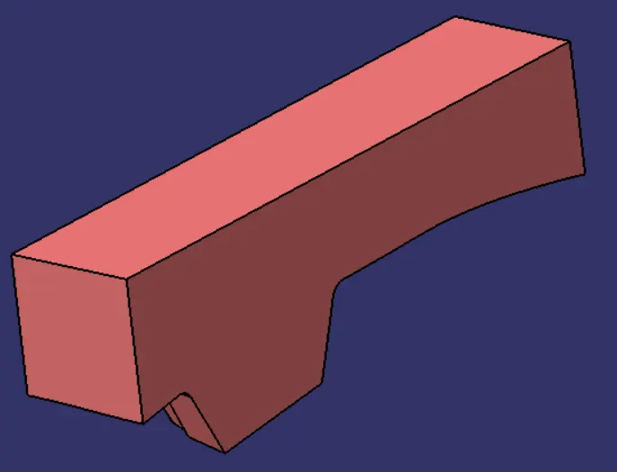
Figure: Core Block Closed Partbody
Cavity Block Design:
- Same procedure is followed as in the Core Block design
- Extrude the rectangular sketch with reference to the tooling axis direction
- Apply the Trim operation between the extruded surface and the Class B surface
- Using the Fill Command, fill the lower open end of the surface
- Finally apply the Join operation between the Fill surface and the trim surface. Hence, Cavity block surface is created.
- Switch to the Part workbench and apply the Closed surface command on the Cavity block surface to create the partbody.
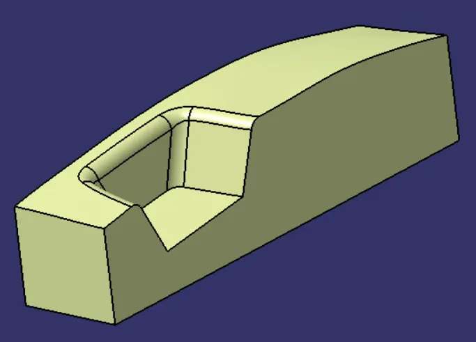
Figure: Cavity Block Surface
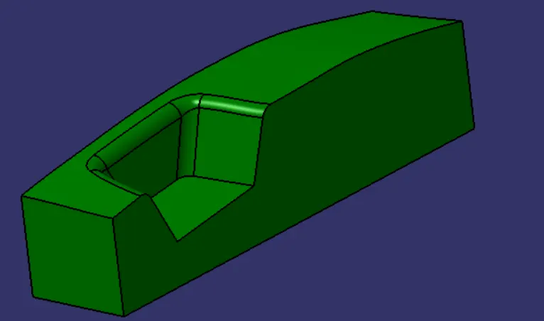
Figure: Cavity Block Partbody
Parting Line:
It is the junction between component and parting surface. Parting line should always lie on the B surface of the component.
- Parting line is created by applying the Intersect Definition Command by selecting the B-surface as First element and the A+C Surface as the second element.
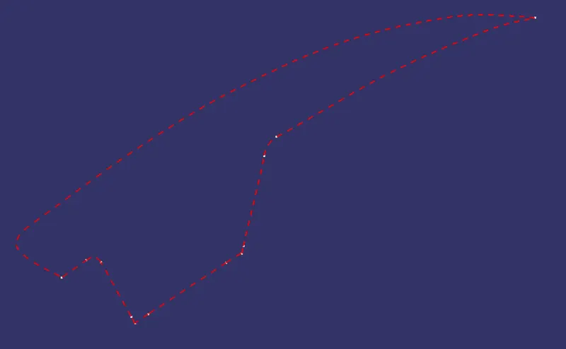
Figure: Parting Line
Parting Surface:
During the injection molding process, the core and cavity blocks are pressed tightly and form a sealed hollow mold cavity, the pressed surface is called the parting surface. Parting Surface are the biggest projection outline of the Part
- Produce the Surface by applying the Trim operation between the Extrapolated surface of the Class A surface, Class C surface and further trim with the Class B surface.
- This surface is named as the " Parting surface with Component area ".
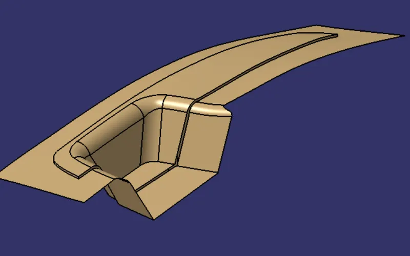
Figure: Parting Surface with the Component area
- Further apply the Split command by selecting the above surface as the Element to cut and the parting line as the cutting element.
- Thus Parting Surface is created.
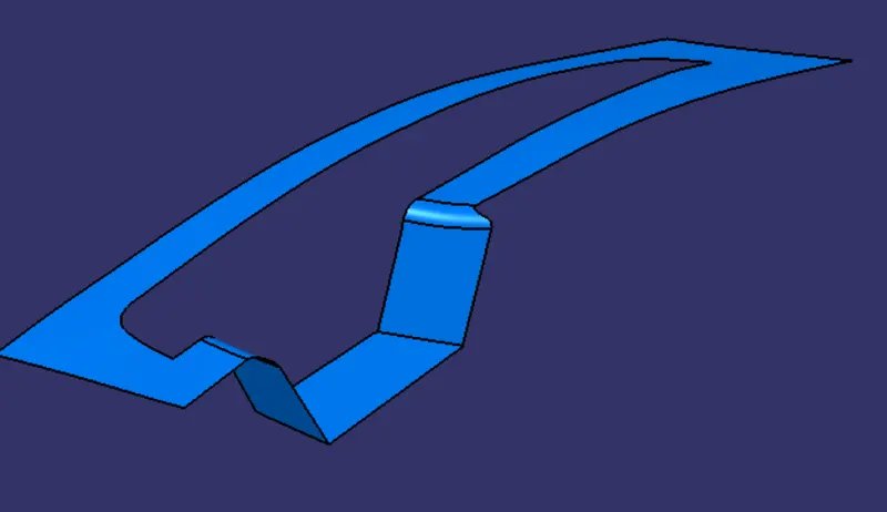
Figure: Actual Parting Surface
Translation is provided on the Core Block and the Cavity Block for the proper representaion.
Differnet Views of Core Block, Cavity Block, Parting Surface, Parting line and Class A Surface:
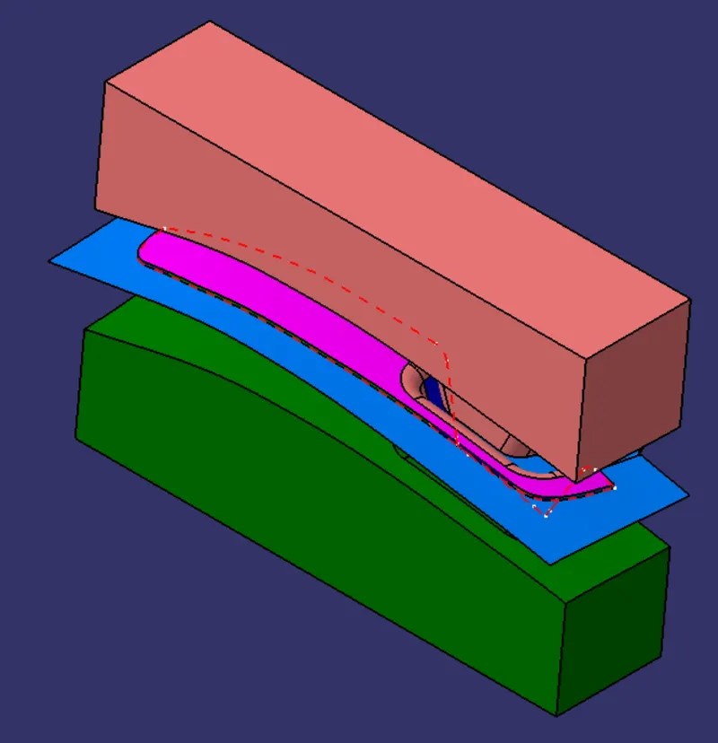
Figure: Isometric View
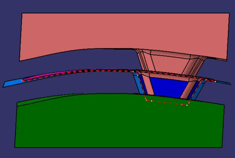
Figure: Front View
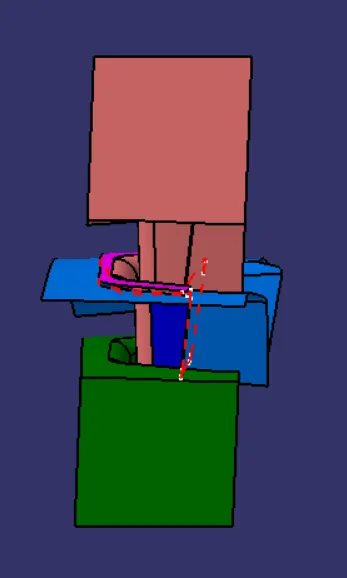
Figure: Side View
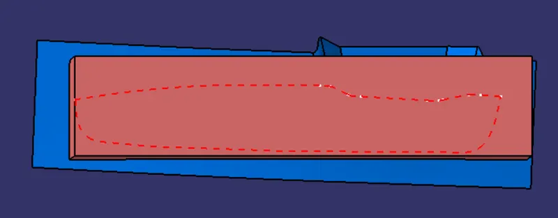
Figure: Top View
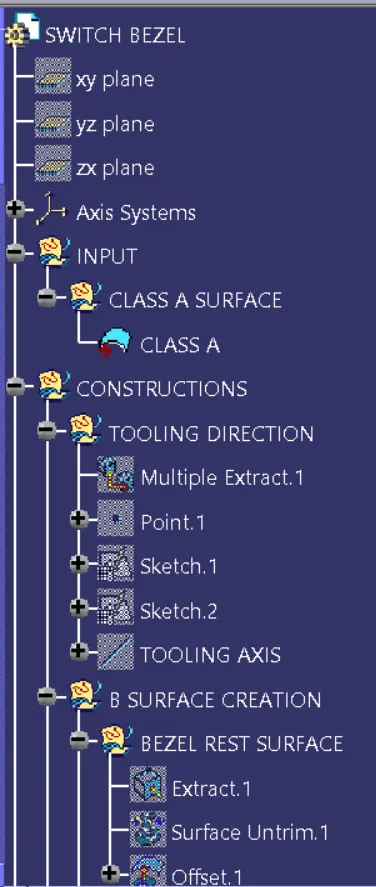
Figure: Expanded Tree(1)
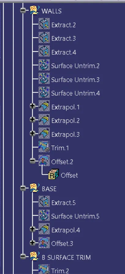
Figure: Expanded Tree (2)
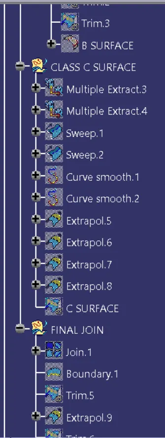
Figure: Expanded Tree (3)
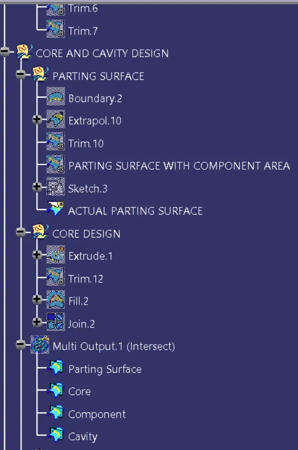
Figure: Expanded Tree (4)
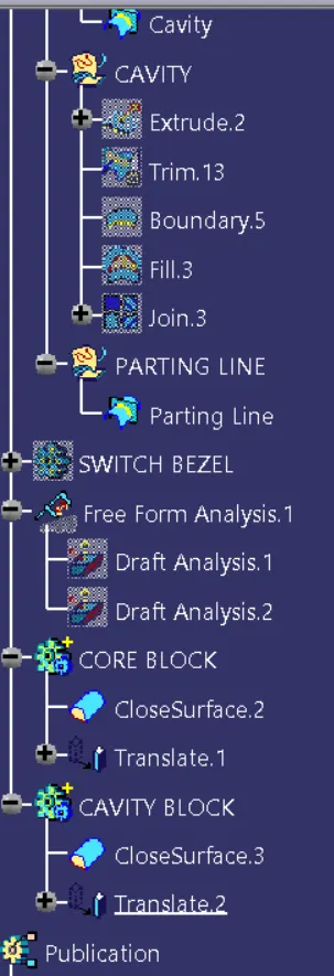
Figure: Expanded Tree (5)
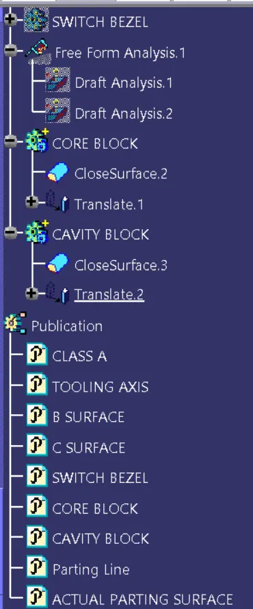
Figure: Expanded Tree (6)