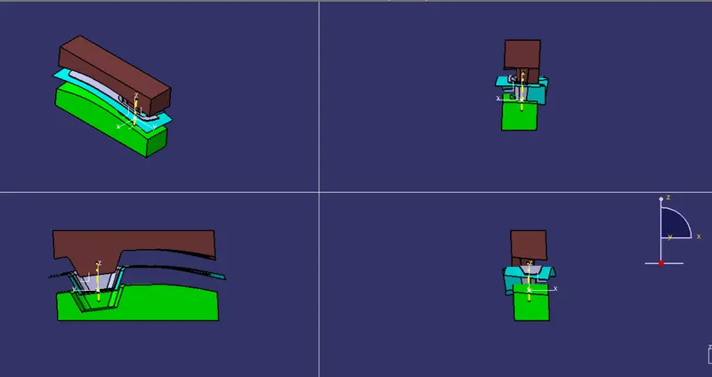
Week 8 - Challenge 6 - Core & Cavity Design
Core and Cavity Design of Switch Bezel
Aim : To Create core and cavity block for the Switch Bezel Component.
To start with is to download and open the below class A file of the switch bezel.
Now check the continuity of the surfaces using bounddary option. There should not be not gao between the surfaces.
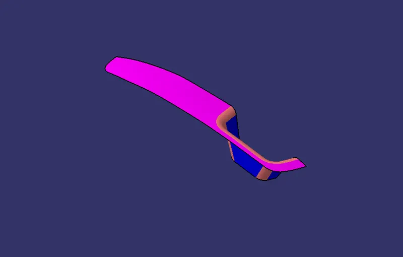
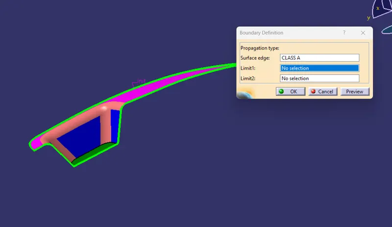
1) Tooling Axis / Direction creation:
Once it is verified that there is no gap, next step is to create Tooling axis of the above model. Check visually for the direction of tooling. The should be permissible 3 degree draft angle for the ejection of the part after manufacturing.
For that should create a dummy axis in any direction, here in Z direction.
The base of the class A surface is extracted and a point at the center is created and axis system is inserted.
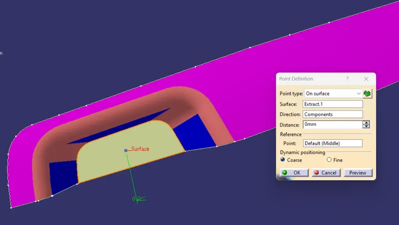
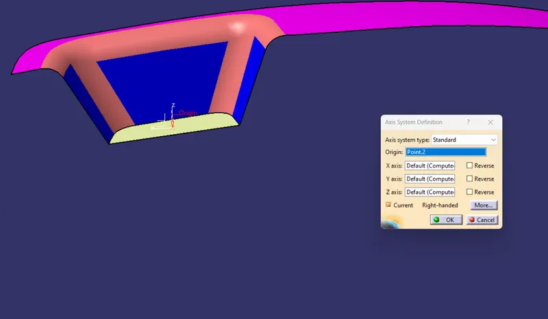
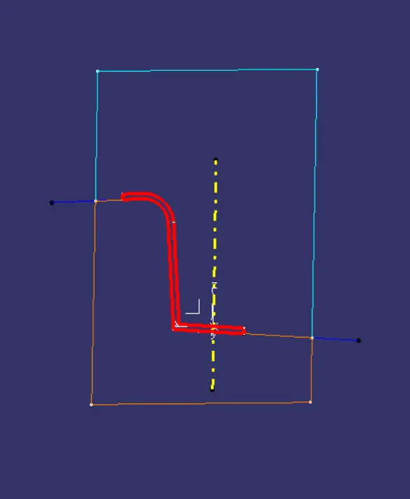
Now create a sketch using created axis and point. Create the intersection of the class A surface on the plane as below.
Create 2 line as shown and using bisect option Create a bisecting line between the 2 new lines.
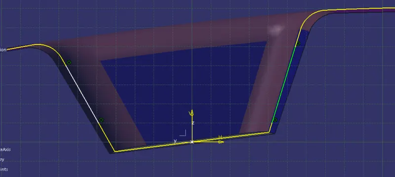
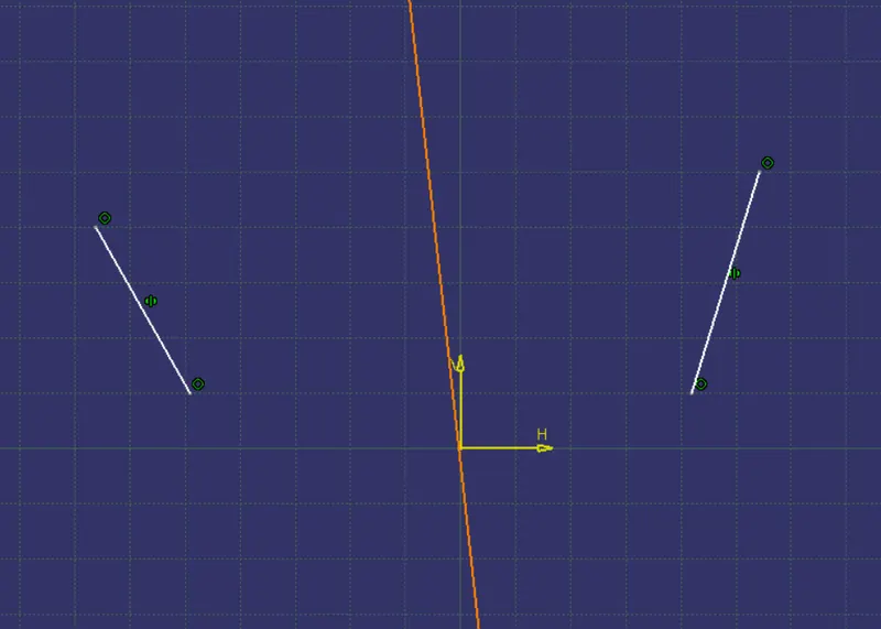
Similarly create a bisecting line in a x direction on zx plane. As we know that the draft anlge should be 3 degrees the line from the origin point is created and the angle is given 3 degree from the class a surface.
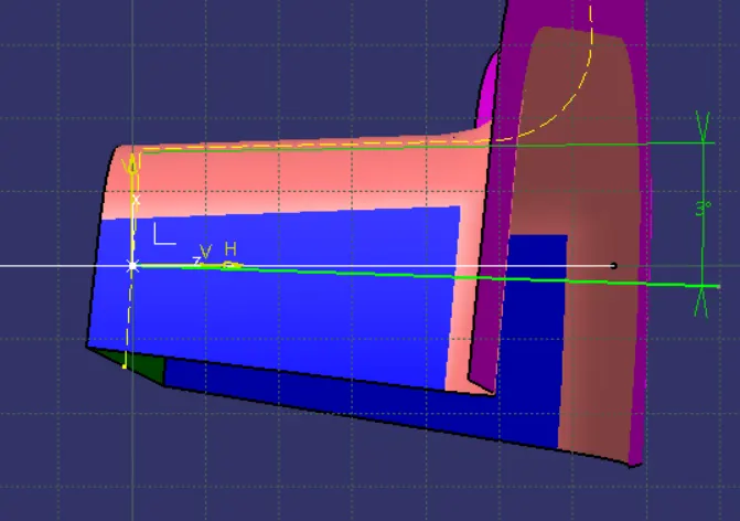
Create a common bisecting line with the halp of two lines created to obtion a tooling axis.
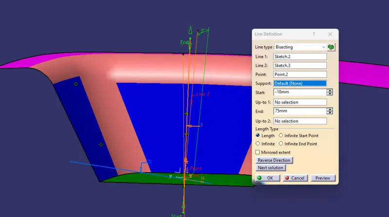
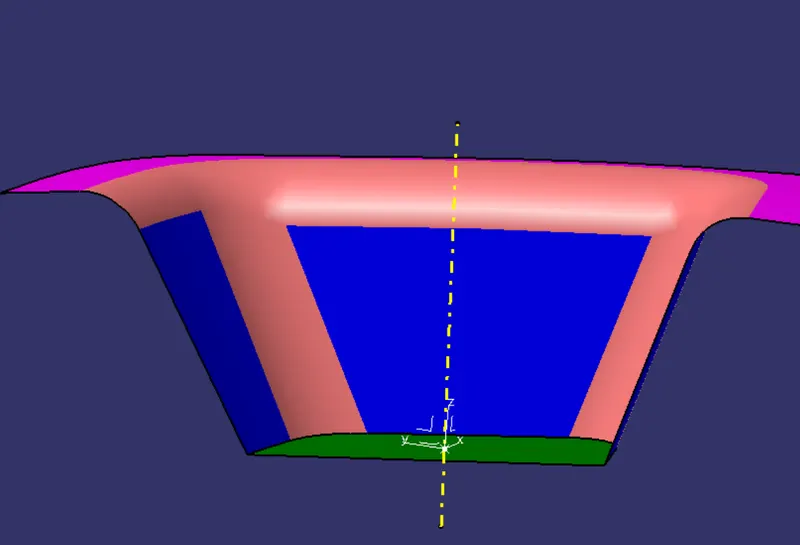
As the tooling axis is created next publish it using publication option in tools section.
2) Draft Analysis:
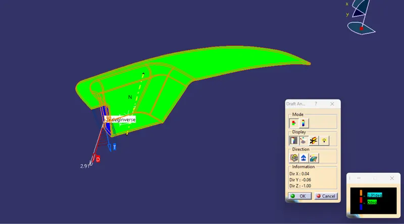
Change the view mode to the custom view and select view paramater as Material mode, then the draft analysis is enalbles.
Click the draft analysis option  , move the compass with the red dot to align with the tool axis.
Now lock the compass and click anywhere on the part, the color will be changed.
Change the value of the green color limit as 3 degrees.
The green color shows that the surface satisfies the draft angle and other color if the angle is not satisfied. This can be corrected by altering the angle and measuring at points to get succesfully draft to get satisfied.
3) Parting Surface Design:
Generally injection mold has two major components: the movable half and the fixed half, during the injecction molding process, these two halves are pressed tightly from a sealed hollow to avoid the melt flow leakage and maintain certain holding pressure, the pressed surface are called parting surface, usually parting surface are the biggest projection outline of the part..
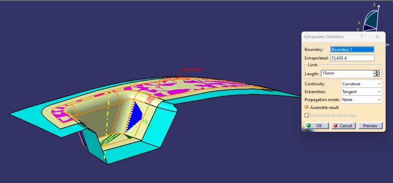
Create the boundary of the class A and extrapolate it.
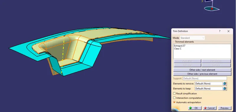
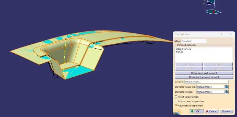
Then trim the surface with the class C surface and finally with class B surface.
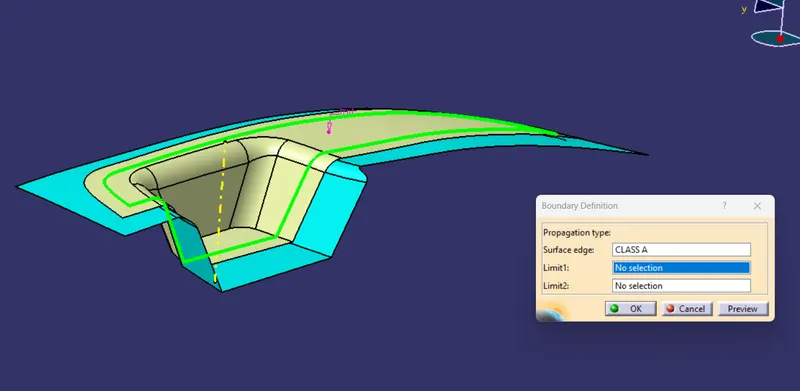
PARTING LINE:
A parting line is an inevitable part of injection molded products. It is the line of separation between where two halves of a mold meet. It manifests itself on injection molded parts as a line that runs the entire perimeter of the part. In most parts, it is just a line that runs straight down the middle.
Now create a insection between the above trimmed surface with class B surface.
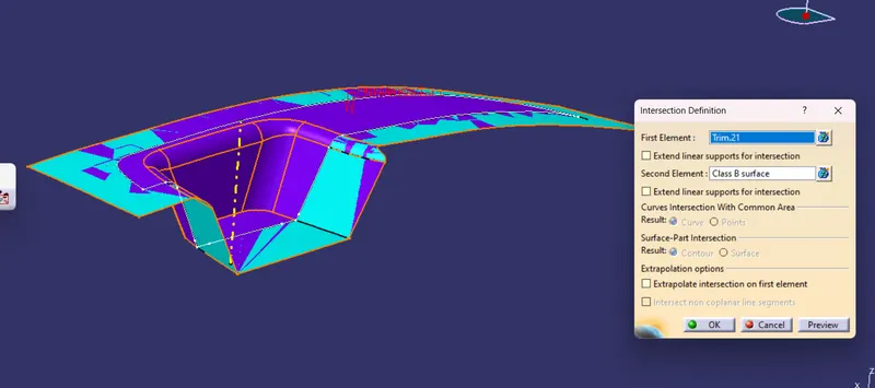
Split the trimmed surface with the parting line above to get the final parting surface.
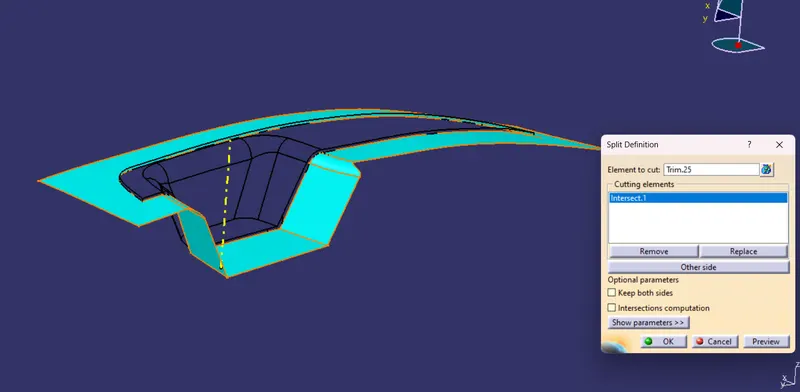
4) Core Block Design:
Create a rectangular sketch along the XY plan of the axis system.
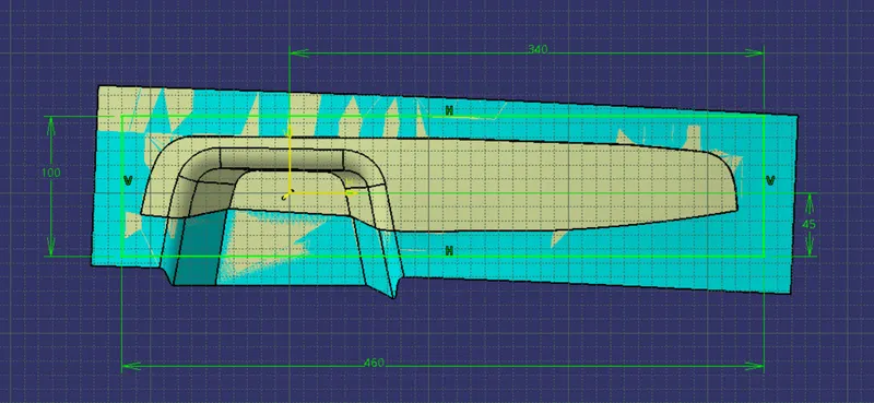
Extrude the stketch and trim it with the untrimmed parting surface.
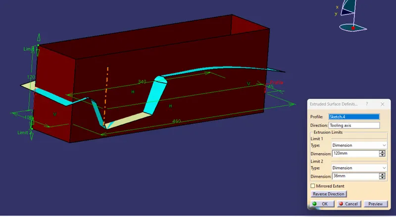
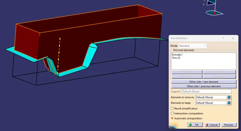
Fill the above open surface, then join the both and create the solid of the same with the Close surface command in part design workench.
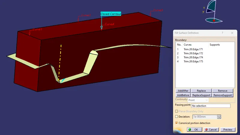
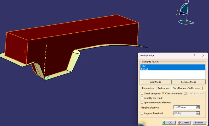
Now the core block is created. Publish the same further using publication option.
5) Cavity Block Design:
Now trim the extruded rectangular surface with the parting surface again in different direction as shown below.
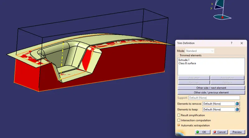
Fill the above open surface, then join the both and create the solid of the same with the Close surface command in part design workench.
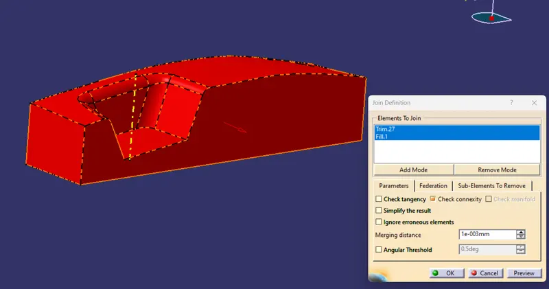
Now the core block is created. Publish the same further using publication option.
To verify whether the blocks are created properly or not create a the insections of the parating surface, core block and cavity block along the ZX plane to check and change the colour accordingly of the same for better understanding anf visualization.
Different Views: