Week 8 - Challenge 6 - Core & Cavity Design
Core and Cavity Design for Switch Bezel - Plastic Component Mold
This report demonstrates the design of Core and Cavity Bloacks for an Automotive Plastic Component – Door Switch Bezel using industry principles such as Parting Surface and Parting Line definition, Draft angles, Draft Analysis, Determining and implementing of Tooling Axis, Class A, Class B, Class C surfaces and maintaining the Thickness of the part at 2.5mm. The Molds are designed using Surface Design and Solid Design techniques in CAD package CATIA V5.
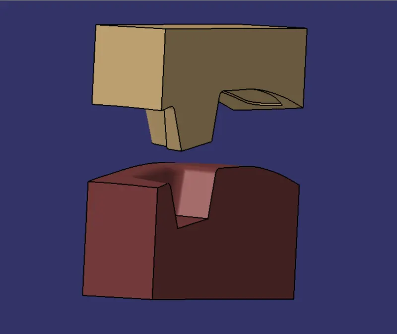
Figure1: Core and Cavity for Switch Bezel
The terms are briefly explained below:
Parting Surface:
- Generally Injection Molding has 2 major components: the Movable Half and the Fixed Half.
- During Injection Molding process, these 2 halves are pressed together tightly to form a sealed hollow to avoid the melt flow leakage and maintain certain holding pressure.
- The pressed surface is called the Parting Surface.
- Usually the parting surface are the biggest projection outline of the part.
- Parting Surface directly affects the Product Quality, Ease of Construction and Operation of the Injection of the Mold, the Mold Design is one of the key factors to the success.
- Design of Parting Surface should follow the following Design Principles:
- Designing the Mold Structures as simple as possible.
- Avoid or reduce side parting as much as possible to reduce complexity of mold making.
- Ease of De-Molding. The plastic component must stay at the fixed half in most cases and ejected by the Ejection System and avoid side De-molding action.
- Ensure Dimensional Acccuracy of the molded parts and try to make parts with similar dimensional accuracy requirements in the same module to reduce manufacturing and assembly errors.
- Ensure Appearance Requirement of the molded parts.
- Flash or mismatch usually occurs on the Parting Surface, so it shoul not be designed on a High quiality requirement Surface.
- Ensure adequate Venting or De-Gassing. If possible Parting Surface should be placed at the end of the Mold Flow. This can be a good advantage for Filling and Venting.
- Parting Surface of Switch Bezel is shown in Figure 1.1.
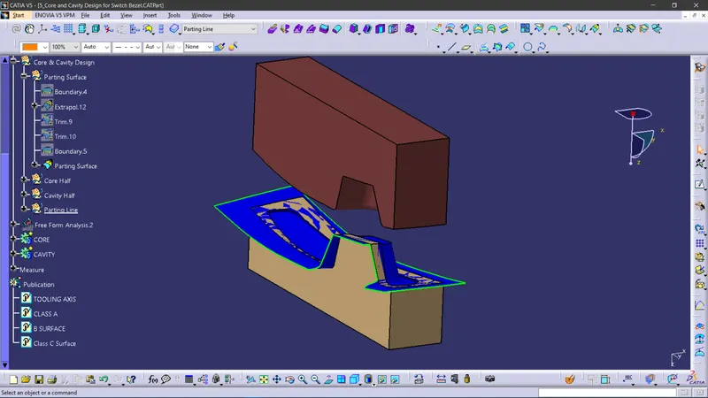
Figure1.1: Parting Surface Highlighted in Blue
Parting Line:
- Intersection of the Plastic Component with the Parting Surface is called the Parting Line.
- It is the Bordered Outline of the Component along the Parting Surface.
- Parting Line of Switch Bezel is shown in Figure 1.2
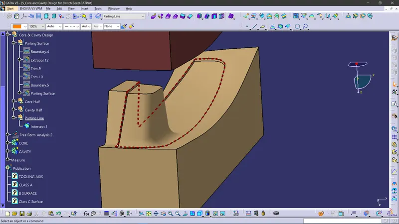
Figure1.2: Parting Line Highlighted in Brown dotted Line
Draft:
- Draft is an angular tapering given at the design stage to every Plastic Component that has to be manufactured.
- It is given in the direction of the Mold Movement.
- The Draft allows the parts to release easily from the mold without creating friction between the surface of component and the core and cavity plates.
- When a Plastic component cools down inside the mold, the natural tendency of it is to shrink and attach to the core or cavity half.
- The movement of mold opening causes friction on the walls of the component as well as the core/cavity blocks.
- This reduces the life of the mold as well as the component itself.
- The component may also have rough surface finish as well as weak structure due to this.
- This problem can be solved by giving draft to the component.
- Most applications require minimum draft angles of around 0.5º to 1º , however 3º draft angles are widely accepted for cost saving purpose.
- 7º Draft angles are given to textured surfaces like Instrument Panels.
- Minimum possible draft angles are given to screw bosses, ribs and stiffeners due to their critical nature.
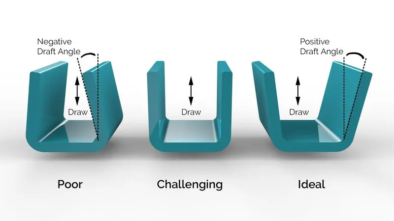
Figure2: Draft Angles
Tooling Axis:
- Tooling Axis is the direction in which the Mold opens and closes. Part Drafts are given along this axis.
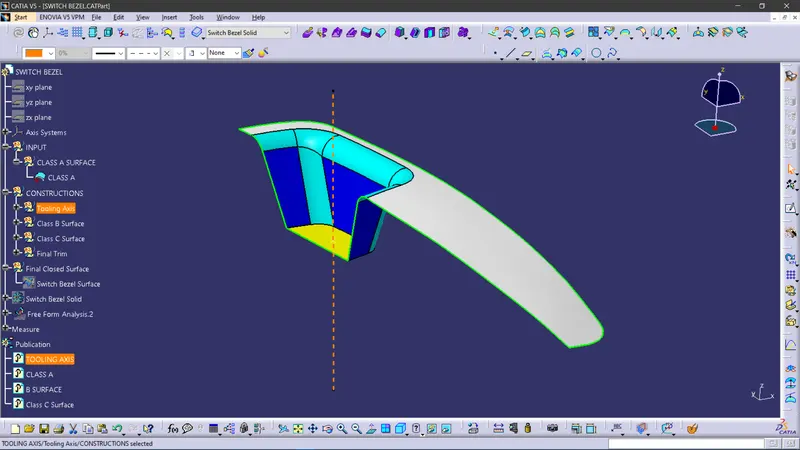
Figure3: Tooling Axis
Draft Analysis:
- Draft Analysis is a tool in CATIA which identifies the zones which deviates from the specified values of angles along a defined draft direction using colour codes.
- It highlights the regions of draft using colours.
- Draft analysis is the first step performed after receiving the Class A of the component.
- Draft analysis should be passed in order to make the plastic component manufacturable.
- Acceptable draft angles are used as range for draft analysis.
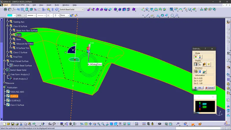
Figure4: Draft Analysis showing one of the faces having acceptable 4.2º draft angle
Class- A Surface:
- In automotive design, a class A surface is any of a set of freeform surfaces of high efficiency and quality.
- It is the visible aesthetic surface of any automotive component.
- Class A surface refers to those surfaces which are visible and abide to the physical meaning, in a product.
- This classification is primarily used in the automotive and increasingly in consumer goods industry.
- It is a requirement where aesthetics has a significant contribution.
- For this reason, the exterior of automobiles is deemed Class-A.
Class- B Surface:
- Class B surfaces are Engineering Surfaces which are invisible to the eyes or often on the back side of the Class A surfaces.
- It is mainly the thickness of the component or Class A.
- These surfaces need to be designed as per the Class A surface i.e., the continuity, thickness of the component, functionality etc should be maintained.
- These surfaces include the main engineering features such as Screw bosses, Ribs, Snaps, Stiffeners and fixations.
- B surfaces also do not contain any aesthetic styling content and textures since it is not visible to eyes.
Class- C Surface:
- Class C surfaces are connectors between Class A and B surfaces.
- This surface connects both A and B surfaces along the Tooling Axis.
- It contains the draft as per the design.
- It is basically the thickened surface between both A and B surface.
- Below Figure 5 shows class A,B and C surfaces: Blue surface is Class A, Purple surface is Class B and Red surfaces are Class C surfaces.
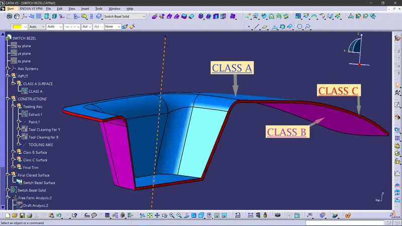
Figure5: Depiction of Class A, Class B and Class C surfaces
SWITCH BEZEL DESIGN:
Procedure to be followed:
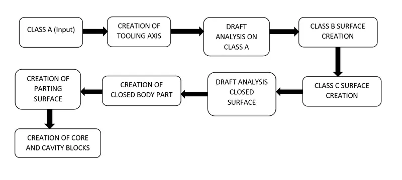
Figure6: Procedure in designing Switch Bezel AND Its Mold
Step 1: Design Check on received Class A:
- After receiving the Class-A for the Switch Bezel check for the connectivity of the surfaces on it.
- Use Join operation, boundary operation and disassemble.
- The check is over if any discontinuities do not arise.
- Delete the operations after the check.
Step 2: Determine the Tooling Axis:
- Identify faces which can potentially create problems while manufacturing.
- Surfaces at angles along a desired Tooling Axis.
- Extract a plain surface and create a point on its center for Axis system creation.
- In this case Z axis can be a possible Tooling Axis Direction.
- The Blue and Cyan Faces can be a problem in terms of draft analysis Figure 7 demonstrates the steps.
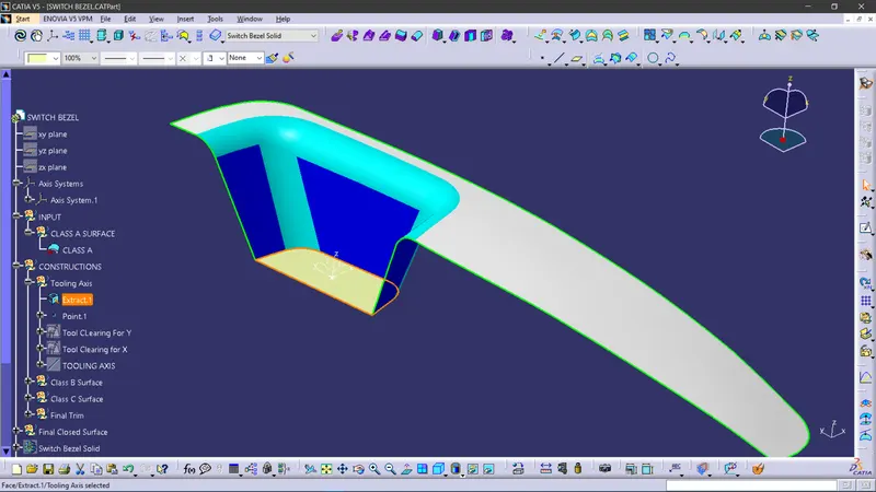
Figure7: Base Extract and Highlighted problematic Faces for Draft Analysis
- Create a sketch on YZ Plane creating Intersects for the 2 Faces.
- Create a Bisecting Line for the 2 intersects and it will be the Tool Clearing Axis for Y.
- It is shown in Figure 8.
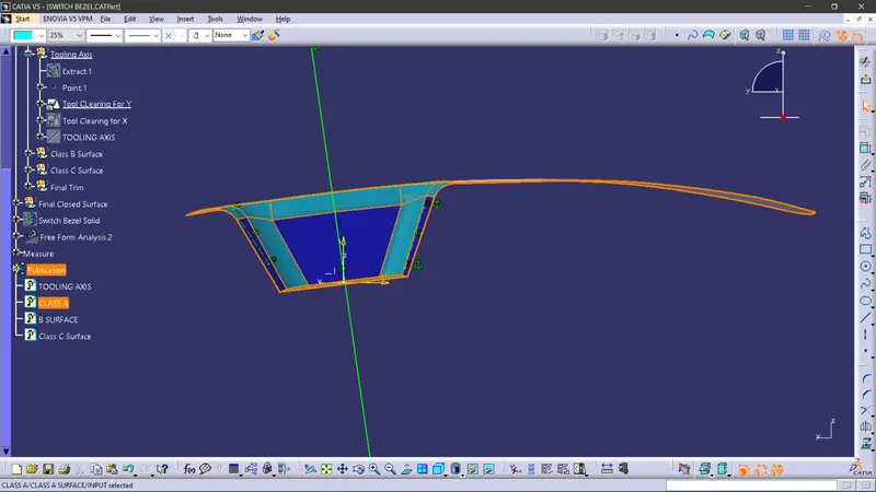
Figure8: YZ plane sketch for Tool Clearing for Y.
- Do the similar Sketch process in XZ plane.
- In this case there is only 1 wall for intersection with XZ Plane.
- For such cases, Sketch a Line at an angle greater than acceptable draft angle from the axis center origin on the same XZ plane.
- The angle chosen here is 7º.
- This Line itself is the Tool Clearing Axis for X, rename it with the same.
- It is shown in Figure 9.
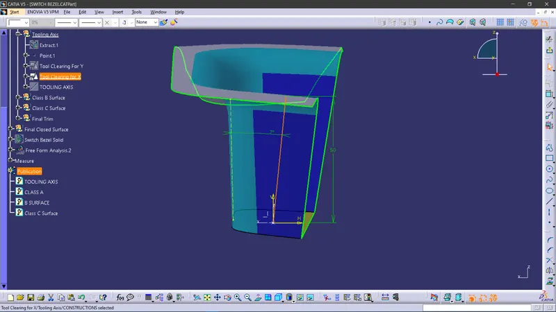
Figure9: XZ Plane sketch for Tool Clearing for X.
- Create a Bisecting Line for both Clearing Axes and name it as Tooling Axis. It is shown in Figure10.
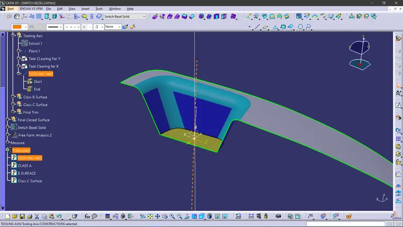
Figure10: Bisecting Line renamed as Tooling Axis.
- Publish the Tooling Axis as well as the Class A for easy access using Insert à Publication as shown in Figure 11.
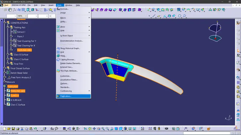
Figure11: Publication of Tooling Axis and Class A surface.
Step 3: Perform Draft Analysis on Class A Surface:
- Change View Mode Customization to Material mode
- Go to INSERT ---> ANALYSIS ---> FEATURE DRAFT ANALYSIS and move the compass to the Tooling Axis.
- Change the range to 3º. Apply the settings as Shown in Figure 12
- As shown the target area has 4.2º draft angle which was the concerned face.
- Thus, it passes the criteria of having suitable draft and the Class A can be further designed into a solid plastic component and manufactured.
Figure12: Draft Analysis on Class A of Switch Bezel.
Step 4:Class B Surface Creation:
- Extract the relevant surfaces from Class-A surface which excludes the Fillets and holes.
- Here the selected faces consist of Bezel Arm rest surface, Walls and the Base surface.
- Extract of these surfaces is shown in the Figure 13.
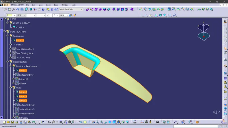
Figure13: Extract of surfaces from Class A of Switch bezel.
- Use Untrim Command to untrim the extracted surfaces and create a natural extend.
- It is shown in Figure 14.
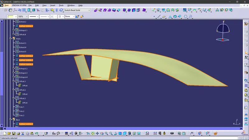
Figure14: Untrim of Extracted Surfaces.
- Extrapolate the untrimmed surfaces so that each of them intersects clearly and pass way forward than the Class A which will help in its trimming in further operations.
- The operation is shown in Figure 15.
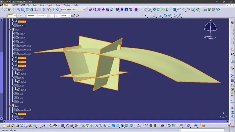
Figure15: Extrapolated Surfaces created from Untrimmed Surfaces.
- Offset the extrapolated surfaces to the value of required Thickness of the Part.
- In this case of Switch Bezel, the thickness value is 2.5 mm.
- The offset faces are the part of B-Surface.
- The operation is shown in Figure 16.
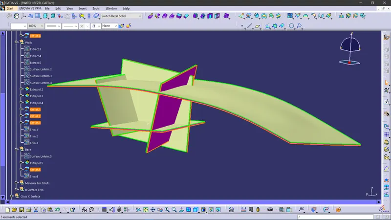
Figure16: Offset highlighted in Purple.
- Trim the extra surfaces to obtain similar extended surfaces as in Class A.
- The surface obtained after trim is shown in Figure 17.
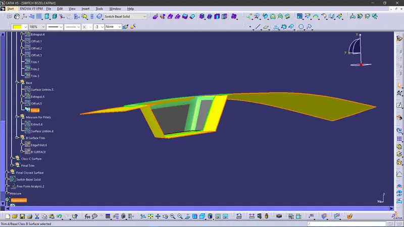
Figure17: Surface obtained on Trimming of Extrapolated Surfaces.
- Create Fillets while maintaining the part thickness between the Class A and Class B surfaces.
- The Value of Fillet is given by the equation (B surface fillet = A surface fillet ` Thickness of the Part).
- The sign + or – must be decided so as to maintain the part thickness which in this case is 2.5mm.
- The operation is shown in Figure 18.
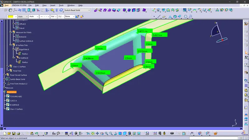
Figure18: Fillets to be created as per the Part Thickness (in this case 2.5mm).
- The obtained surface is the required Class B Surface highlighted in Light Brown as shown in Figure19.
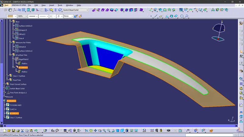
Figure19: Class B surface of Switch Bezel highlighted in Light Brown.
Step 5: Class C Surface Creation:
- Use Multiple Extract to extract the outer boundary of the Switch Bezel Class A surface.
- Use Smooth Curve since the multiple extract creates multiple sections as shown in Figure 20.
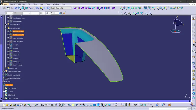
Figure20: Multiple Extract and Smooth Curve for Class A boundary.
- Use Sweep Operation to extrude the boundary using the Draft direction option and selecting the Tooling Axis as the direction.
- Use draft angle as 3º and select outward direction arrow.
- Sweep it well beyond the B surface as shown in Figure 21
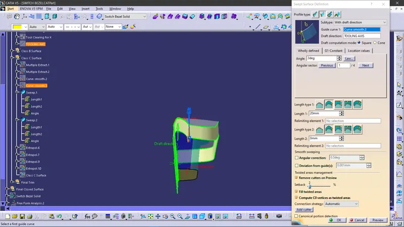
Figure21: Sweep operation with draft direction and draft angle.
- Use similar Sweep for other Smooth curve and if any gaps are found extrapolate and trim to make an enclosed surface.
- The C surface is shown in Figure22
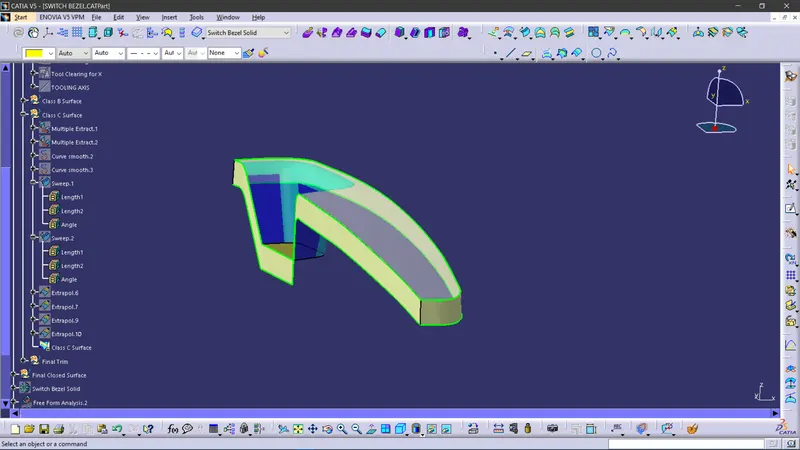
Figure22: Class C surface.
Step 6: Final Closed Surface Creation:
- Join all the Swept surfaces along with the Class A Surface. In this case gaps occur while joining so use 0.003mm.
- Even this method doesn’t fill up the gap so extrapolate Class A to about only 0.5mm and trim it off with C surface.
- The Final trim should be one single Surface Entity without any gaps as shown in Figure 23.
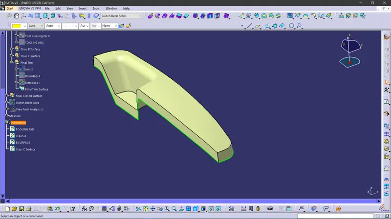
Figure23: Final trim of Class A and Class C surfaces.
- Trim the Final Trim Surface with the Class B surface to obtain the final enclosed Surface for the Switch Bezel as shown in Figure 24.
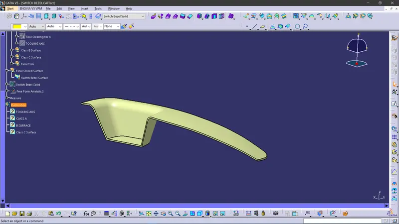
Figure24: Final Closed Surface.
Step 7: Perform Draft Analysis on the Final Closed Surface:
- Change View Mode Customization to Material mode
- Go to INSERT à ANALYSIS à FEATURE DRAFT ANALYSIS and move the compass to the Tooling Axis. Change the range to 2.9º. Apply the settings as Shown in Figure 25
- As shown the target area has 3º draft angle. Thus, it passes the criteria of having suitable draft and the Closed can be further designed into a solid plastic component and manufactured.
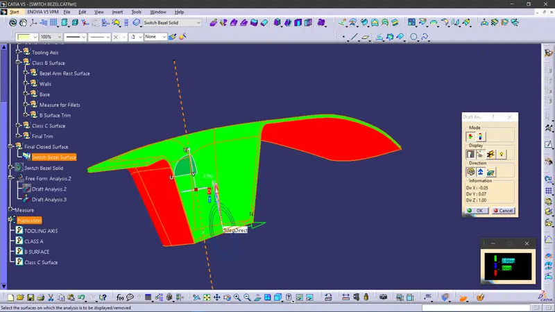
Figure25: Draft Analysis on Closed Surface of Switch Bezel.
- Other views of the Draft Analysis are shown below in Figure 26 to Figure 29
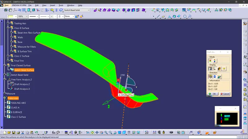
Figure26: Isometric View - Draft Analysis on Closed Surface of Switch Bezel.
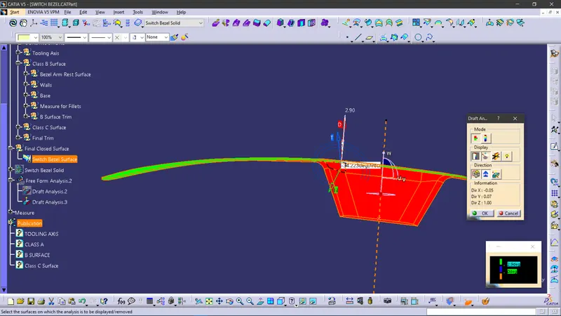
Figure27: Front Side View - Draft Analysis on Closed Surface of Switch Bezel.
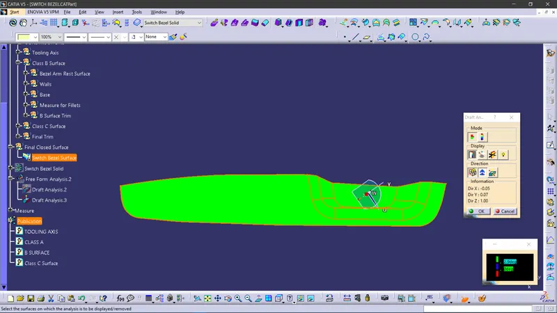
Figure28: Top View - Draft Analysis on Closed Surface of Switch Bezel.
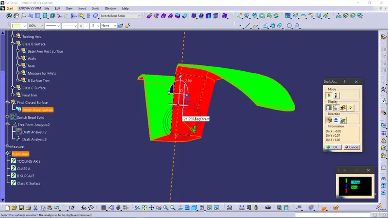
Figure29: Left Hand Side View - Draft Analysis on Closed Surface of Switch Bezel.
Step 8: Create a Closed Body Part from Final Closed Surface:
- Switch to Part Design Workbench and use Closed Surface option to create a Solid Part from the final obtained surfaces.
- The part created is the required Switch Bezel designed from a Class A.
- The obtained solid Part is shown in Figure 30.
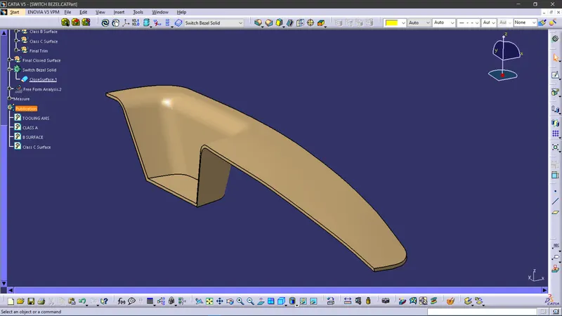
Figure30: Final Closed Surface Part of Switch Bezel.
MOLD DESIGN FOR THE SWITHC BEZEL:
Step 9: Creating Parting Surface:
- Use Boundary Operation to extract the boundary of the Class A Surface as shown in Figure 31.
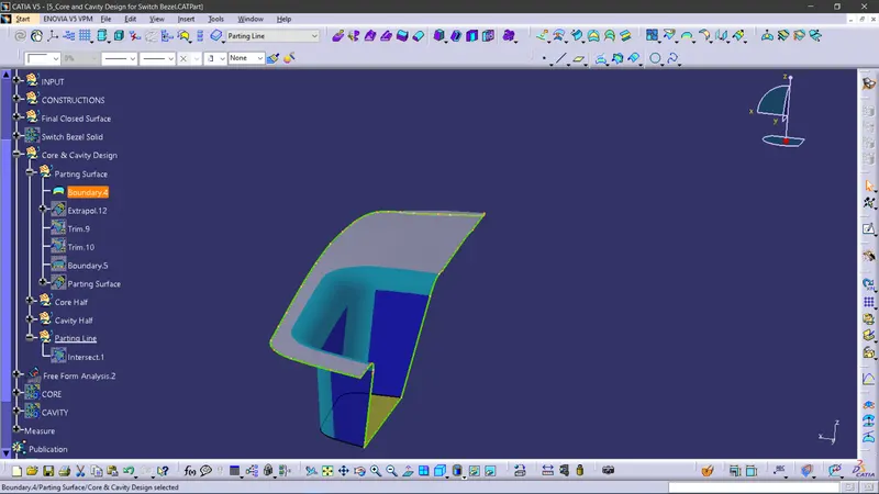
Figure31: Boundary extract of Class A of Switch Bezel.
- Extrapolate the Boundary with appropriate Value and Trim it with the Class C surface as higlighted in blue in Figure 32.
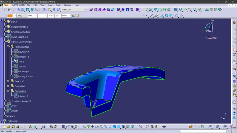
Figure32: Trim of Extrapolated section with Class C surface.
- Trim this with the B Surface to get the outcome as in Figure33.
- This is the required Parting Surface.
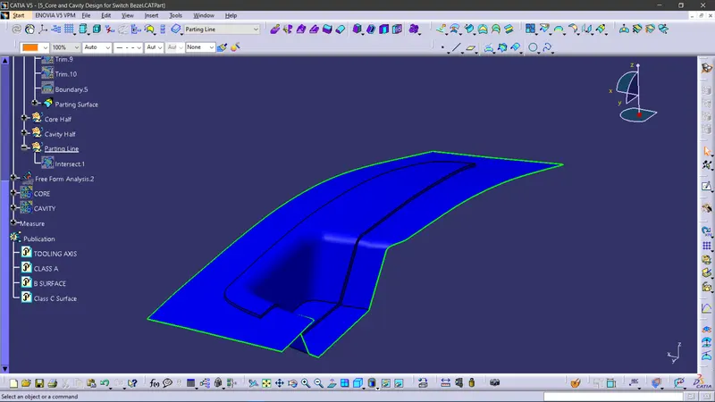
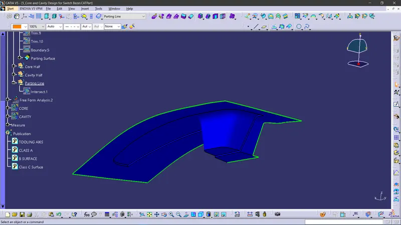
Figure33: Parting Surface for the Switch Bezel Molds.
Step 10: Creating of Core And Cavity Blocks:
- Create a rectangular sketch on the Plane - Normal to the Parting Surface aand Extrude the Sketch to create the Core surface
- It is shown in Figure 34.
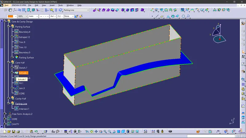
Figure34: Extrude Created for Core Block for the Mold.
- Extraxct the outer top boundary of the Core Block and Fill the top to create a closed Surface.
- Join the Fill surface and the Extrude of Core
- Trim it with the Parting Surface to obtain the Core Block eclosed Surface as shown in Figure 35.
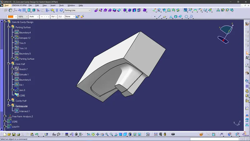
Figure35: Core Block for the Mold.
- For creating Cavity Block Extrude the same sketch on the opposite side and create Fill and Join the Surfcace as shown in Figure 36.
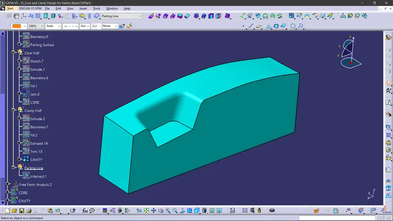
Figure36: Cavity Block for the Mold.
- Use The Intersection of Final Trim and the Parting Surface for Creation of Parting Line as shown in Figure 37.
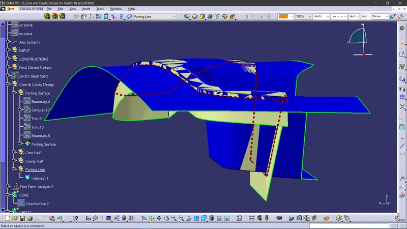
Figure37: Parting Line in Brown Dotted Line.
- Switch to Part Workbench and convert the Surfaces to solid part
- Use Closed Surface to create Solid Part for the Core and Cavity Blocks.
- The Figure 38 shows the Part of Core and Cavity Block as Solids, The light brown is Core Part and The Dark Brown is the Cavity Block
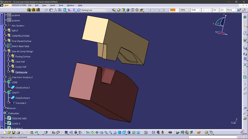
Figure38: Core and Cavity Block for the Mold of the Switch Bezel.
Conclusion:
The Design of Core and Cavity for the Mold of Automotive Plastic Component – Door Switch Bezel is completed using concepts of Parting Surface, Parting Line, Draft angle, Draft Analysis for Class A and Final enclosed surface, Tooling Axis creation and implementation, Class B and Class C creation and conversion to a solid part maintaining the part thickness at 2.5mm.