SUNSEEKER PREDATOR YATCH
1. Radar Mast
Report:-
TITLE: Design, assembly, and rendering of sunseeker predator 108 Yacht.
OBJECTIVES:
- To design, assemble and render the Sunseeker predator 108 Yacht.
- To learn the designing complex surfaces in Solidworks.
- To learn the Solidworks software as a design tool in an industrial manner.
- To be industry ready for the role of Mechanical Design Engineer.
INTRODUCTION:
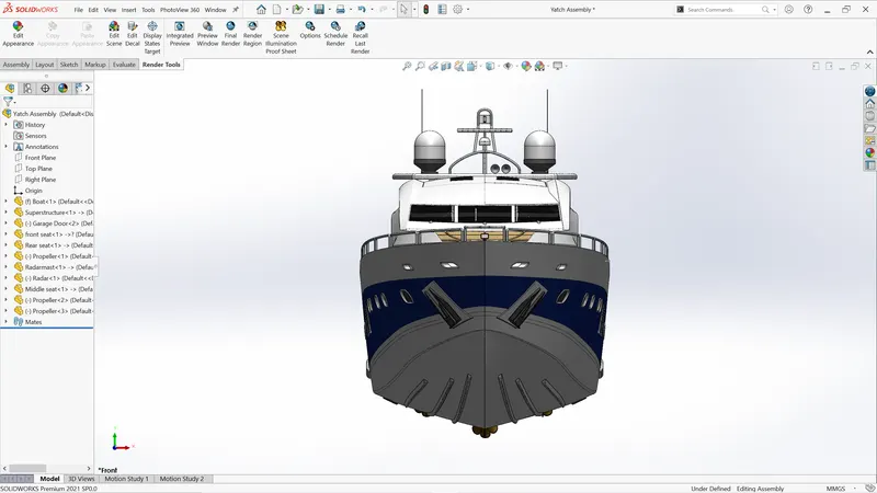
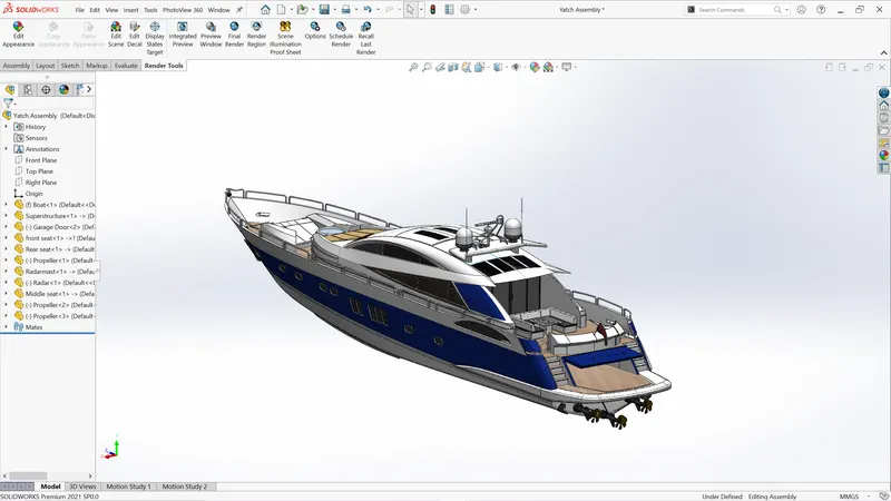
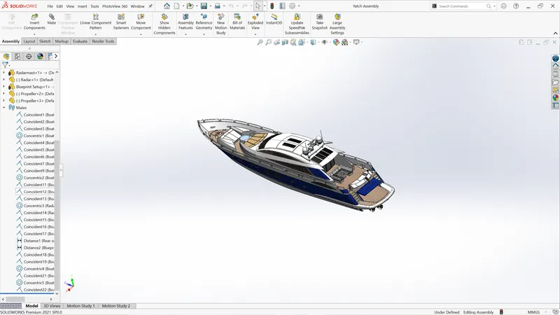
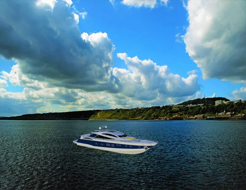
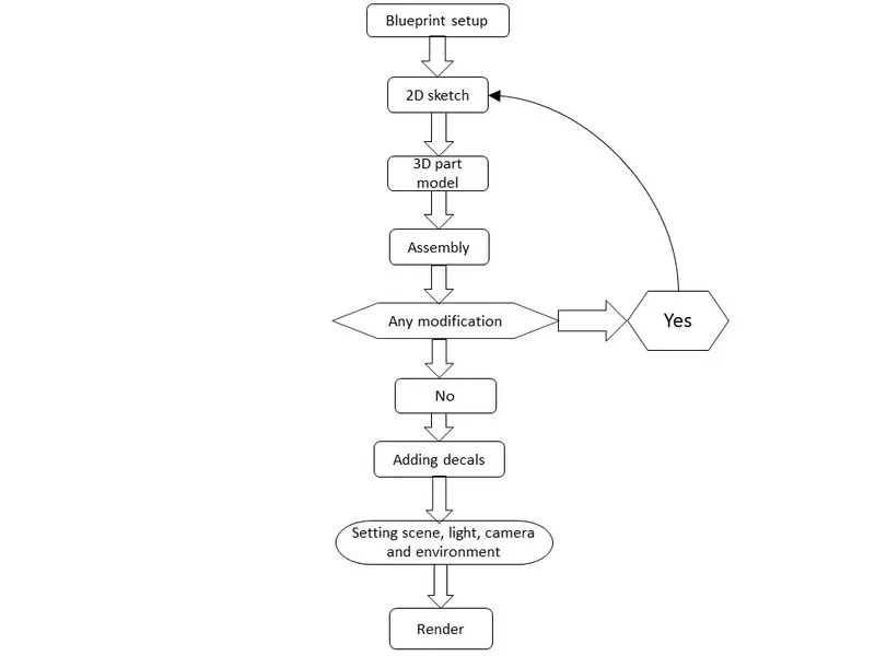
In this project, I built a sunseeker predator108 yacht. The design started with creating a blueprint setup by setting various views with proper Daimonion and orientation. Then as per the blueprint setup, all the parts are modeled one by one. After that, all parts were assembled in an assembly environment and then rendered using SOLIDWORKS visualize or photo view 360.
DESIGN METHODOLOGY:
A typical sunseeker predator yacht consists of a large no. of parts. But as I am designing a cosmetic model of a sunseeker predator yacht so I focused mainly on prime parts and design them. Once all parts are modeled, they were assembled in an assembly environment. Assembly for this yacht was quite easy because most of the parts were provided with references when they were in the modeling stage. After assembly rendering is done with the help of render tools like photo view 360 and SOLIDWORKS visualize.
DESCRIPTION:
BLUEPRINT SETUP:
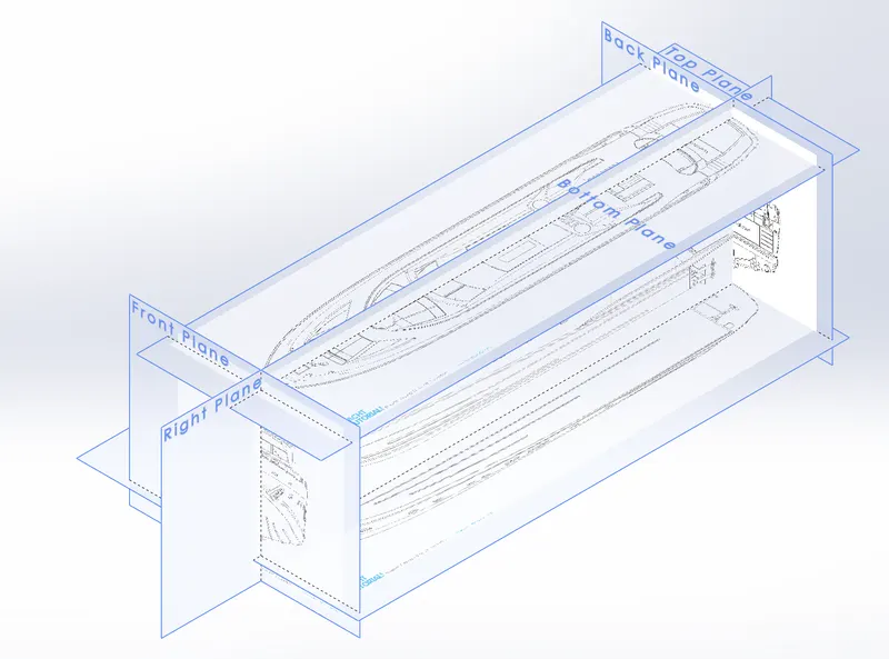
Blueprint setup is nothing but a bunch of different views placed with proper dimensions and orientation. Setup started with creating a different necessary plane and then by using sketch mode on each plane, images with proper dimensions were added to each plane. Technically all the parts of the yacht were designed using the reference of blueprint setup. So, it is very important to set all the blueprints properly with dimensions. If there is any small error in this setup it will lead to a big problem in successive designing.
DESIGN AND 3D MODELLING:
Some of the most important and frequently used feature in this project are described below.
- Extruded surface: The extruded surface is used to extrude sketch contours in one or two directions to create a surface. In this feature, the material is added to the sketch and surface created.
- Lofted surface: The lofted surface is used to create a surface between two edges or sketches. We can also provide no. Of guide curves to control the path shape.
- Fill surface: Fill surface is used to fill the gap between edges. It is similar to the lofted surface only difference is, that it requires a close area while the lofted surface can be used with an open area also.
- Trim surface: Trim surface tool is used to remove Extra surface from the intersection between two surfaces or surface and plane or surface and sketch.
- Extend surface: Extend surface tool can perform a function like extending one of the surfaces at the intersection.
- Knit surface: Knit surface is used to combine two or more surfaces and make them a single surface body.
- Extrude: This is the main feature for converting 2d sketches into 3d models. While extrusion material is added to the sketch.
- Extruded cut: The extruded cut is a similar feature to extrude but instead of adding material it removes material from the body
- Revolve: Revolve feather used for creating circular bodies about the central axis
- Project curve: Project curve feature converts two different Sketches from two different planes into a single 3d curve. The project curve feature is very helpful for creating complex geometry.
- Rollback: Rollback is a powerful feature that gave us access to edit the parent feature without disturbing the child feature (most of the time). rollback is widely used to remove errors from the parent feature or add some more functions to the parent feature.
PART DESIGN:
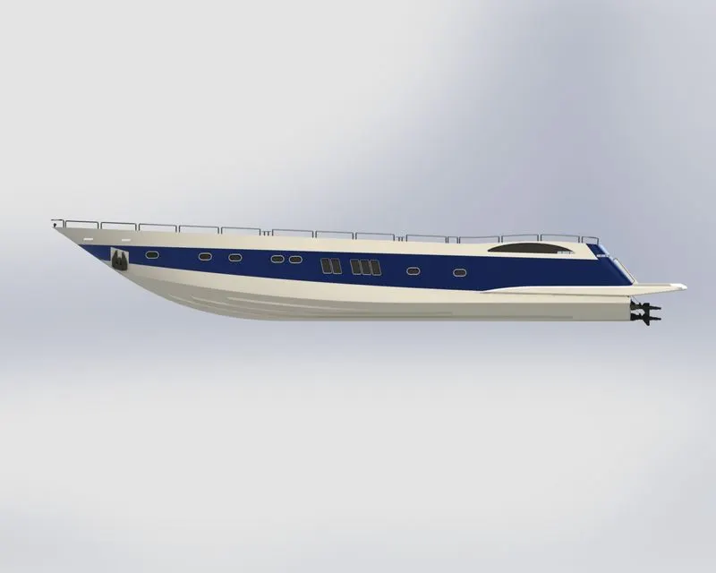
- HULL:
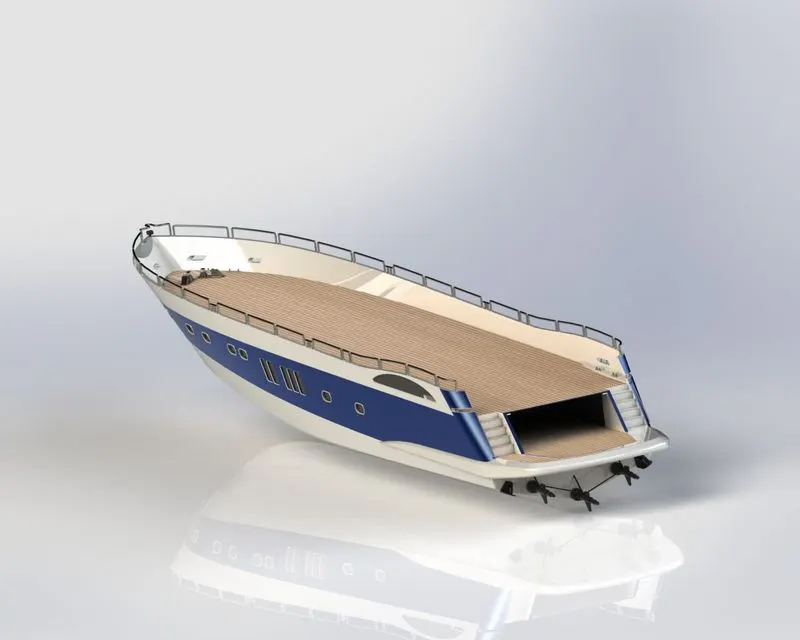
While designing a yacht we can say the hull was the most important part. Because it is the hull that bears all the load and creates a water lift to move the giant marine vehicle. For designing the hull, I started with creating curves similar to a blueprint. And then by using surface tools like a loft, fill, trim, knit, etc I created a closed surface body. I designed this yacht with an industrial approach so I first designed a half hull by creating different surfaces as a closed body and then converted the surface body into a solid. After converting it into a solid body, I mirrored the half hull body about the midplane and created the full hull. For me, the most difficult part while designing the hull was the railings because while creating the railings I had to keep an eye on the relation every moment. The major tools used while designing the hull were surface loft, surface trim, surface knit, boss extrude, and cut extrude. For appearance, I applied decals to the deck, stairs, garage, and lower surface which results in improving the aesthetics of the yacht.
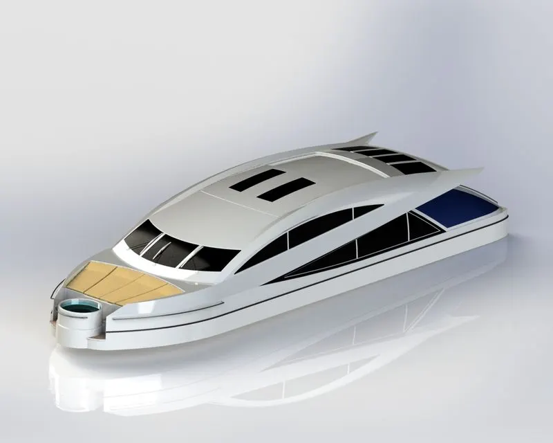
- SUPERSTRUCTURE:
The superstructure is a multi-body part that consists of a cockpit, table, viper, and window. It was also designed half and then mirrored about the midplane which saved lots of time. The design of the superstructure was based on the 3d curves and 3d sketches. 3d curves were created by projecting two different sketches which were made concerning the blueprint. The most frequently used tools while designing superstructure were surface loft, surface trim, surface knit, surface fill, and extended surface. The windshield and other windows were provided with dark colors and another part of the superstructure with a white appearance and for the rest seats using the mattress were, I applied the yellow plastic material.
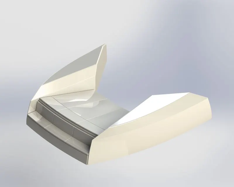
- FRONT SEAT:
Designing the front seat started with creating the curves concerning the blueprint. The major features used during designing the front seat were surface loft, surface trim, surface knit, and cut extrude. A dome was also used to create a mattress-like appearance on the seat. The mattress was provided with a light gray color whereas the other seat surface with white color.
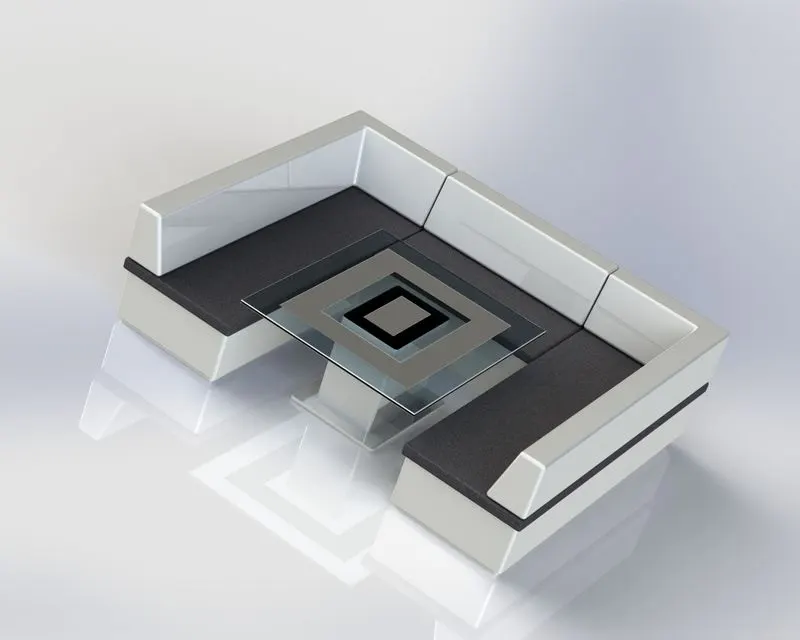
MIDDLE SEAT:
The middle seat is located behind the superstructure. It was created concerning a blueprint on the hull surface. One table was also created with the middle seat. The major feature used during designing the middle seat were boss extrude, chamfer, and fillet. For the mattress, I used the dark gray color for a good look. Since the table is made of glass, the glass table looks more attractive than other plastics table that's why I used the glass top for the table
REAR SEAT:
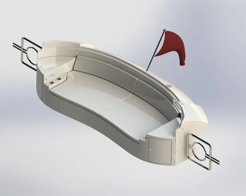
The rear seat was the most complex among the three seats that’s why it was first created as a closed surface body and then converted into a solid body. While designing the rear seat I first create a closed surface body of the half seat by using surface tools like sweep, trim, knit, and loft. The seat was first designed half and then it was mirrored to get the full seat. The major surface tool used for designing rear seats were swept, loft, trim, knit, and extend.
GARAGE DOOR:
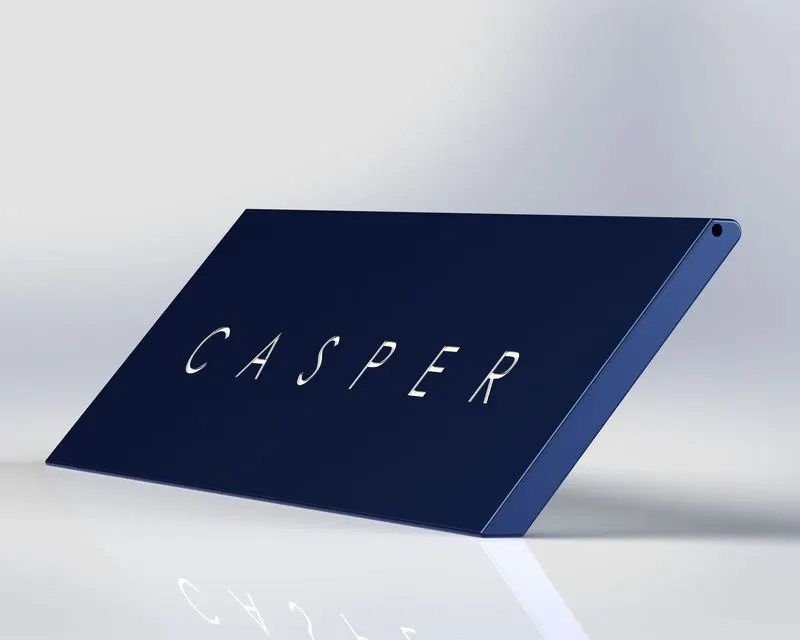
As with the other parts of the yacht, the garage door is also designed in half and then mirrored about the midplane. A garage door was created out of the split block out of the hull. Holes with the help of cut extrude were created on the upper side for pins, through which the garage door will connect to the hull and open and close. The blue color was given as an appearance to it. Caper is my pet DOG
RADAR MAST:
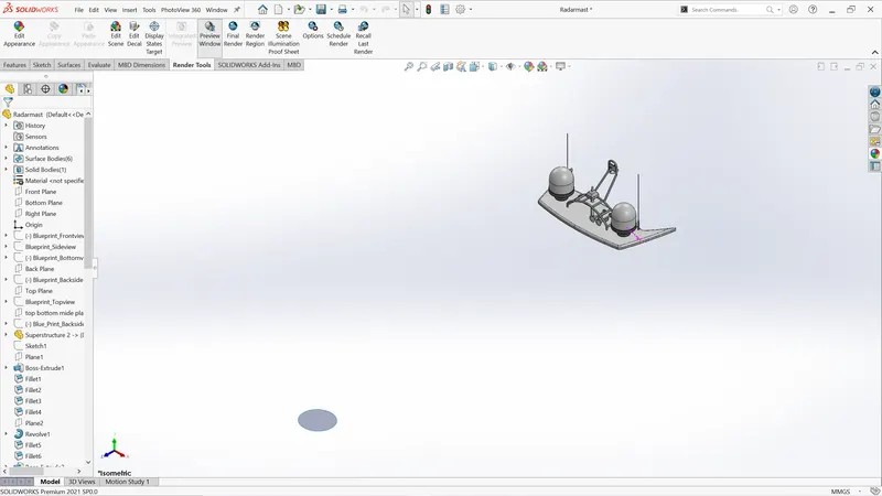
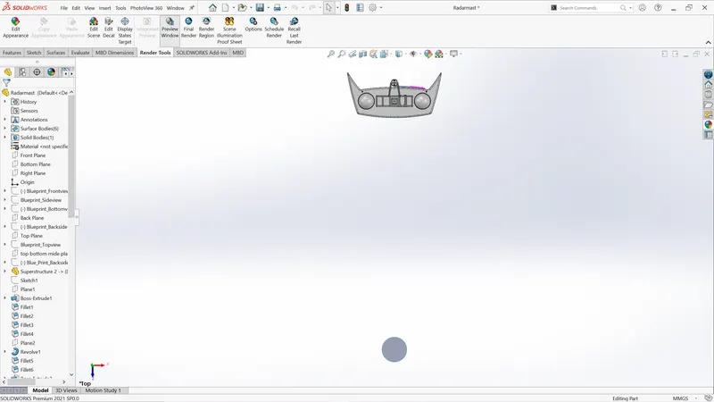
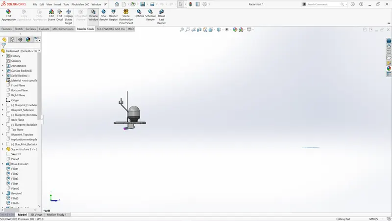
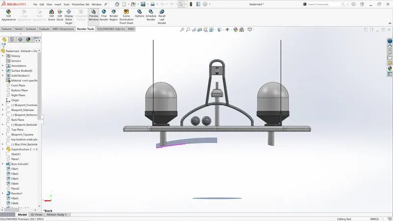
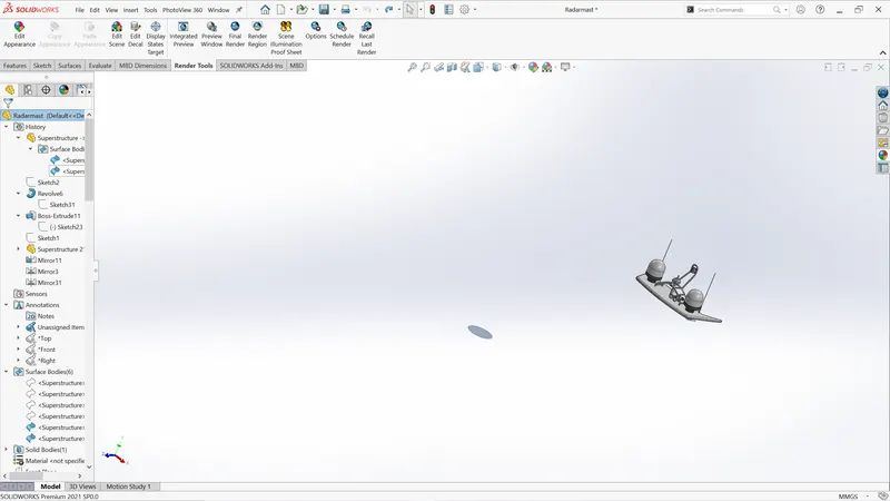
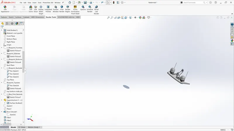
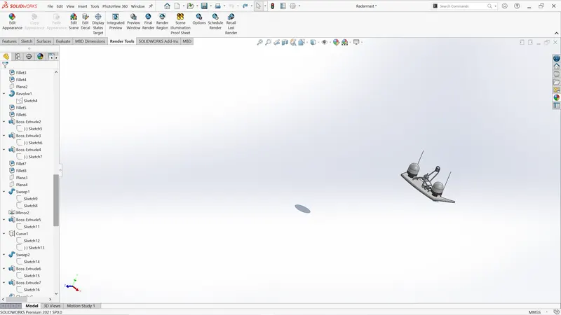
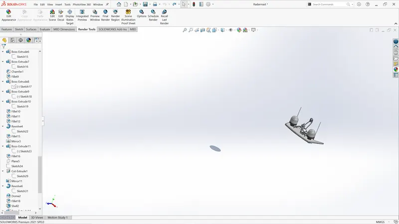
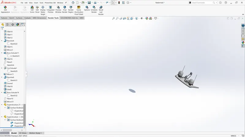
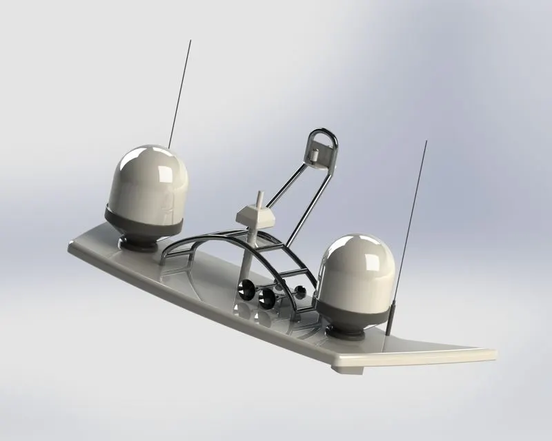
A radar mast is a multi-body part consisting of an antenna, navigation light, foghorn, and radar scanner. Boss extrude, sweep, revolve, fillet and mirror were the main features while creating this part. White color is given as appearance to most of the parts.
RADAR:
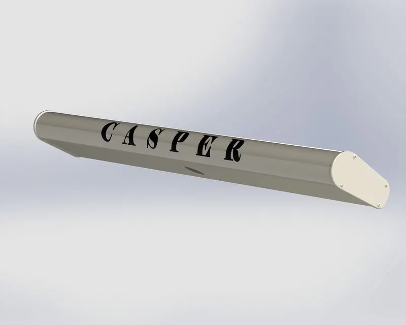
In the marine vehicle, radar plays a crucial role. Radar detects and scans the position of another thing concerning itself. It was created by using extrude and fillet features. One hole is also provided there for rotation of it.
PROPELLER:
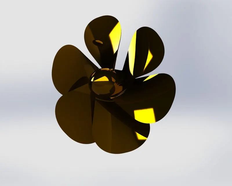
The propeller is responsible for the high speed of the yacht. Due to the pressure difference created by the blades, it moves forward in the water. Revolve, loft and fillet were the key features used while creating the propeller.
RENDERING:
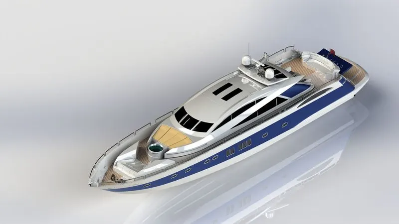
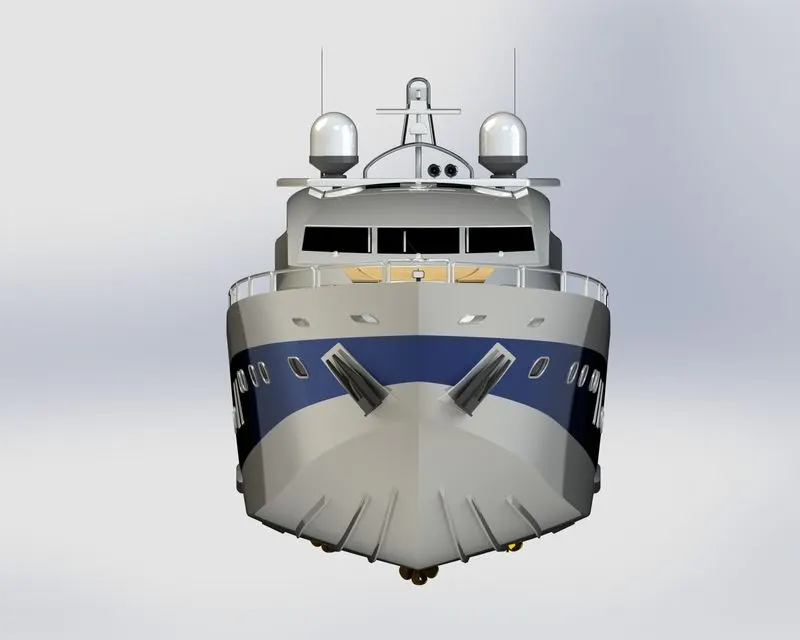
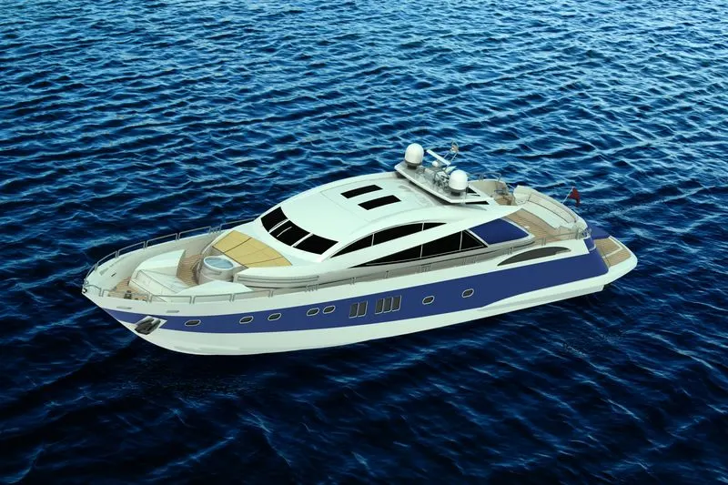
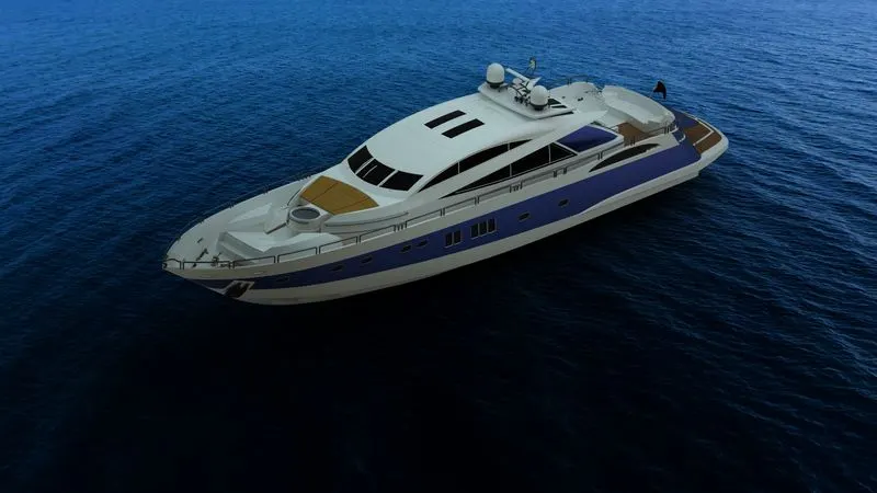
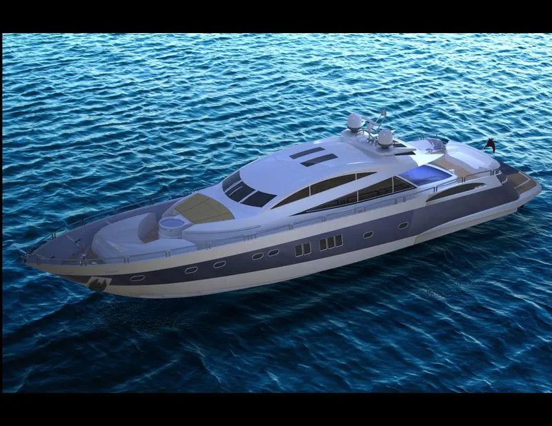
For the rendering of the yacht, I used photo view 360 and SOLIDWORKS visualization. I used photo view for adding decals and visualize for final rendering. In SOLIDWORKS Visualize for the environment, I used the image as a backplate to match the environment with my yacht assembly. Then as per the observed environment, I added some light for creating shadows. And finished rendering high-quality images.
Camera setup view:
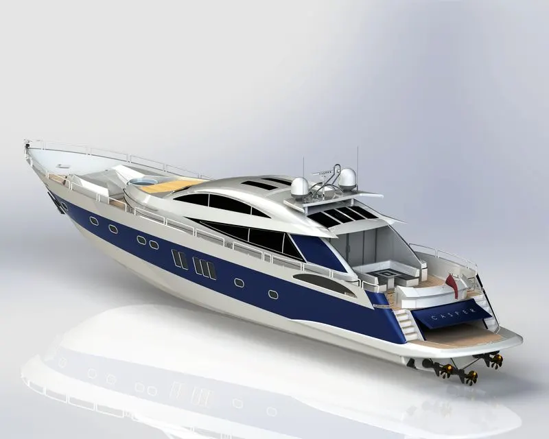
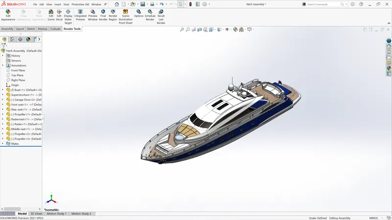
Isometric View:
Front View:
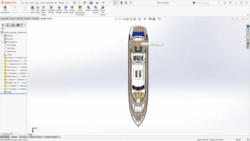
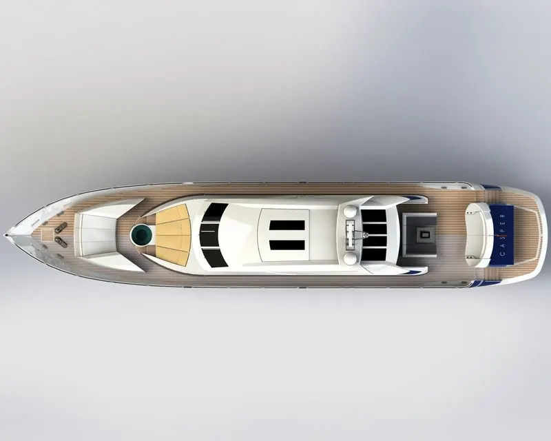
Top View:
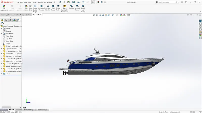
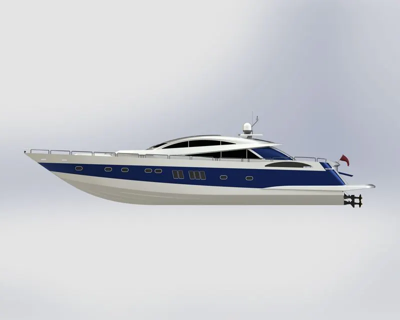
Side View:
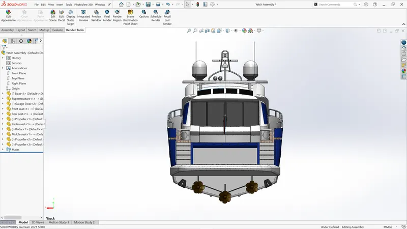
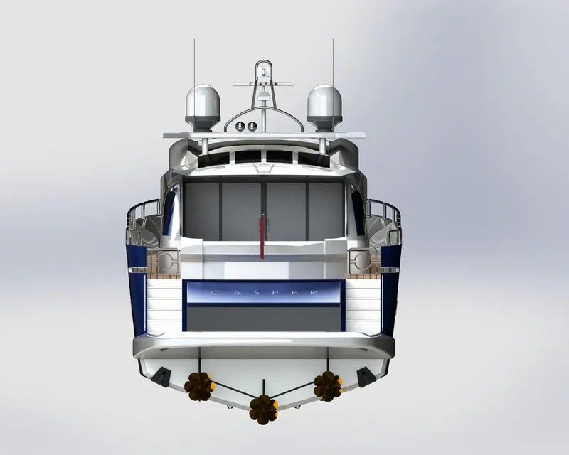
Backside view:-
Additional Render:

CONCLUSION:
Successfully designed, assembled, and rendered the Sunseeker predator 108 yachts. Learned to design complex surfaces in Solidworks. Also learned SOLIDWORKS software as a design tool in an industrial manner. This project helps me to enhance my design skill and help me to become industry ready for the role of Mechanical Design Engineer. Overall, the project was successful.
2. Yacht Assembly