Week 8 - Challenge 6 - Core & Cavity Design
AIM:
- To Create the Core and cavity blocks for the switch bezel component.
DESCRIPTION:
CREATING TOOLING AXIS -
The Tooling Direction refers to the general path that a part is pulled in when it is being formed in a mould. Essentially, the mould is constructed using two distinct components that are joined together. One of your sides is the Core side, while the other is the Cavity side. When the Core is pulled away from the Cavity in this direction, the Dye line (also known as the Tooling Direction) may be seen.
- Launch the CAT part file that was provided.
- To check for gaps between surfaces, click the join button, and then click the preview button.
- If there is any space between the two surfaces, you should attach them with a tolerance of no more than 0.003 millimetres.
- The border should be extracted, and then the boundary should be disassembled.
- Find the correct tooling axis so that the elements can be generated without the tooling axis being obstructed by the material.
- Generate an axis for the system by using the switch's middle position.
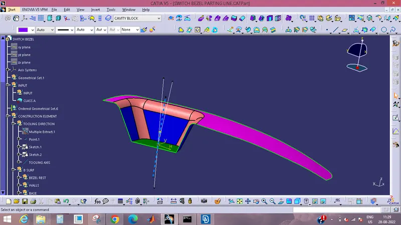
By bisecting two axes that originate in the x and y planes, the tooling axis for the component can be generated.
DRAFT ANALYSIS
Using the Draft Analysis command, you will be able to determine whether or not the component that you drafted will be simple to remove. This kind of analysis is carried out based on colour ranges that designate areas on the element that is being evaluated in which the deviation from the drafting direction at any point corresponds to predefined values.
- Go to customised view parameter first, then under mesh, then check material, and then click ok to finish. Do this before proceeding to the draft analysis.
- To view the drafting analyses at this point, navigate to insert » analysis » feature drafting analysis.
- Compass bearings should be used to determine the direction of the draught.
- Adjust the draught angle on the colour scale such that it reads 3 degrees.
- When the passing drafting angle is detected, the component will change from red to green.
- Check the angle of the component with the help of the running point.
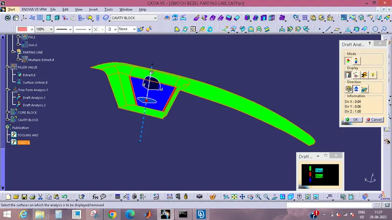
- The preliminary analysis i.e draft analysis has been finished.
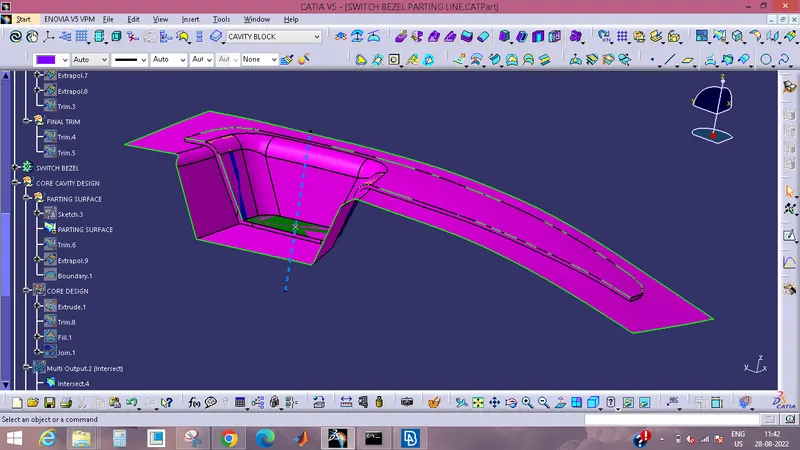
PARTING SURFACE
- Typically, an injection mould will have two major components: the movable half and the fixed half. During the injection moulding process, these two halves will be pressed tightly from a sealed hollow in order to prevent the melt flow leakage and maintain a certain holding pressure. The pressed surface will be known as the parting surface, and it will typically be the projection outline of the part that is the largest.
CORE DESIGN
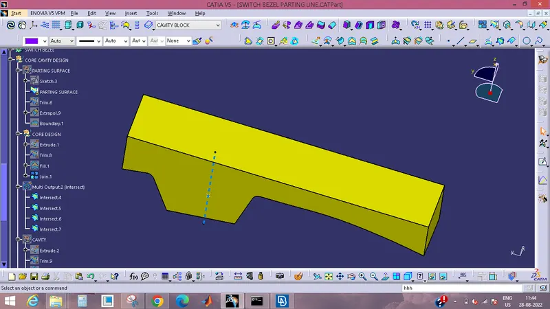
- A hollow part's interior is formed by the core, which is a section of the mould that is placed into a cavity to do so.
- Core-cavity is a phrase that is used to describe a mould that is made by mating together the A-side and B-side portions of the mould.
CAVITY DESIGN
- A plastic component is produced by having plastic injected into a mould, which is a hollow form commonly formed of stainless steel. Molds are used in the manufacturing process.
- The plastic is put into the cavity of the mould, which is a hole in the mould that is fashioned like the desired item. The mould is then heated.
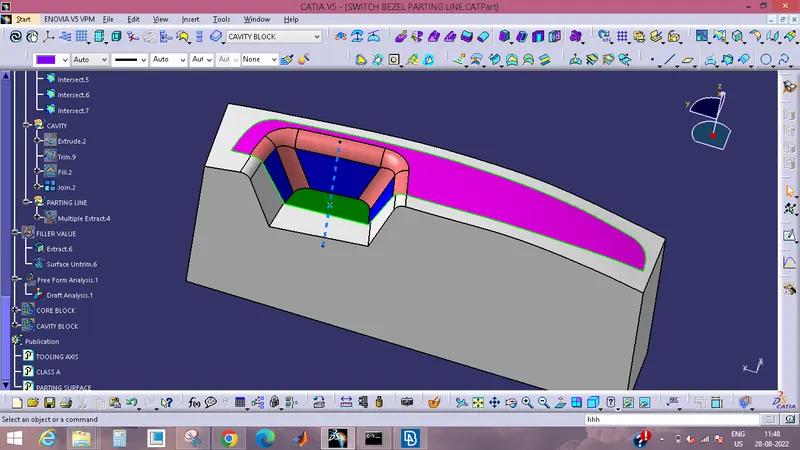
PARTING LINE
- Injection-molded items will always contain a separation line as an unavoidable feature.
- It is the dividing line between the two parts of a mould that have been joined together.
- When it occurs on injection-molded parts, it takes the form of a line that encircles the entire part from one end to the other.
- In most places, it is little more than a line that goes horizontally through the middle.
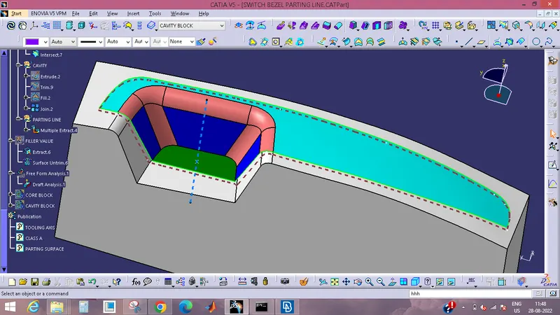
CORE BLOCK, CAVITY BLOCK & PARTIMG LINE TOGETHER
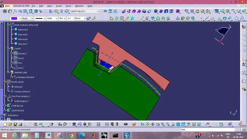
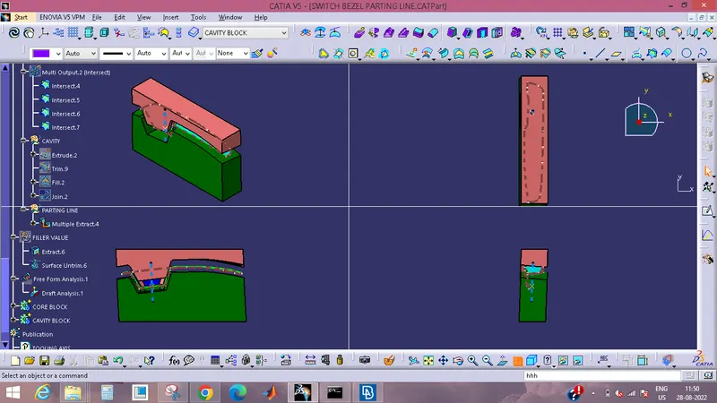
DIFFERENT VIEWS:
PUBLICATIONS
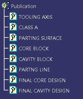
- The component is given a publication in order to improve its visibility and make it simpler to explore.
- To publish the component, pick the tooling axis and the class A surface after going to the tools menu and selecting the publishing option.
- A secondary tree structure develops underneath the primary part of the tree.
CONCLUSION:
The Core and cavity blocks for the switch bezel component are being fabricated at this time.