Week 8 - Challenge 5 - Door Trim Lower
AIM: To Create DOOR trim with thickness of 2.5 with 3 degree draft angle.
we have to create the required Tooling-Axis for the given Class A Surface while meeting the requirements of the necessary Draft Angle & then perform the Draft-Analysis Operation on the Class A Surface itself.
- Class A Surface: Class A is an aesthetic surface with the highest quality finish. Most Class A Surfaces for an Automotive Component are made using 'Autodesk-Alias' based on the final Concept-Sketch. All Class A surfaces should have 'Curvature-Continuity' which means the continuity between the surfaces should share the same boundary. It is taken as a reference by the Automotive Plastic Designer to create 'Class B' and 'Class C' Surfaces.
- Class B Surface: The Class B Surface resides below the Class A Surface at a certain thickness. It is created using Engineering Principles that consist of all the necessary features such as Ribs, Bosses, Snaps, etc. This surface isn't visible to the observer from the outside.
- Class C Surface: The Class C Surface is the surface created between the Class A and Class B surface to join them with each other.
PROCEDURE TO CREATE THE MAIN TOOLING AXIS:
There are two different methods that we can use to create the Main Tooling Axis for our Class A Surface. When we're trying to create our Main Tooling Axis we always have to focus on the direction in which we're going to create the Main Tooling Axis.
- Using a Vertex to create a line along the axis which allows us to view all the holes & exposes the maximum surface area of the Class A Surface.
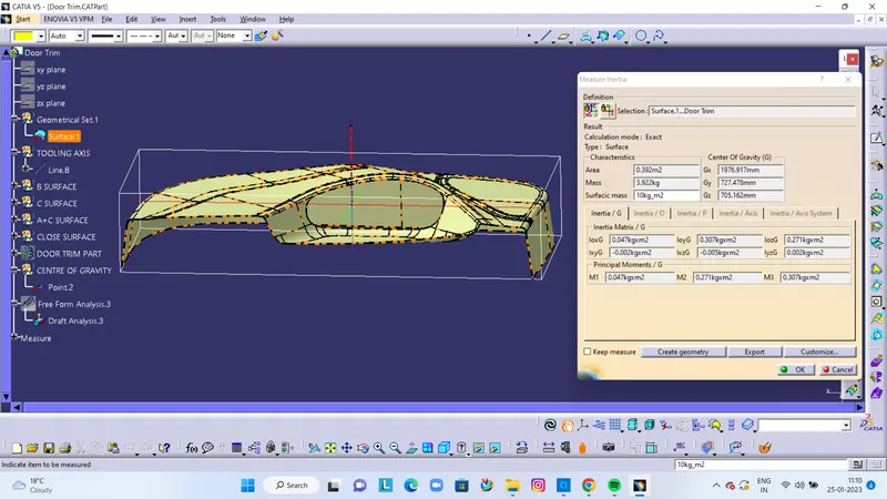
- Using Inertia Method to find out the Center of Gravity and create a line along it.
PROCEDURE TO CREATE THE CLASS B SURFACE:
We'll start the procedure by creating an offset for the entire Class A Surface at a distance of 2.5mm as that is the desired thickness for our final plastic component.
As this is a complex surface hence the offset will fail to offset every element according to our necessity. It'll select some sub-elements that belong to the filleted regions by themselves that we have to remove to get the rest of the surface that is offsetted.
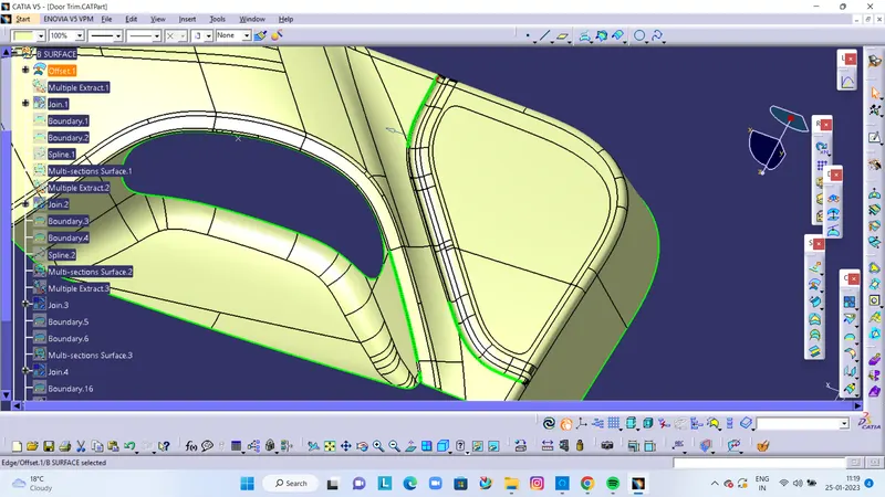
CREATION OF B SURFACE
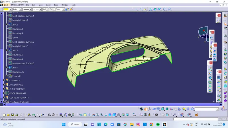
CREATION OF C SURFACE
We'll create the Class C Surface with respect to the Class A Surface and provide draft angles to those surfaces that are parallel to the Main Tooling Axis. Surfaces at the bottom won't be needing any draft angle as they'll get cleared by the core itself. To create the Class C Surface we have to use various commands such as Sweep with Reference Surface and With Draft-Direction depending upon the necessity and at places where it'll be difficult for us to create a surface using Sweep, we'll use Multi-Sections Surface to create those surfaces.
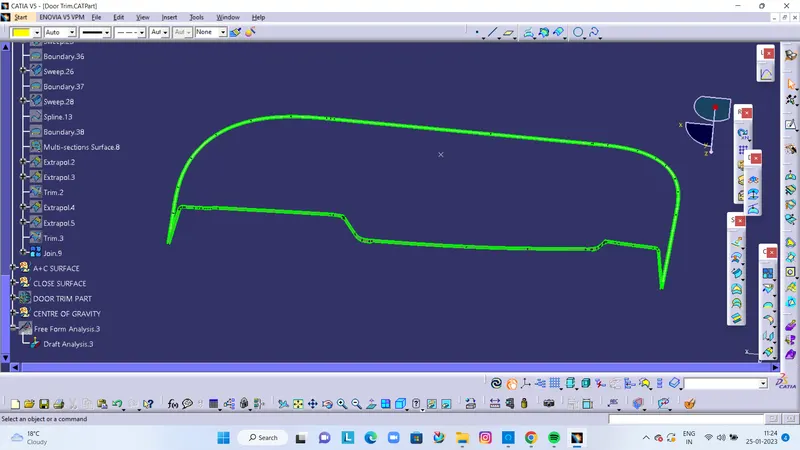
CRAETION OF A+C SURFACE
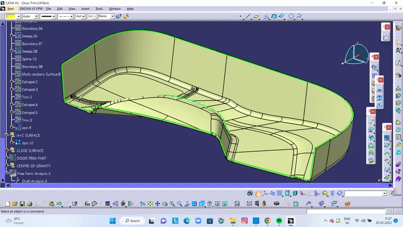
TRIM A+C SURFACE WITH B SURFACE
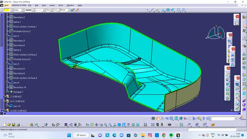
FINAL CLOSE SURFACE DOOR TRIM LOWER
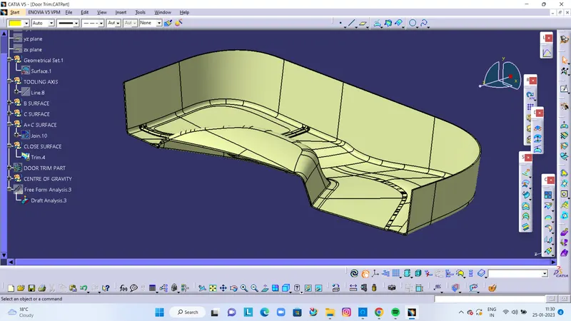
DOOR TRIM LOWER PART DESIGN
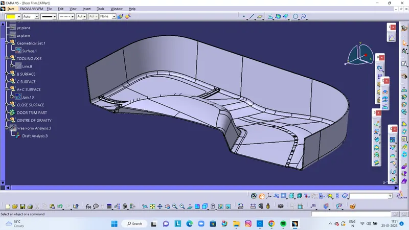
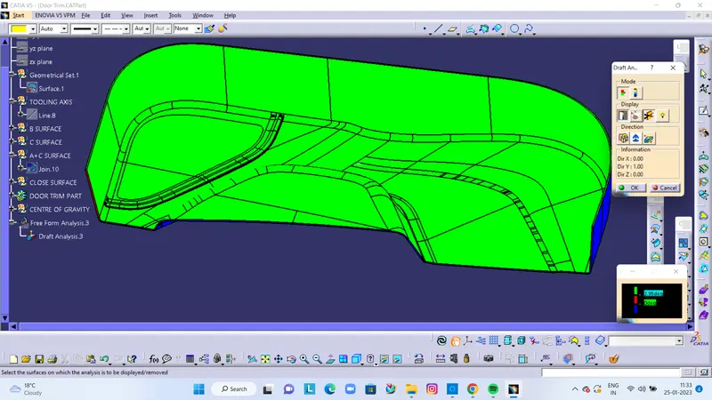
DRAFT ANALYSIS
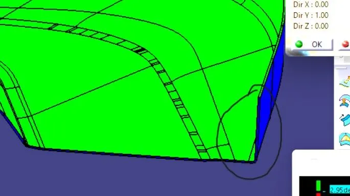
ON CORNER SIDE DRAFT ANALYSIS IS LESS TO 3 DEGREE
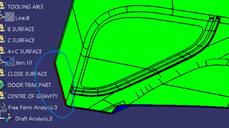
SOME PROBLEM IN CLAAS A DUE TO C SURFACE NOT CREATE PROPERLY.