Week 8 - Challenge 5 - Door Trim Lower
CLASS A SURFACE:
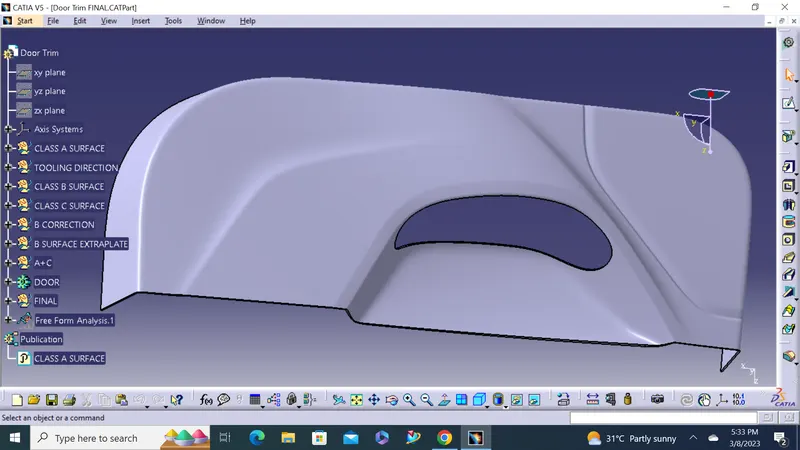
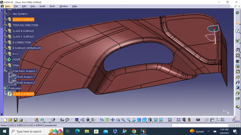
Class A is an aesthetic surface with the highest quality finish. Most Class A Surfaces for an Automotive Component are made using 'Autodesk-Alias' based on the final Concept-Sketch. All Class A surfaces should have 'Curvature-Continuity' which means the continuity between the surfaces should share the same boundary. It is taken as a reference by the Automotive Plastic Designer to create 'Class B' and 'Class C' Surfaces.
TOOLING AXIS:
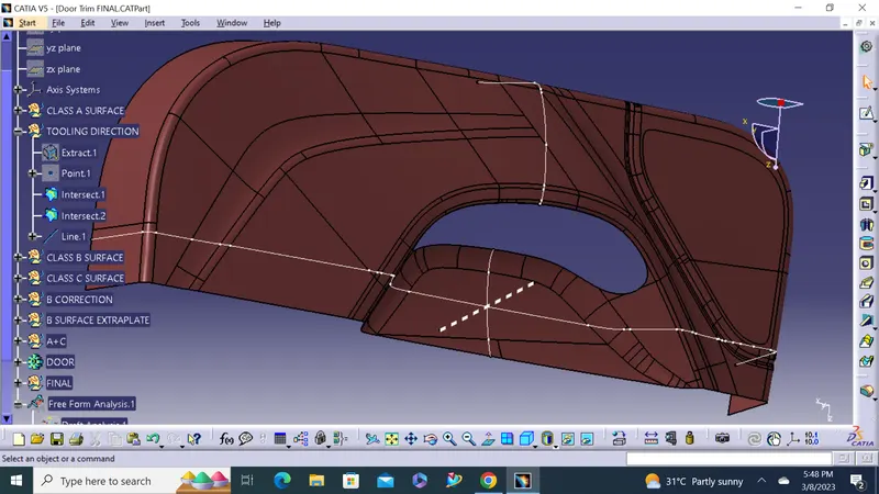
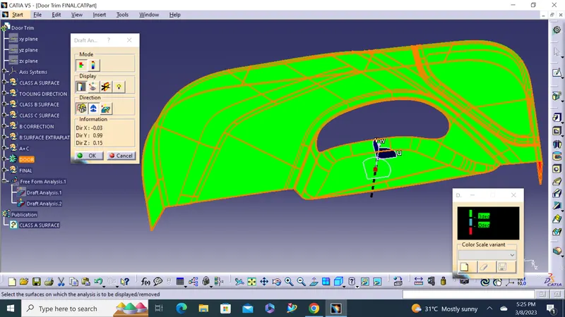
To create the tooling axis, I extracted a surface from class A and created a point in the middle of the surface by using the point command and created a line at that point through the x-axis. Now, I performed a draft analysis check from that line whether the created tooling axis is in the correct position or not. If in the draft, analysis check the surface highlighted with green colour on both sides of the surface the tooling axis is in the correct position and direction.
DRAFT ANALYSIS CLASS A SURFACE:
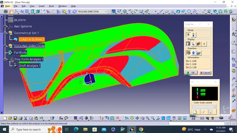
We will perform a Draft Analysis on the Class A Surface itself using the Main Tooling Axis created using the First Method:
Before starting with a Draft Analysis Operation, we will go to the 'Customize View Parameters' option under the 'View Toolbar'. Then we will enter the 'Customize View Mode' where we will go under the 'Mesh' option and select 'Material' and press 'OK'.
To start the Draft Analysis in the 'Generative Surface Design Workbench', we will go to 'Insert' and then look for the option called 'Analysis'. Once found, we will go under that and click on 'Feature Draft Analysis. This will open the 'Draft Analysis' Dialogue box. There, we will ensure that under 'Mode' we have selected 'Quick Analysis', under 'Display' we will select 'Show or Hide the Color Scale' and then select '3 Degrees' as the permissible draft angle. Then, under 'Direction' we will choose the icon with the symbol of the compass on it which stands for 'Use the Compass to define the new current draft direction'.
CLASS B SURFACE:
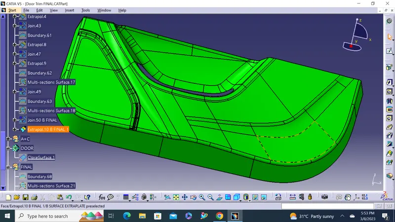
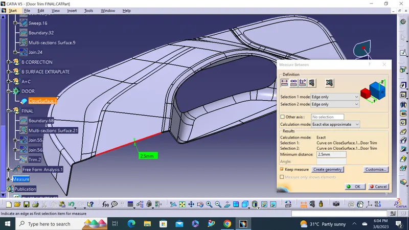
we just offset the Class A surface and get the B surface body here we offeset the 2.5mm value so we get the thickness is 2.5mm is mention in above so we offset the A surface for 2.5mm.
CLASS C SURFACE:
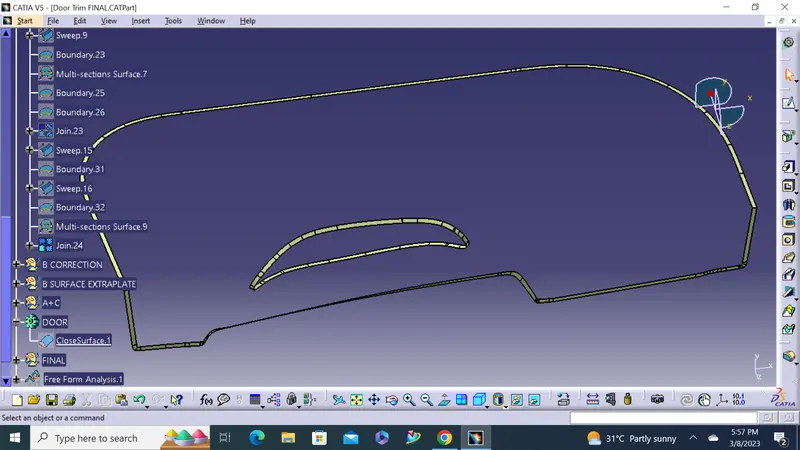
Creating sweep operation based up on A surface edges and critical area surface created by multi-surface operation.
FINAL SURFACE:
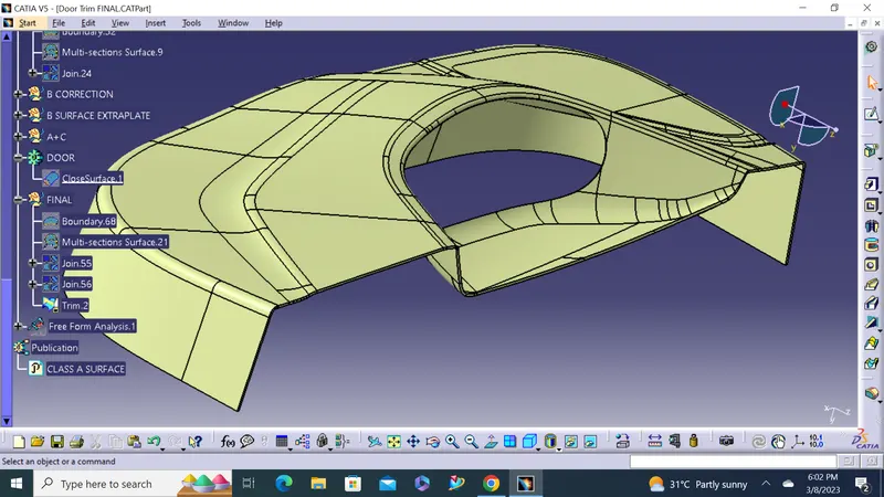
Intially joining A surface and C surface togaether then A+C surface trimming with B surface.
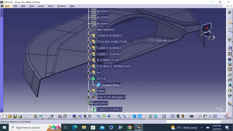
CLOSED SURFACE WITH THICKNESS 2.5 MM:
DRAFT ANALYSIS FINAL SURFACE:
By accounting for thermoplastic shrinkage during the cooling process, draft angles significantly reduce friction between the finished, cooled part and the side of the mould, Not only does this create a much easier release process, but it also offers several other benefits, depending on the design of the part which is as follows:
• Reduces the chance of damage to the part due to friction during the release.
• Reduces wear and tear and chances of damage to the mould.
• Ensures a uniform, smooth, unscratched finish when required. • Ensures the integrity and uniformity of other surface finishes and textures.
• Reduces overall cooling time by lessening or eliminating the need for unconventional ejection setups.
• Most, if not all, of these benefits, offer either direct or indirect overall production cost reductions.
TREE STRUCTURE:
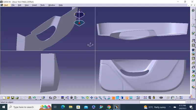
Door Trim Lower views:
Challenge 5 - Door Trim Lower