Week 8 - Challenge 5 - Core & Cavity Design
Aim: To perform the Draft Analysis on the component.
Procedure:
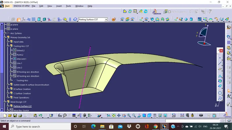
To perform the draft analysis we need to first establish a Tooling Axis.
The tooling axis is created in the following steps.
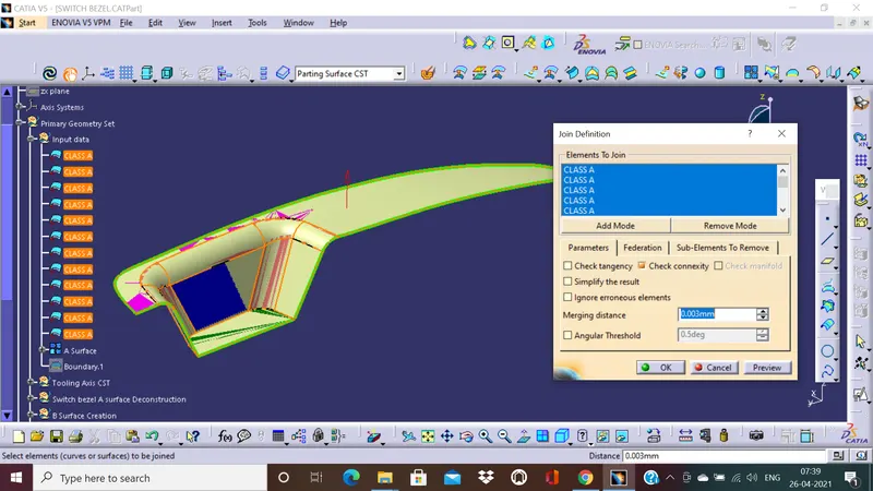
1:We observe the given surfaces and perform the joining operation on surfaces to form one complete Class A surface.
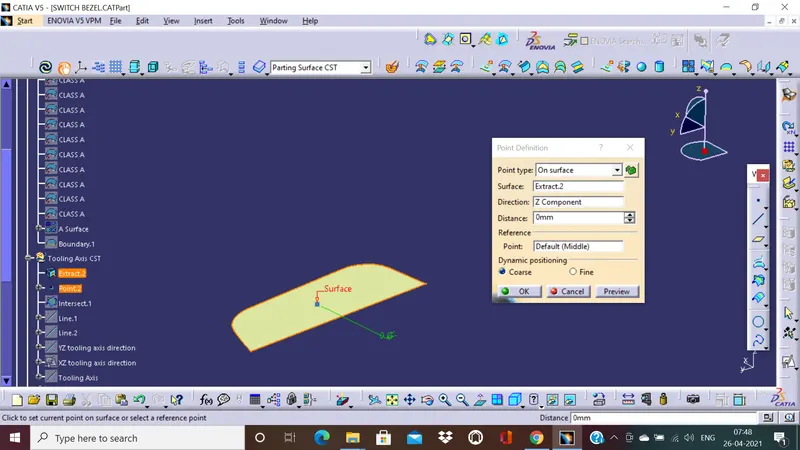
2. We now extract the base surface and create a point at its center. We use this point as the center of our tooling axis because we observe that the Z-axis would be the best tooling direction and the slopes from the bezel are near to parallel to the Z-axis. This would be problematic and need to design our tooling axis carefully on this axis.
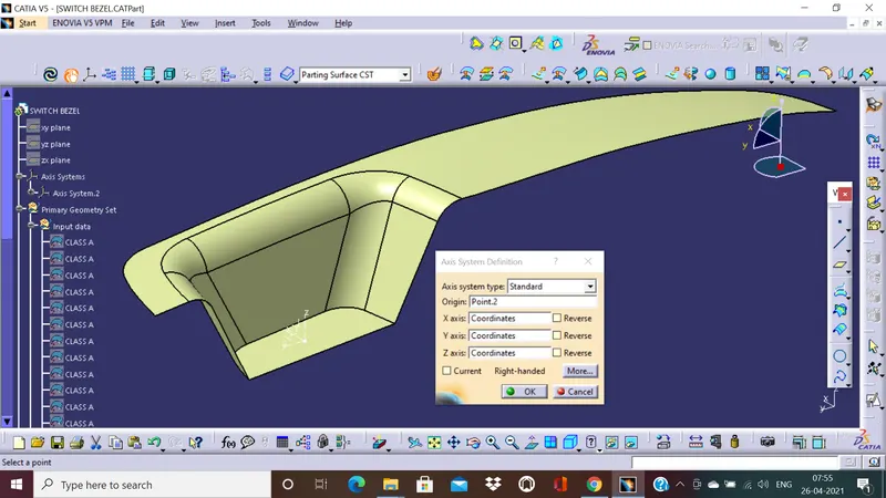
3. We use the created center point to place a new axis system and use the point as the axis origin.
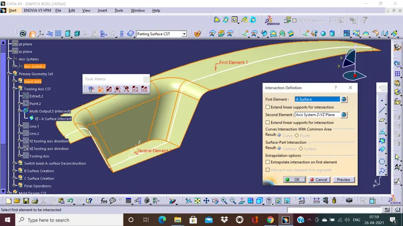
4. Next, we intersect the A surface and YZ plane to form an intersection line and then extend the sloped intersection lines.
5. We can now create and extend the lines that are almost parallel to the Z-axis.
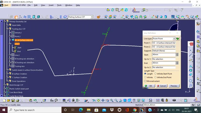
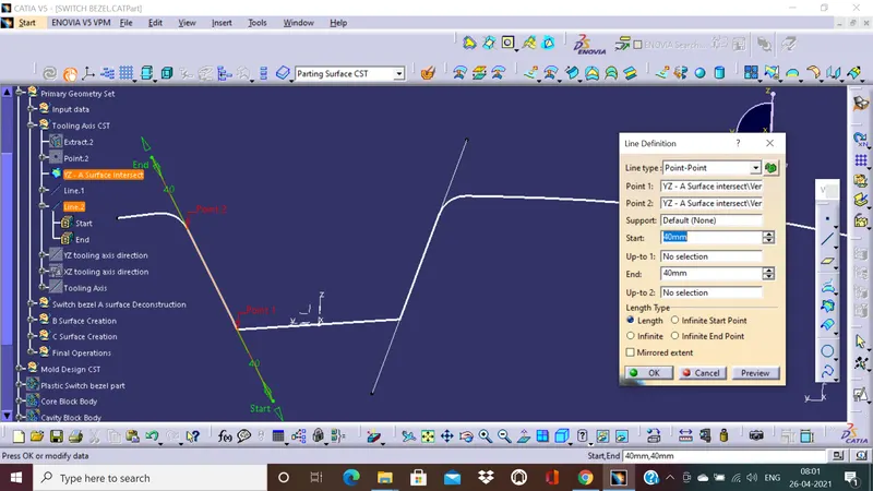
6.It is time to bisect these two lines now. Using the bisect type line, we use Line1, Line2, and the point we created to form the Y direction tooling axis.
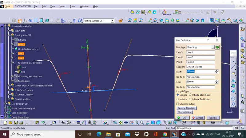
7.The next step is creating the X direction tooling axis. Using the XZ plane and the point for the sketch support, we can intersect the 3D elements onto the plane and make it a reference line. Using the reference intersections, we create a line that is collinear to it and a line that passes through the center point. This line is then angled at 6 degrees from the other line because we observed in our draft analysis that, we are not clearing our minimum draft angle of 3 degrees sufficiently with a value less than 6 degrees.
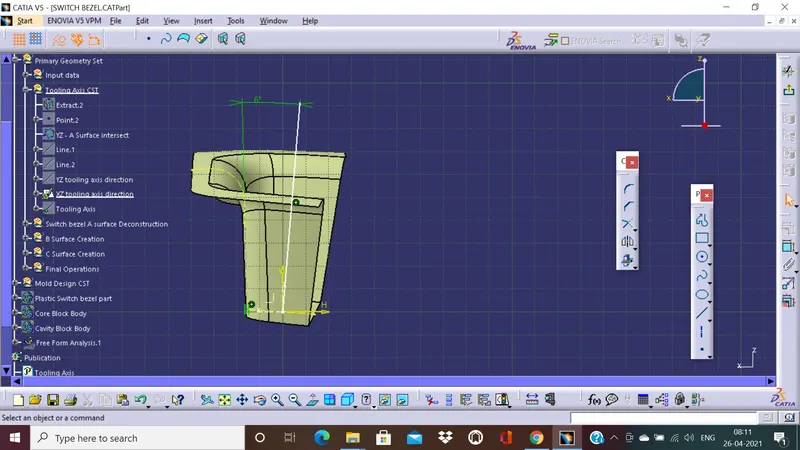
8. Now we are in a position to bisect the two lines, i.e. the Xz direction tooling line and the YZ direction tooling line. We create a line using the bisecting line type. The two lines we created and the center point will provide us the tooling axis we need for manufacturing the part.
Observations:
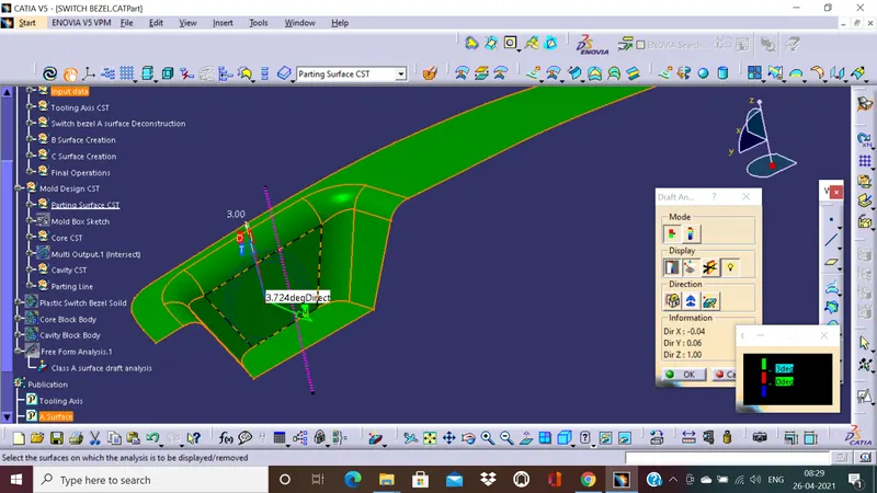
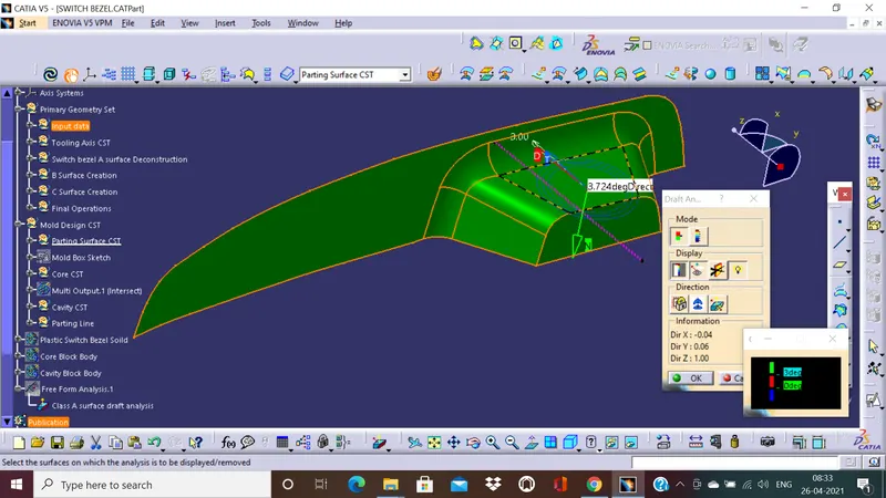
Class A Draft analysis-
Color region codes for draft angle with the tooling axis:
Green: Greater than 3-Degrees
Blue: -3 to +3 Degrees
Red: Less than -3-Degrees
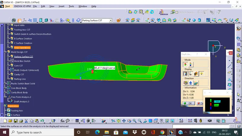
The draft analysis on the A surface is entirely green. This indicates that the class A surface is well designed.
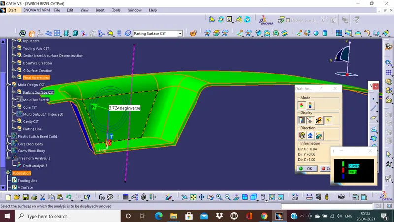
From the draft analysis, we see that the lowest draft angle recorded is 3.72degrees for the steep fall of the part.
Final model draft analysis:
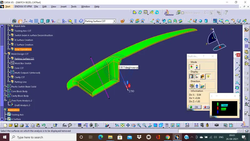
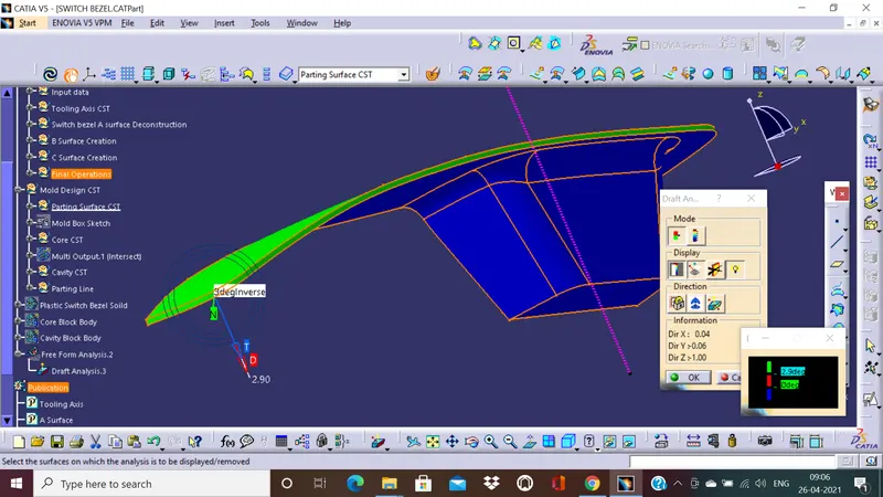
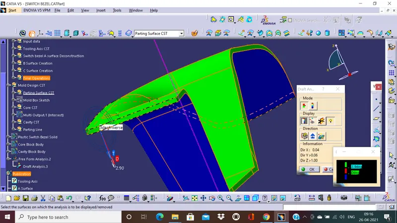
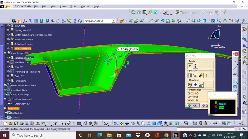
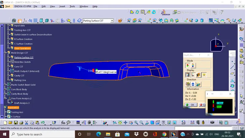
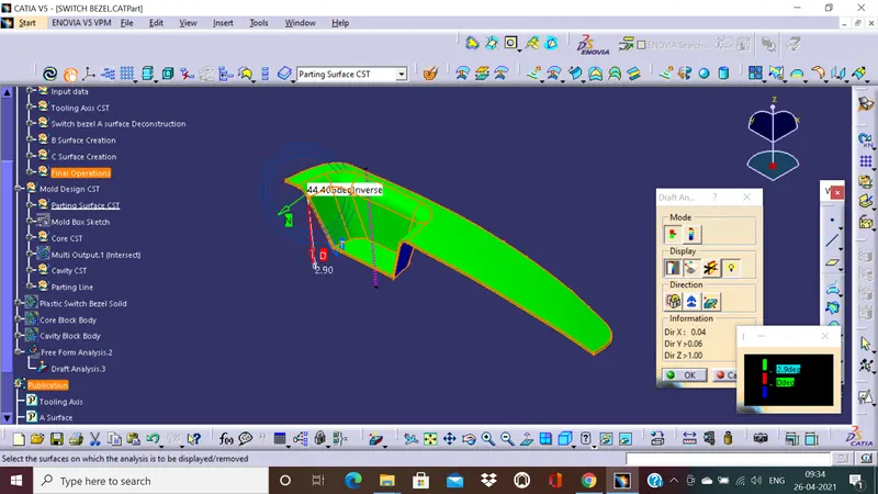
We observe that there is no change in the class A surface but our C surface is having a draft angle range of 2.9 to 3 degrees. We have set our green color range from greater than 2.9 degrees from the tooling axis as it would be acceptable in the industry.
Orientations of the model during draft analysis:
Side views:
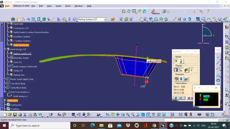
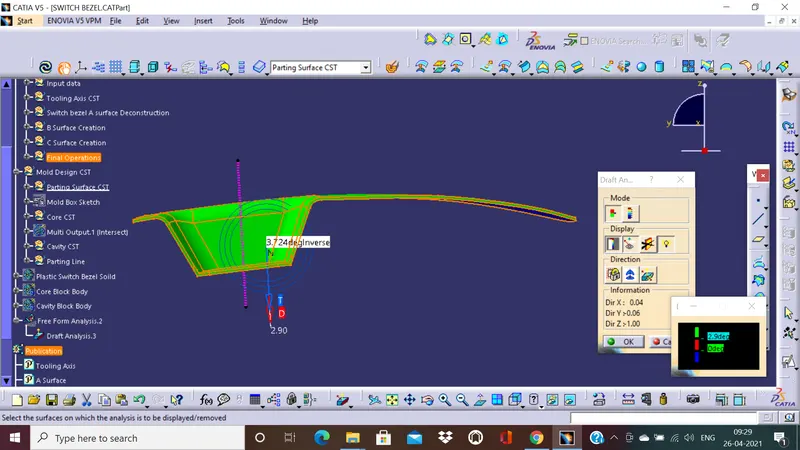
Front views:
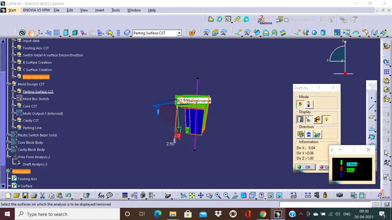
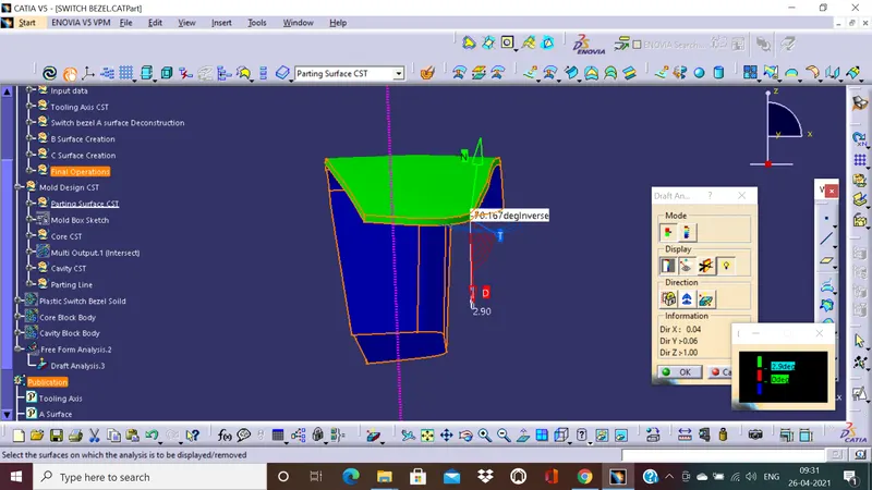
Top views:
Isometric view:
Conclusion:
The region of the lowest draft angles is at 2.95 degrees from the tooling axis. This is an acceptable value and we can conclude that,
the part can be molded using injection molding techniques from the tooling axis.
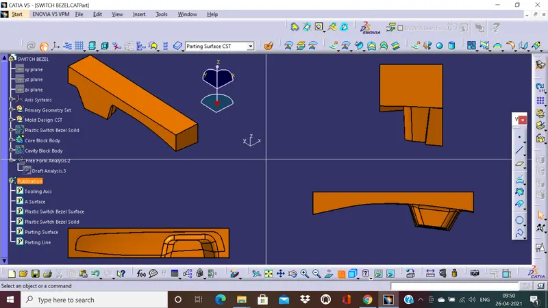
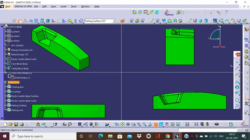
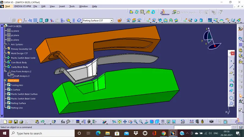
Core block views:
Q1:Front view
Q2:Isometric view
Q3:Bottom view
Q4:Side view
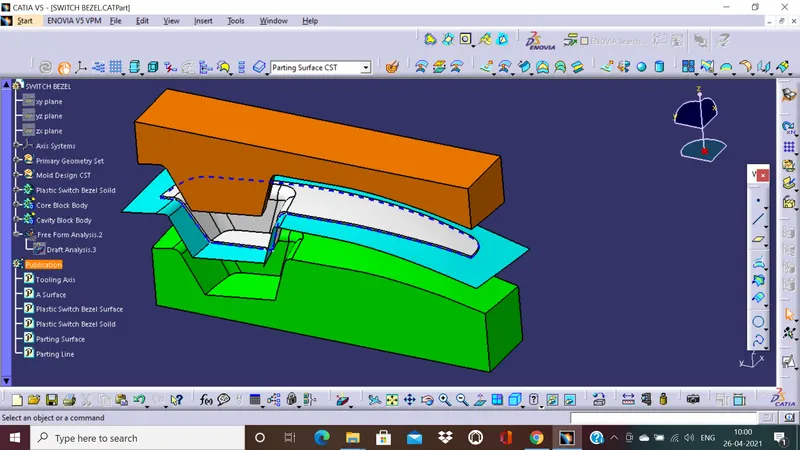
Cavity block views:
Q1:Front view
Q2:Isometric view
Q3:Top view
Q4:Side view
Please see the cat Part in the zipped file. Thank you.