Week 8 - Challenge 5 - Core & Cavity Design
CORE AND CAVITY
AIM :
TO create the core and the cavity for the mould plastic component by using CATIA V5.
PROCEDURE :
- CORE :
The core is the male portion of the mould which create the internal shape of the component. The core side is also called the projection side.
2.CAVITY :
The cavity is the female portion of the mould which create the external shape of the component. The cavity side is also called the depression side.
PARTING SURFACE :
It is known as the splitting surface of the core and the cavity. The two halve of the core and the cavity during injection moulding are pressed tightly and seals to avoid the mould flow leakage and maintain a certain pressure is called the parting surface.
PARTING LINE :
The parting line is an area in which the parting surface and the component will meet. otherwise, it is called the core and the cavity junction.
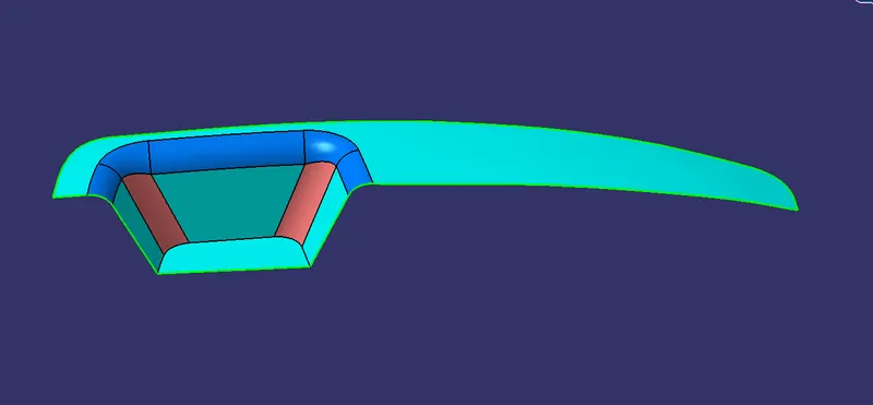
FIG 1.1 PROJECTION SIDE
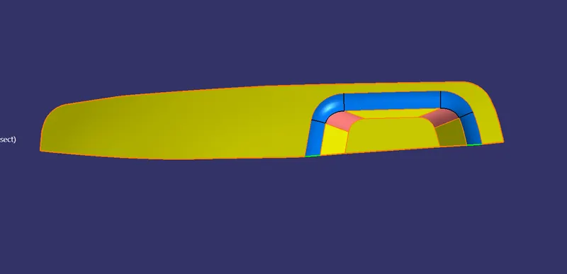
FIG 1.2 DEPRESSION SIDE
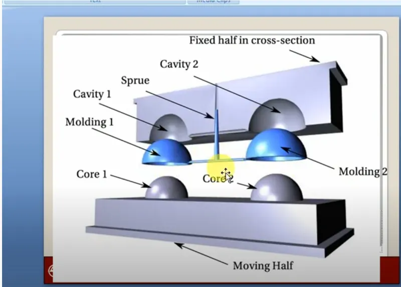
FIG 1.3 CORE AND CAVITY
- To create the core and the cavity the initial step is to create the parting surface.
- The first step is to create the geometrical set.
- After creating the set the boundary has to create from class A.
- The next step is to extrapol the class A SURFACE.
- After extrapol the A Surface the extended A surface have to trim with that class C surface.
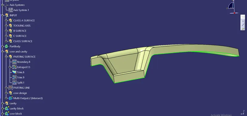
The next step is to unhide the class B surface, the extended B surface is trim with the CLASS A and C surface.
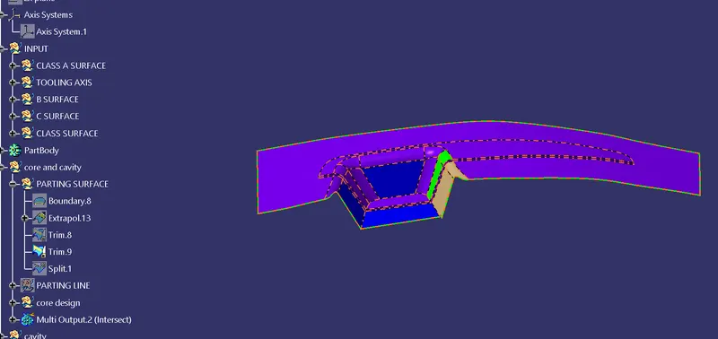
FIG 1.4 CORE CLEARING FACES
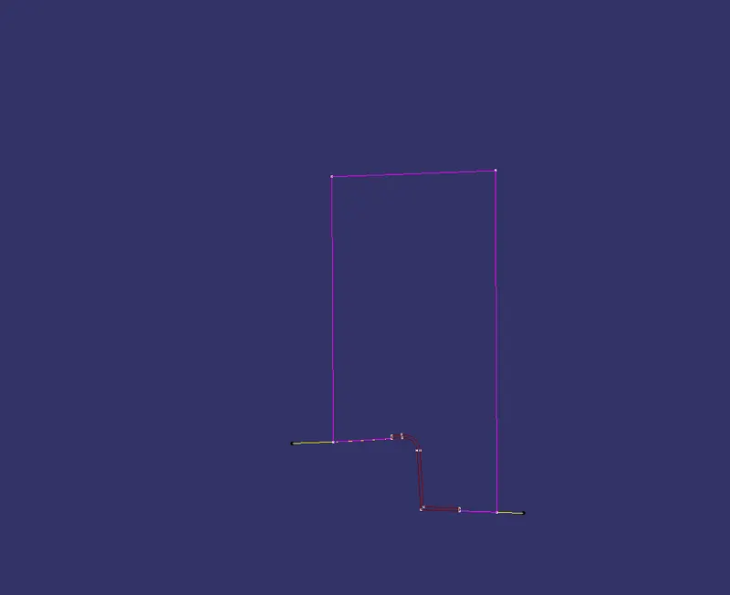
FIG 1.5 INTERSECTION
The above diagram shows the core and class surface intersection.
The pink line shows the core intersection line.
The red line shows the Class Surface.
The core line is created in B surface the A surface is not core is created.
CORE DESIGN :
- After creating the parting surface the next is to create the core surface.
- Insert geo set in the switch bezel and then create a sketch with constrain.
- After constrain extrude the sketch with respect to the tooling axis.
- Then remove the unwanted portion and the core part is created.
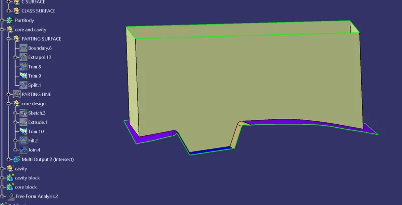
FIG 1.5 CORE PART
- The above step is done and then the top is filled with the fill command.
- After fill the command joins the trim and fill in the command.
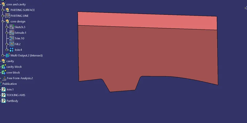
FIG 1.6 CORE
CAVITY DESIGN :
Extrude the same portion with the constrain sketch.
The same procedure is followed to create the cavity part.
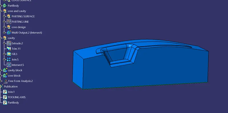
FIG 1.7 CAVITY PART
The cavity part is created.
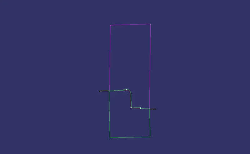
FIG 1.8 INTERSECTION OF CORE AND CAVITY
The above pic it shows the core and the cavity of the surface.
PARTING SURFACE:
For the parting surface, we have to split the class b surface with the intersection line of the parting line.
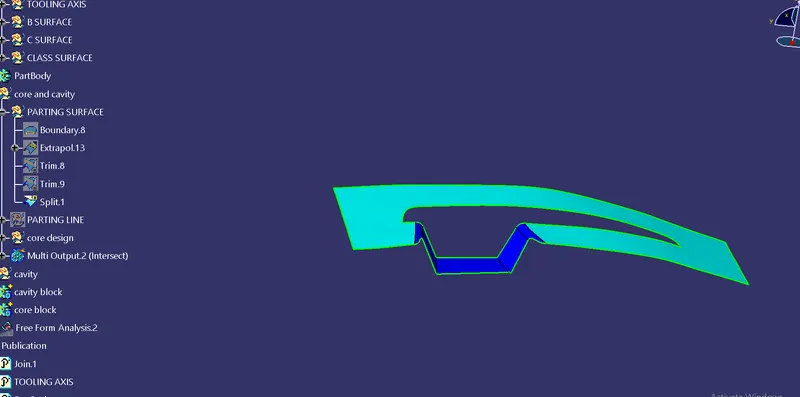
FIG 1.9 PARTING SURFACE
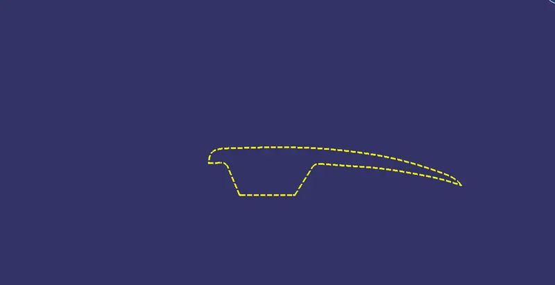
FIG 1.10 PARTING LINE
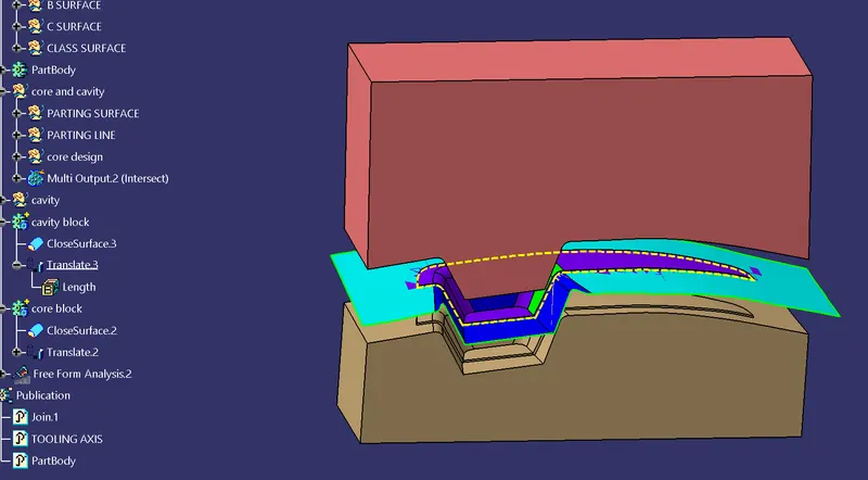
FIG 1.11 CORE AND CAVITY
RESULT
Then the core and cavity are achieved with the help of the CATIA.