Week 8 - Challenge 3 - Switch Bezel Design
SWITCH BEZEL DESIGN
1.AIM :
To create the switch bezel plastic component through the given Class-A Surface by using CATIA.
2.Procedure:
- CLASS A SURFACE :
The class a surface is an initial process to bring the plastic component design from scratch to mass production. The class a surface it has no thickness. The Class A surface is used for the aesthetic surface of a product. From Class A surface the solid model is created.
Procedure for Class A:
- The initial step is to import the catia file from the sketch designer.
- After importing the file the first step is to ensure that the Class A surface is connected. It can be ensured in two methods.
- By using the join command
- By using boundary command.
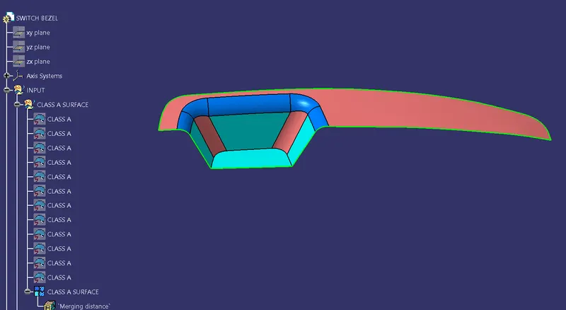
FIG 1.1 CLASS A SURFACE
The above picture will ensure that the Class A Surface is connected.
B. TOOLING AXIS :
The tooling axis is a direction to open the mold open or close or the cavity and the core to open and close. The tooling axis is used to create the draft analysis. Most of the designers will choose the hole in the surface or the flat surface to choose as a tooling axis point. The choosing plane in the tooling axis point main criteria is to clear all the faces on the surface. The tooling axis is to create because the parallel faces in the surface which make trouble in the drafting to avoid the intersecting lines have been creating.
PROCEDURE FOR TOOLING AXIS :
The first step in the tooling axis is to whether the hole or the flat surface is to choose for the tooling axis.
In the part, the holes are not in there to create axis points. So we have to make it a flat surface.
After choosing the flat surface the X, Y, Z which direction meet all the faces have to check.
In this part, the Z direction gives all the faces of the diagram.
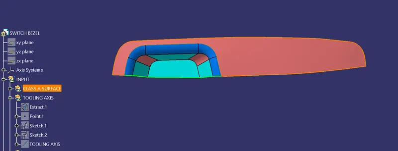
FIG 1.2 Z DIRECTION FOR TOOLING
- The flat face of the A surface has chosen the point have to fix for the tooling axis.
- The above dia shows that the YZ direction has two parallel faces and the z x-direction has one parallel face.
- The next step is to create the bisecting line by using a position sketch.
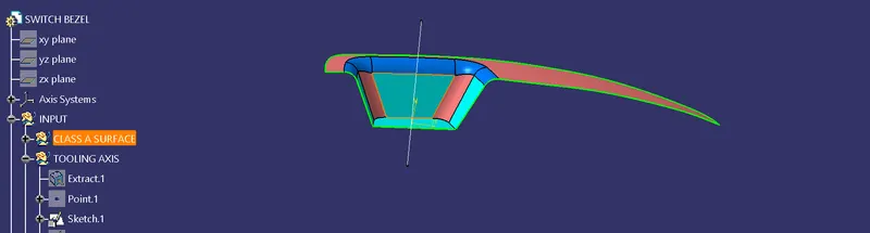
FIG 1.3 BISECTING LINE FOR ZY DIRECTION
- The next step is to create the bisecting line for the ZX direction.
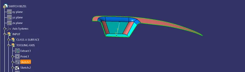
FIG 1.4 BISECTING LINE FOR ZX DIRECTION
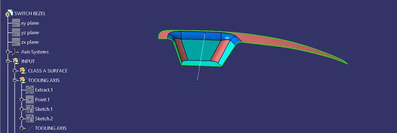
FIG 1.5 TOOLING AXIS LINE
- With the two-axis line, the bisecting line has to been created for the TOOLING AXIS in the point direction.
- We have to check by clicking the line in the tooling axis line and the normal view icon it shows the created tooling axis which shows all the faces.
CLASS B SURFACE :
The B surface is created by thickening the A surface. The A surface has no thickness.The B Surface which is for the Engineering purpose. To thicken the A surface.
PROCEDURE FOR B SURFACE :
- To create the B surface the A surface has to extract and been offset the surface.
- The rest arm of the surface is to extract from the A surface and then untrim the face and the expolrate.
- By doing the same procedure the Walls of the A surface have to be done.
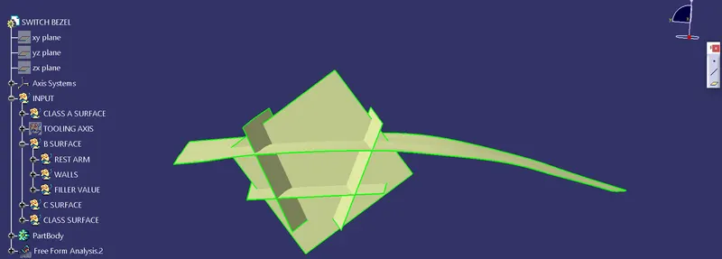
FIG 1.6 EXTRAPOL OF A surface
- After extrapolate according to the A surface, it has to be trim.
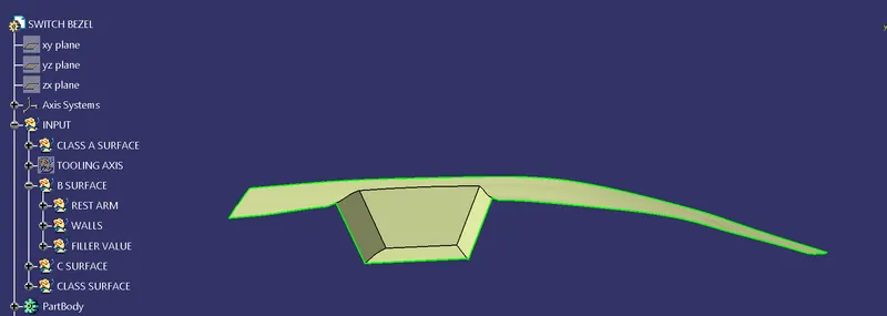
FIG 1.7 B SURFACE
- Then unhide the A surface and then offset the B surface according to the given thickness of 2.5mm.
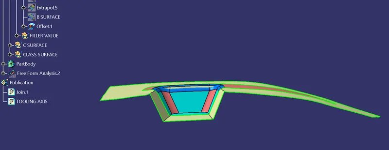
FIG 1.8 Offset B surface
After offsetting the B surface we have to give the wall thickness
UNEVEN WALL THICKNESS.
- When the wall thickness for a surface is not even to it may cause a defect in the flow line. when the thickness is not even it may cause the flow streak and then make bend inside the mold tool and some other defect will happen.
- To avoid the wall thickness have to be made equal.
To avoid uneven the fillet radius has to be measure and then the fillet has to given to the B surface.
By giving the fillet when an offset is made outside the fillet will give in the option.
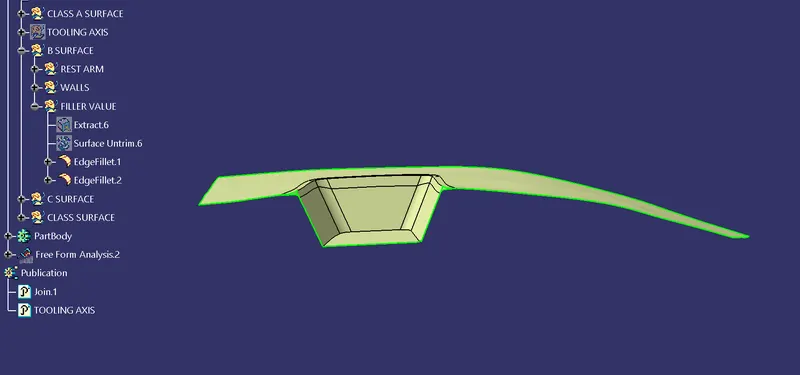
FIG 1.9 WALL EVEN THICKNESS
The next wall thickness which has to be given for an outside fillet the value should be given the difference between the fillet and the offset to make equal wall thickness.
CLASS C SURFACE
The class c surface is to create join the A surface and the B surface.
Procedure for C surface :
- The procedure for the C SURFACE is to create multiple extracts or the boundary of the outer surface from Class A.
- For the above-given surface the A surface boundary has extract from the A surface and then make a smooth curve.
- After making a smooth curve we have to go to sweep command then the draft direction has to give at an angle of 3deg.
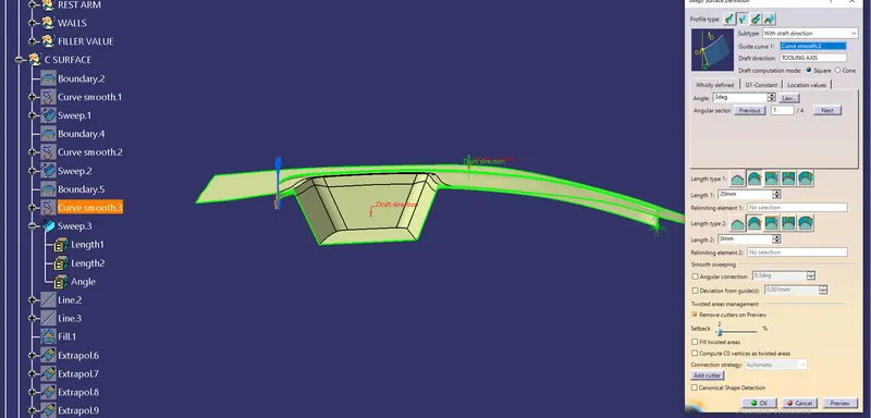
FIG 1.10 SWEEP COMMAND
Fig 1.10 explains the command to give sweep.
Then the C surface is created with the help of the sweep command .
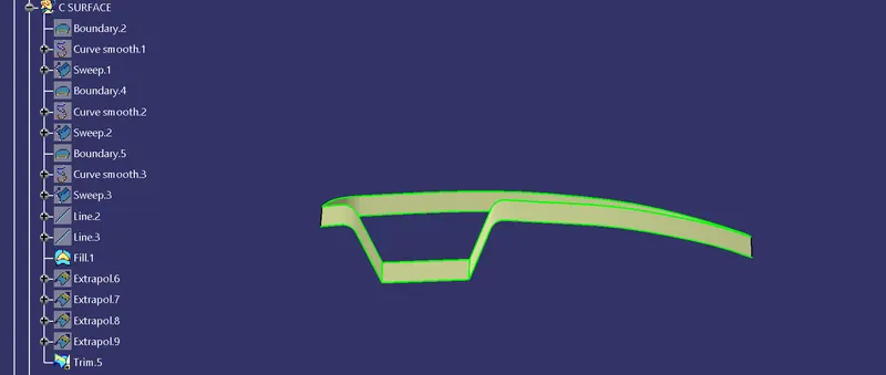
FIG 1.11 CLASS C SURFACE
FINAL TRIM :
After creating the CLASS A B C surface the final trim process is to be taken to complete the process.
The first step is to join the CLASS A surface and the CALSS C surface.
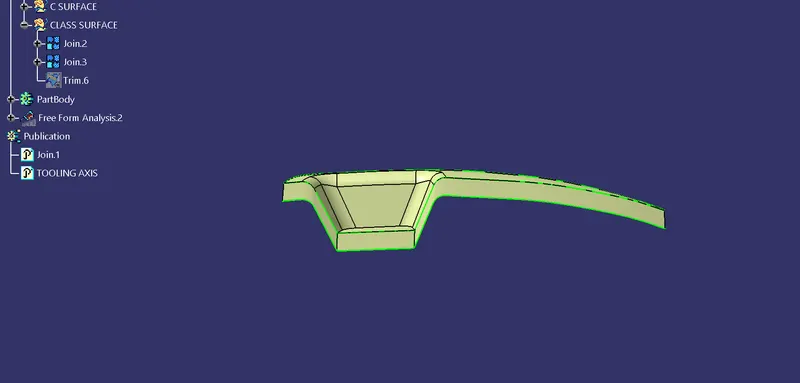
FIG 1.12 JOIN SURFACE
Then the final step is to trim the joint surface with the Class B surface.
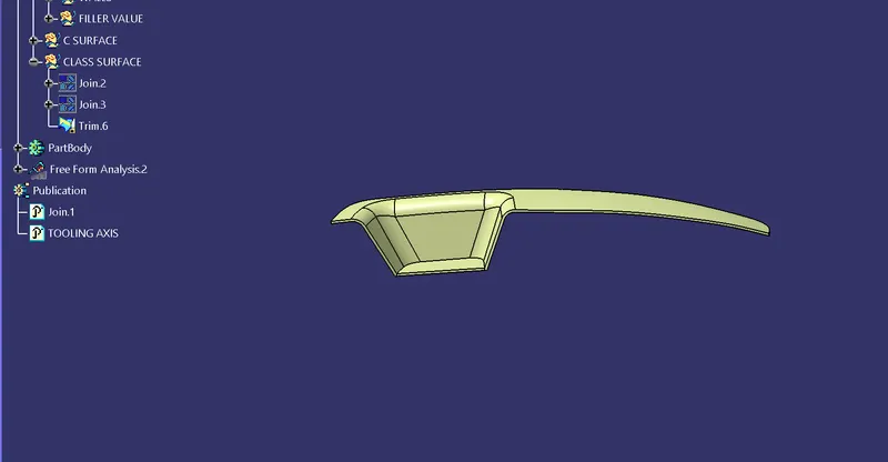
FIG 1.13 FINAL OUTPUT
DRAFTING ANALYSIS
Drafting analysis is used to make the product in taper or minimum angle to avoid the damage of the product. when the product is on a flat surface it may make wear and tear and to avoid friction shrink and use for the ease ejection.
PROCEDURE
- From the tool command, the analysis it has to choose then the draft analysis is to be done.
- The draft analysis dialog box will display on the screen
- The first step is to use the compass and lock the compass in the tooling axis which we created.
- Then use the lock icon to lock the compass
- Then with the help of the running point check the angle of the component is below r above 3 deg.
-
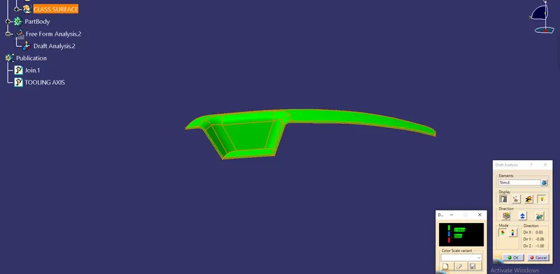
FIG 1.14 DRAFT ANALYSIS
After doing a draft analysis then the solid part is made by closing the surface icon.
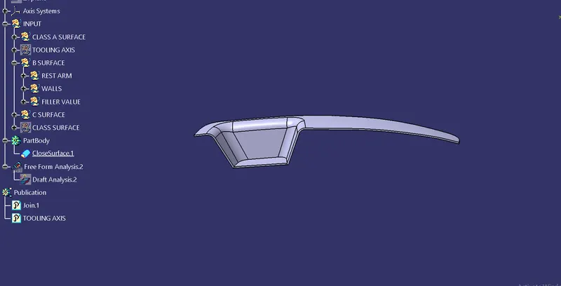
FIG 1.15 FINAL OUTPUT
PUBLICATION
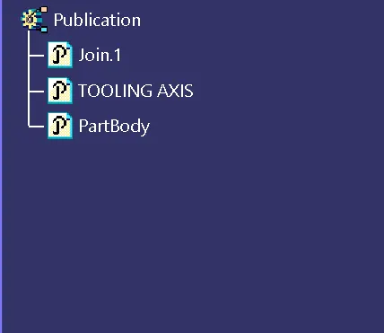
fig 1.16 publication
RESULT
THE SWITCH BEZEL is achieved on basis of the mold processing standards.