Week 8 - Challenge 4 - Coin Holder Design
COIN HOLDER
AIM :
To create the Coin Holder plastic component through the given Class-A Surface by using CATIA.
2. PROCEDURE:
- CLASS A SURFACE :
The class a surface is an initial process to bring the plastic component design from scratch to mass production. The class a surface it has no thickness. The Class A surface is used for the aesthetic surface of a product. From Class A surface the solid model is created.
Procedure for Class A:
- The initial step is to import the catia file from the sketch designer.
- After importing the file the first step is to ensure that the Class A surface is connected. It can be ensured in two methods.
1. By using the join command
2. By using boundary command.
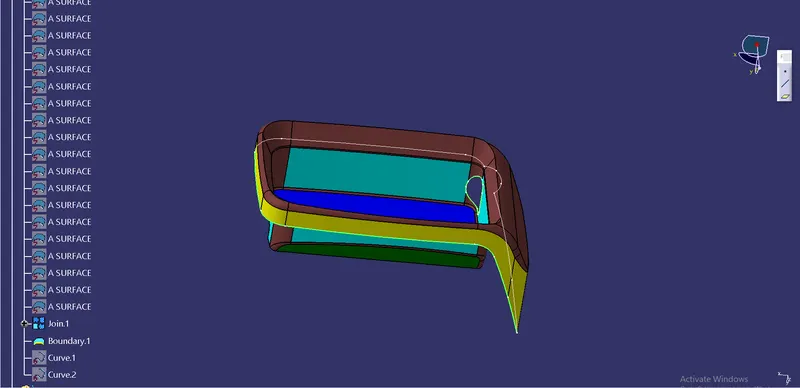
FIG 1.1 CLASS A SURFACE
- The above picture will ensure that the Class A Surface is connected
B. TOOLING AXIS :
The tooling axis is a direction to open the mold open or close or the cavity and the core to open and close. The tooling axis is used to create the draft analysis. Most of the designers will choose the hole in the surface or the flat surface to choose as a tooling axis point. The choosing plane in the tooling axis point main criteria is to clear all the faces on the surface. The tooling axis is to create because the parallel faces in the surface make trouble in the drafting to avoid the intersecting lines.
PROCEDURE FOR TOOLING AXIS :
- The tooling axis's first step is to whether the hole or the flat surface is to choose for the tooling axis.
- In the part, the holes are not in there to create axis points. So we have to make it a flat surface.
- After choosing the flat surface the X, Y, Z which direction meet all the faces have to check.
- In this part, the Y direction gives all the faces of the diagram.
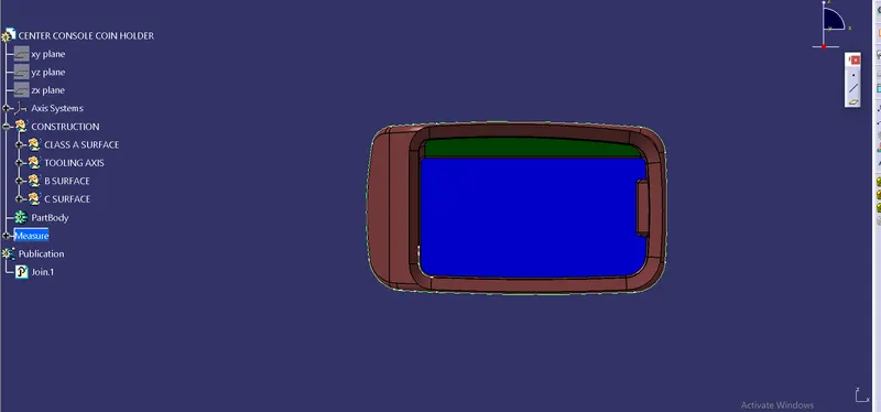
FIG 1.2 Y DIRECTION FOR TOOLING
- The flat face of the A surface has chosen the point have to fix for the tooling axis.
- After choosing the flat face we have to extract the face which we choosen.
- Then in the point definition on the surface is chosen, the point in the extracted face is created.
- Then the next step is to create the intersection for the tooling axis to clear the parallel face.
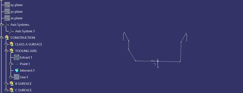
FIG 1.3 INTERSECTION
- By seeing the intersect line it has a parallel face but it has a straight line the parallel has to be an angle of at least 3 deg to clear the draft analysis.
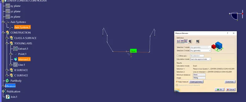
FIG 1.4 MEASURE BETWEEN AXIS AND INTERSECT
The above diagram clearly shows that the angle is 90 deg.
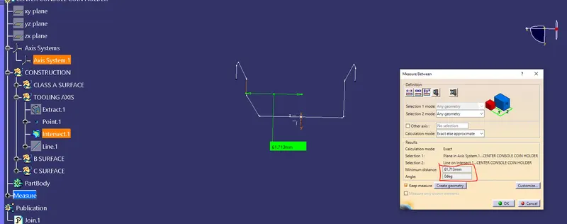
FIG 1.5 MEASUREMENT FOR PARALLEL FACE
- The above pic clearly shows that it has an angle is 0deg. Min, it has to be 3 deg for drafting . The problem is in the CLASS A surface itself.
- It's difficult to rectify Class A surface by a surface developer.
- So the drafting analysis is not done for this part.
- In this a case, the tooling axis is created on the flat surface in a straight line.
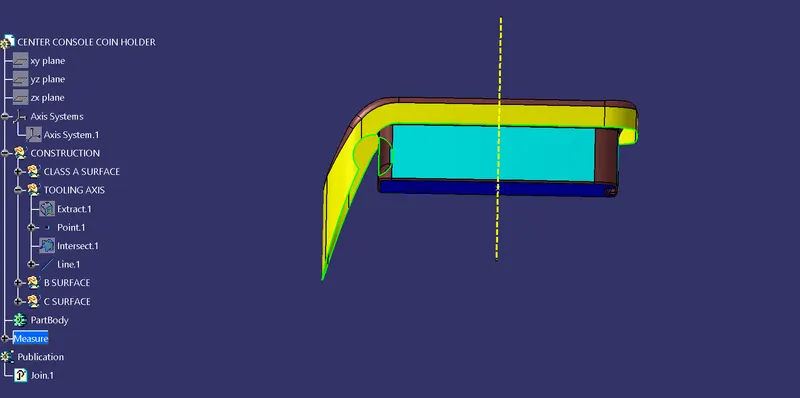
FIG 1.6 TOOLING AXIS
C. CLASS B SURFACE :
The B surface is created by thickening the A surface. The A surface has no thickness. The B Surface which is for the Engineering purpose. To thicken the A surface.
PROCEDURE FOR B SURFACE :
- To create the B surface the A surface has to extract and been offset the surface.
- The sidewalls of the surface area to extract from the A surface and then untrim the face and the expolrate.
- By doing the same procedure the other portions ate to be offset from the A surface have to be done.
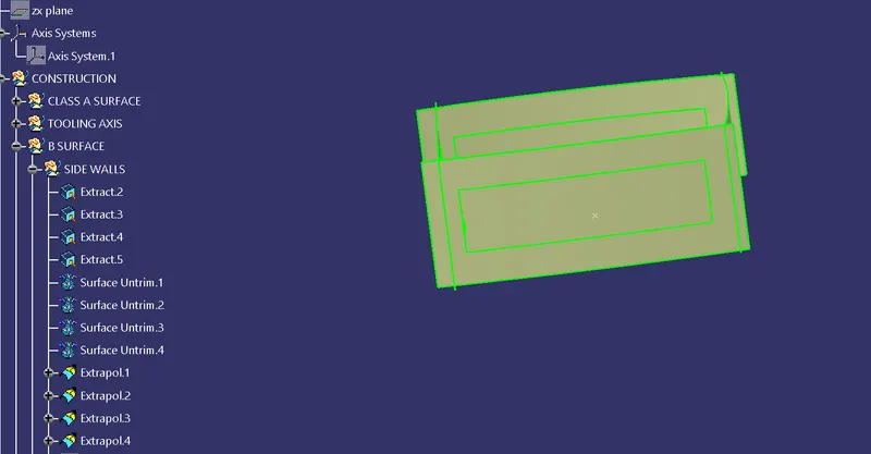
FIG 1.7 SIDEWALLS EXTAPOL
And then next step is to trim the unwanted portion and then offset the trim portion for 2.5 mm in outside of the CLASS A SURFACE.
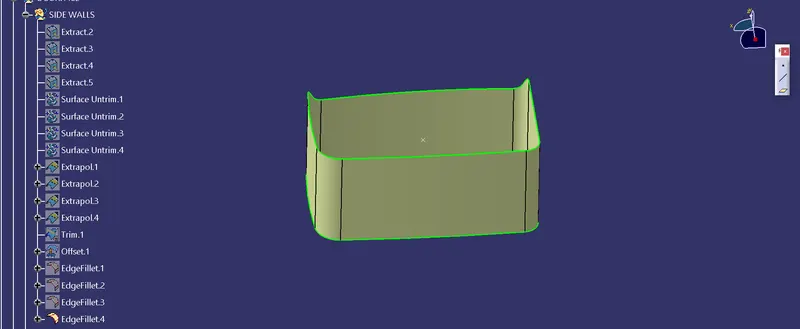
FIG 1.8 FILLET PORTION
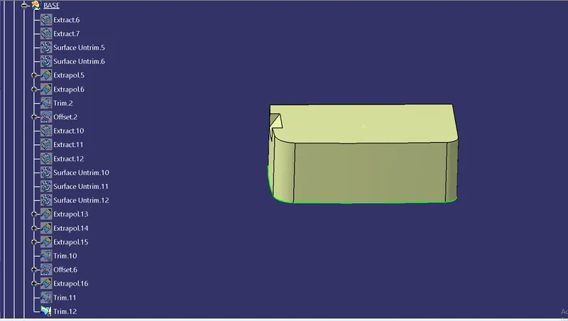
FIG 1.9 BASE & SIDEWALL ATTACHED
The above pic shows the base and the walls are trimmed and then offset for 2.5 mm.
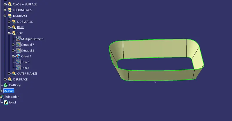
FIG 1.10 TOP WALL
The next step is to top the wall which is extrapol and trimmed with the other two features.
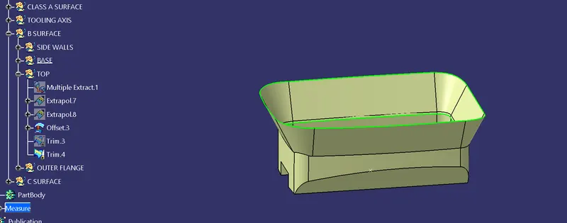
FIG 1.11 TRIMMED B SURFACE
OUTER FLANGE :
The next surface is the outer flange which has to be offset for the B surface
The above class B surface has offsetted in the outer side of the Class A Surface. Now the outer flange has to be offset inside the Class A
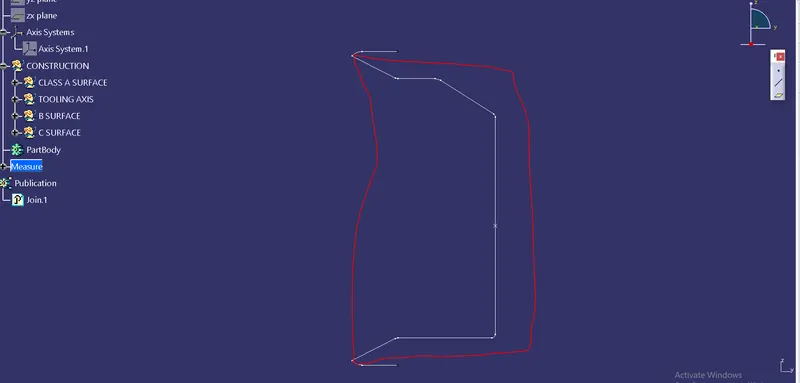
The above dia it shows the red mark which has to be offset outside. the remaining portion which is to be offset inside of class A to close the surface with the help of the class C surface.
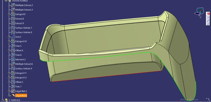
FIG 1.11 CLASS B SURFACE
CLASS C SURFACE
The class c surface is to create join the A surface and the B surface.
Procedure for C surface :
- For the coin holder in the sweep option, the draft analysis is not suitable due to the draft analysis is not done.
- The next method is introduced in the method.
- The Class A surface boundary which is to extract
- Then the BOUNDARY is extact the elements to extract for the sweep command.
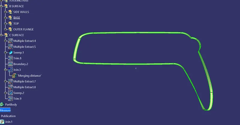
FIG 1.12 SWEEP
The sweep command has to give inside for the 90deg create and the boundary which is to class A and the cLASS B which is to close.
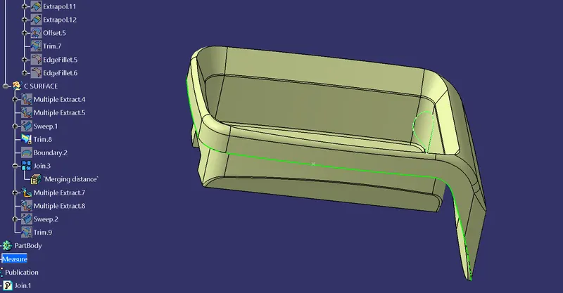
FIG 1.13 Final output
After creating a C surface it has to join with the Class A SURFACE.
After joining the A surface it has to trim with the B surface.
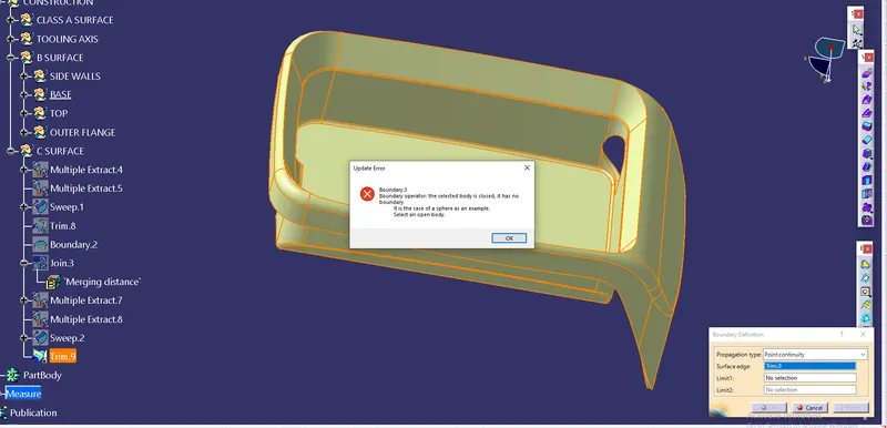
FIG 1.14 BOUNDARY CHECKING
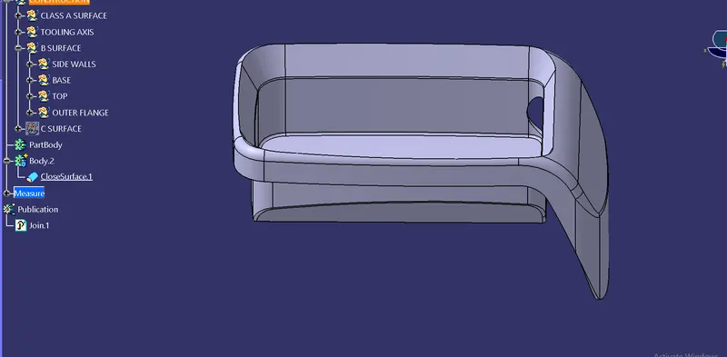
FIG 1.15 CLOSED SURFACE
TREE STRUCTURE :
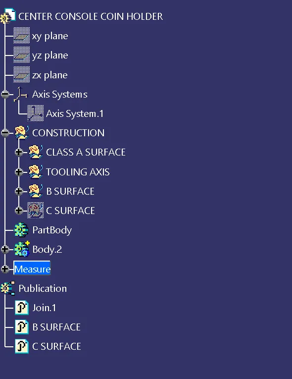
FIG 1.16 TREE STRUCTURE
RESULT
THE COIN HOLDER is achieved on basis of the mold processing standards.