Week 9 - Attachment Feature Creation - Challenge 1
Aim: Create the rib for the Centre console coin holder considering the design rules mentioned in the video.
Introduction: Plastic parts design is a very complex process and it requires the involvement of many factors like functional requirements, process constraints, material selection, and assembly or structural issues. Wall thickness, Draft, Textures, Ribs & Bosses, Holes/Depressions, etc. are some of the important elements to be considered in the design of plastic parts. Adhering to these basic design guidelines for injection molded parts can improve the moldability of the designs and the life of the mold, increase the operational life of the part and reduce manufacturing costs.
Ribs :
Ribs are a feature in plastic injection molded parts. They are thin extensions that run perpendicular to a wall or plane. They are commonly used to provide additional support and strength to a part.
Thickness and location are essential to rib design. Here are some helpful design guidelines:
- They should be designed with a thickness that is ½ the wall thickness to avoid a thick section at the wall base
- To minimize sink marks, design ribs that are approximately 60% of the joining wall thickness for minimum risk
- Best practices include spacing at a distance of at least twice the wall thickness
- Glossy materials require a thinner rib (40% of wall thickness)
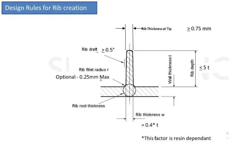
An advantage of using ribs is that they increase the strength of the part without increasing wall thickness. Walls that are too thick can sink, warp or result in other defects. Their integration into a part results in less material usage; therefore a more cost-effective solution.
Procedure :
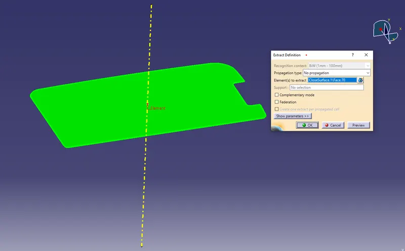
- Since we have the coin holder, rib creation is started with extracting the plane over which the construction will be performed.
- On this plane, the line is drawn that will be then this line is extruded along the direction of the tooling axis to a height of 12.5mm following the design rule of H=5*t.
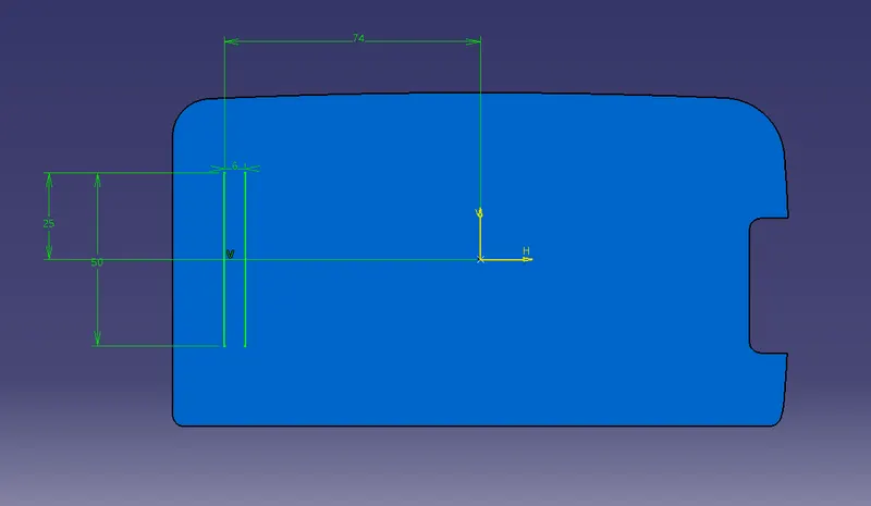
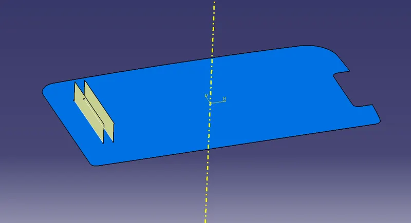
- Afterward, moving to part workbench this line is thickened by 1mm since the rib thickness has to be 0.4*t.
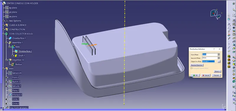
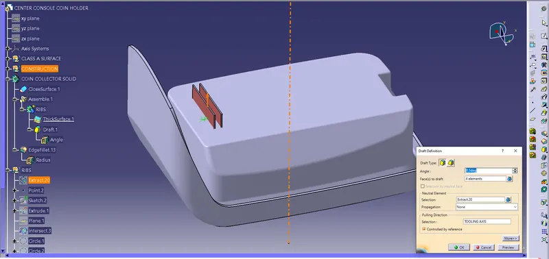
- The thickened ribs later on drafted by 0.5 degrees pulling direction is taken as the upper face of the ribs.
- The drafted rib is then assembled into the coin holder part body. (we can use the add the boolean operation here ).
- Another rib is created at the spacing of 2*t of design rule and assembled to coin holder.
- Lastly, both ribs are provided with fillets of 0.25mm radius.
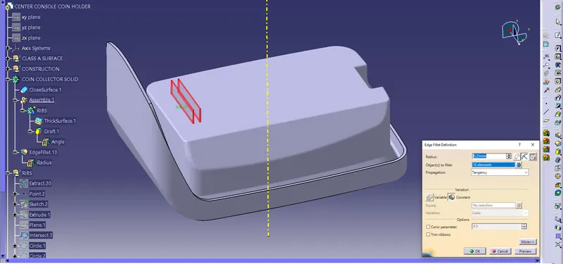
Checking the ribs design :
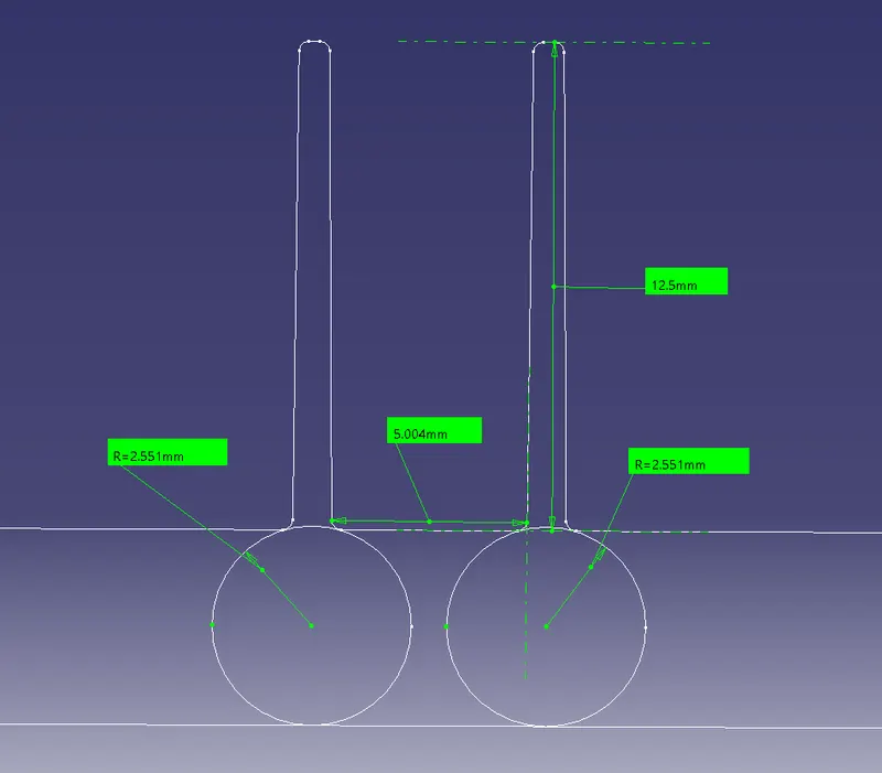
In order to check for the dimensions of the ribs, the coin holder is intersected along the XY plane to obtain the boundary lines.
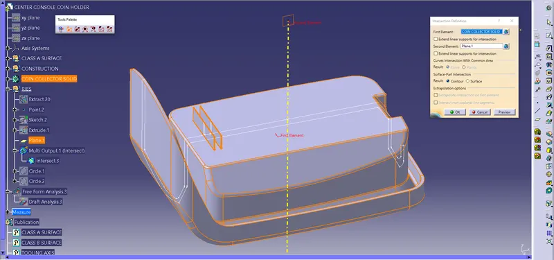
Root analysis :
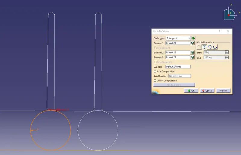
For the root analysis, the circle by tri-tangent from the outlines of ribs and base surface, and then this circle dimension is measured.
Draft analysis :
Now, the ribs need to be checked for the draft analysis to ensure if all the features have passed the tooling direction :
- Open the feature draft analysis from the insert menu.
- Move the compass to align with the tooling axis and then select the component.
- Here, change the minimum drafting angle to 0.5 degrees since the draft provided to ribs is 0.5.
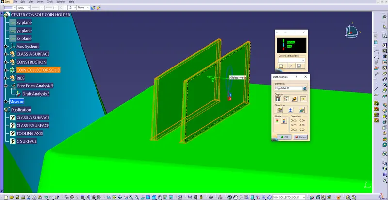
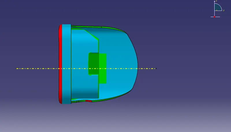
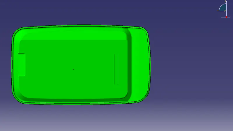
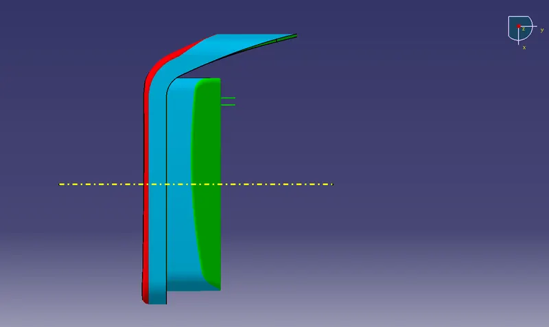
All the features of the ribs show the green line that means the current tooling direction is able to capture all the features of the ribs.
- Screenshots of the completed design in various orientations (Isometric, Front, Side, and Top View)
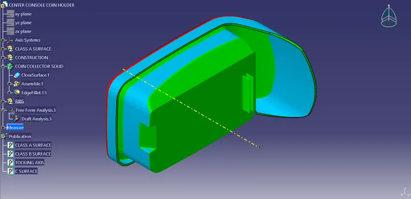
Result: Created the rib for the Centre console coin holder considering the design rules.