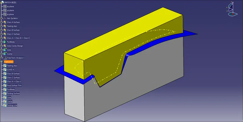
Switch Bezel Design and Core - Cavity Design
Aim: To create a Switch Bezel Plastic Component through a given Class A Surface and perform Draft Analysis on the final plastic component and to create a core and cavity for the same.
Objectives:
- Creation of Tooling Ass
- Creation of Class Band Class C surface
- Creating a solid part out of surface modelling
- Draft Analysis of Class A surface final plastic component
- Creation of Core Cavity
- Creation of Parting Surface and Parting Line
Tool Used: CATIA V5
Introduction: In this project we are designing a Switch Bezel using given class A surface. The approach includes creation of Class B surface keeping 2.5 mm thickness in mind for the complete component The design also included Class C creation from the given parent surface
Constraints:
- NO CHANGES IN CLASS A ARE ALLOWED.
- PART THICKNESS CANT DEVIATE BY MORE THAN `pm`30%.
- ALL DESIGN RULES SHOULD BE STRICTLY FOLLOWED.
- ALL SURFACES SHOULD BE CLOSED BEFORE CONVERTING TO SOLID.
- ALL FACES SHOULD MEET THE ALLOWED DRAFT REQUIREMENTS.
Class A:
The following surface is given as input for plastic component creation.
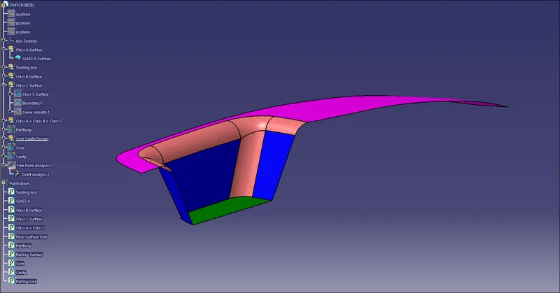
Click here to download the Class A surface.
Tooling Axis Creation:
For creating the tooling axis, we have extracted the base surface and created a point over the surface. As shown below:
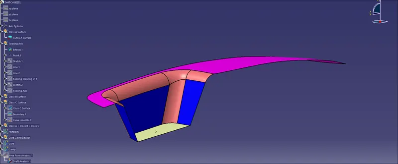
Now create an intersection of Class A with the YZ plane and create two lines as shown in the below figure.
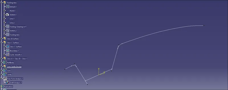
Now create a bisection line for these two lines as follows.
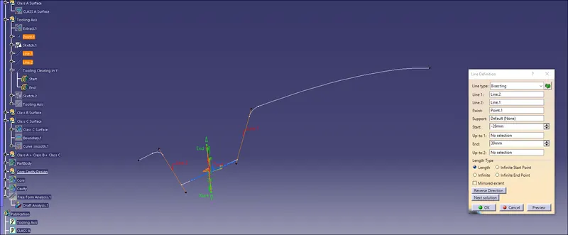
In other sketch create an intersection of the class A with the ZX plane and create an axis with the help of that sketch at an minimum angle of 3deg.
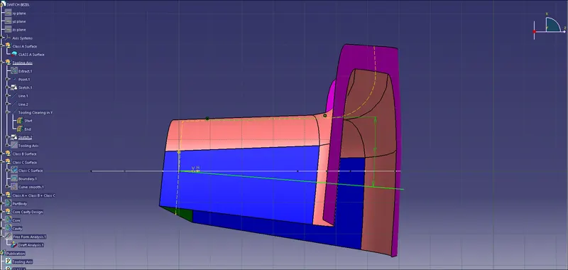
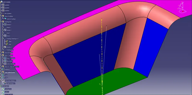
Now, use these two axis obtained to create a bisection, this will be the Main Tooling Axis.
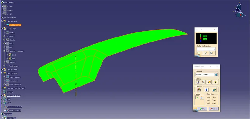
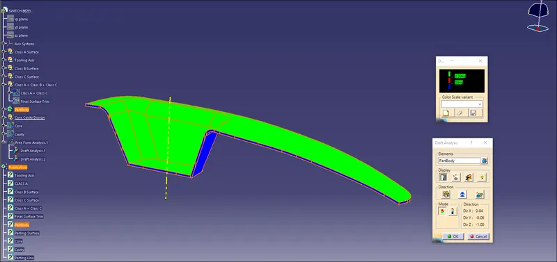
Draft Analysis on Class A:
Creation of Class B:
To create Class B surface, we have used the method of extraction of class A surface. These surfaces are then trimmed and then extrapolated.
These surfaces are then offset at the required thickness and then trimmed together for the required shape.
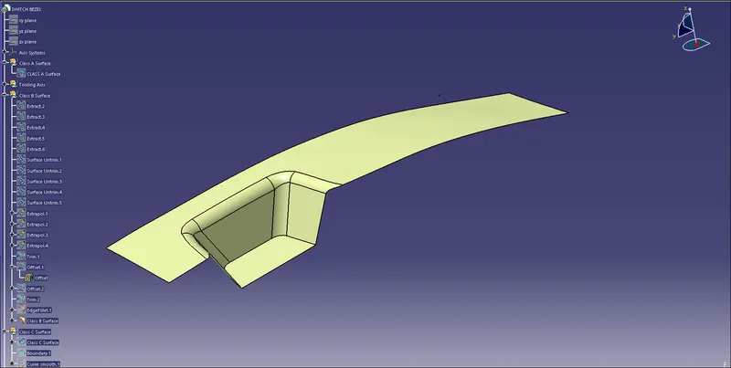
All the required steps are shown in the tree structure shown along side.
Class C Creation:
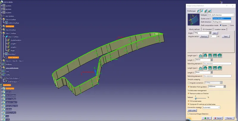
For creating this surface, Class A surface boundry is extracted and then converted into smooth curve. This is then swept along the tooling axis with a draft of 3deg.
Final Surface:
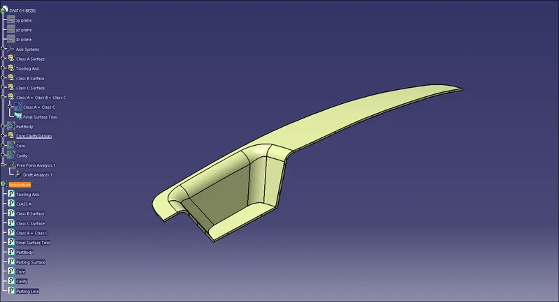
The surfaces are then joined and trimmed together to form the final enclosed surface of the component.
The Class A and Class C are joined together to form a single surface and then trimmed with the Class B trimming the unwanted portion.
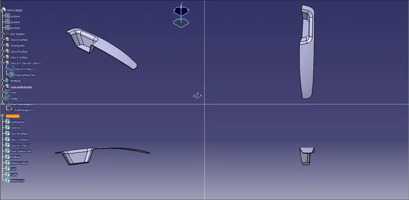
Final Plastic Component and Different Views:
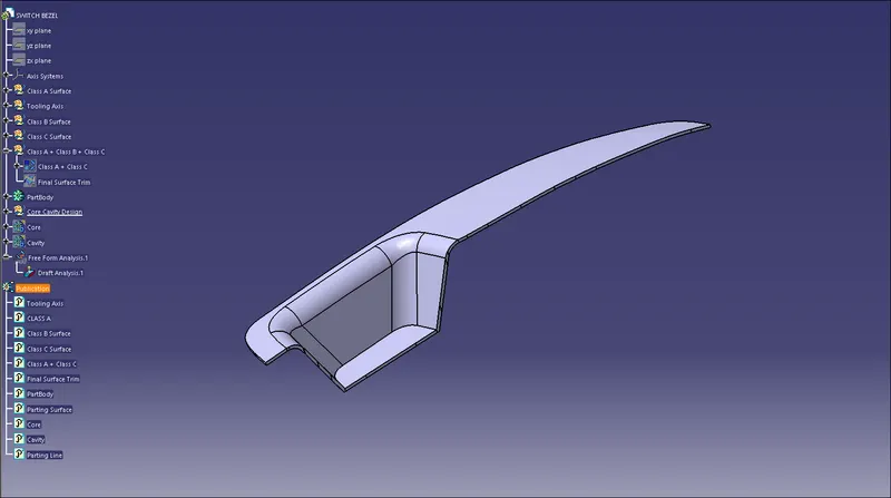
To create the final plastic component we have to use the above final closed surface and use the closed surface tool of the part design workbench.
Draft Analysis on the Component:
Creation of Parting Surface:
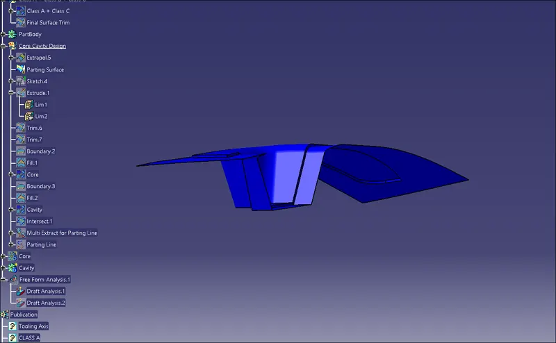
To create the parting surface, the Class A and Class C surface joined and trimmed with the Class B Surface to obtain the below surface.
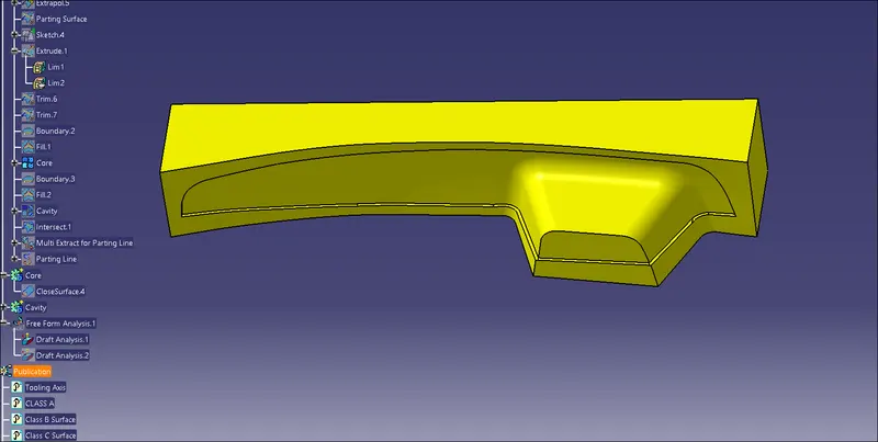
Core and Cavity Design:
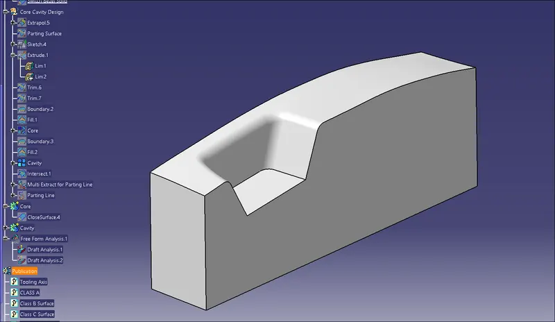
Core-Cavity, Parting Surface and Parting Line: